Difference between revisions of "42Q-MES0142 Tooling Control"
| Line 1,180: | Line 1,180: | ||
| − | = <span class="mw-headline" id="Appendix"><span class="mw-headline" id="Appendix"><span class="mw-headline" id="Appendix"><span class="mw-headline" id="Appendix"><span class="mw-headline" id="Appendix"><span class="mw-headline" id="Appendix"><span class="mw-headline" id="Appendix"><span class="mw-headline" id="Appendix"><span class="mw-headline" id="Appendix">Appendix</span></span></span></span></span></span></span></span></span> = | + | |
| + | = <span class="mw-headline" id="Appendix"><span class="mw-headline" id="Appendix"><span class="mw-headline" id="Appendix"><span class="mw-headline" id="Appendix"><span class="mw-headline" id="Appendix"><span class="mw-headline" id="Appendix"><span class="mw-headline" id="Appendix"><span class="mw-headline" id="Appendix"><span class="mw-headline" id="Appendix"><span class="mw-headline" id="Appendix">Appendix</span></span></span></span></span></span></span></span></span></span> = | ||
| | ||
| Line 1,222: | Line 1,223: | ||
*Configure the Tooling mapping information in the '''Tooling Mapping '''module (set the'''Control Mode = By Location, Tooling Pool = NO; '''Configure the number of the tooling that is'''QTY/Max QTY).''' | *Configure the Tooling mapping information in the '''Tooling Mapping '''module (set the'''Control Mode = By Location, Tooling Pool = NO; '''Configure the number of the tooling that is'''QTY/Max QTY).''' | ||
| − | |||
| − | |||
| − | |||
*The users select the Asset ID at the'''Tooling Load/Unload page. ''' The loaded QTY must be equal to the QTY/Max QTY'''.''' (If the '''Loaded QTY = QTY/Max QTY, '''the production unit scanning is allowed). | *The users select the Asset ID at the'''Tooling Load/Unload page. ''' The loaded QTY must be equal to the QTY/Max QTY'''.''' (If the '''Loaded QTY = QTY/Max QTY, '''the production unit scanning is allowed). | ||
| Line 1,262: | Line 1,260: | ||
'''Workflow A4''' | '''Workflow A4''' | ||
| − | # | + | #Configure the Maintenance strategy in the CMMS Asset module. (Tick the Periodic Control in the Maintenance tab page for Asset or Asset Type). |
| − | + | #Configure the Tooling mapping information in the Tooling Mapping module (set the Control Mode = By Location; configure the number of the tooling that is QTY/Max QTY). | |
| − | Configure the Maintenance strategy in the CMMS Asset module. (Tick the Periodic Control in the Maintenance tab page for Asset or Asset Type). | ||
| − | |||
| − | # | ||
| − | |||
| − | Configure the Tooling mapping information in the Tooling Mapping module (set the Control Mode = By Location; configure the number of the tooling that is QTY/Max QTY). | ||
| − | |||
#Load the Asset ID to the location in the exact quantity configured at tooling mapping QTY/MAX QTY. As production goes on, the system will create a maintenance work order and send an alert email to associated groups when the current date reaches Grace Period before the last maintenance date. As long as the user completes the work order before the date milestone, production will continue. Otherwise, the system will send a hold to stop production. | #Load the Asset ID to the location in the exact quantity configured at tooling mapping QTY/MAX QTY. As production goes on, the system will create a maintenance work order and send an alert email to associated groups when the current date reaches Grace Period before the last maintenance date. As long as the user completes the work order before the date milestone, production will continue. Otherwise, the system will send a hold to stop production. | ||
| Line 1,306: | Line 1,298: | ||
'''Workflow B2''' | '''Workflow B2''' | ||
| − | The workflow B2 is the same as workflow A2, except for the following configuration: | + | The workflow B2 is the same as workflow A2, except for the following configuration:Configure the Tooling mapping information in the''' ''''''Tooling Mapping''' module (cet the '''Control Mode = By Part Number, Tooling Pool = No;''' configure the number of the tooling that is '''QTY/Max QTY'''). |
|- | |- | ||
| Line 1,332: | Line 1,324: | ||
'''Workflow B4''' | '''Workflow B4''' | ||
| − | The workflow B4 is the same as workflow A4, except for the following configuration:'''Configure the Tooling mapping information in the'''Tooling Mapping''' module (set the'''Control Mode = By Part Number; '''configure the number of the tooling that is'''QTY/Max QTY'''). | + | The workflow B4 is the same as workflow A4, except for the following configuration:'''Configure the Tooling mapping information in the'''Tooling Mapping'''module (set the'''Control Mode = By Part Number; '''configure the number of the tooling that is'''QTY/Max QTY''').''' |
|- | |- | ||
| − | | style="width: 130px;" | | + | | style="width: 130px;" | By Shop Order |
| style="width: 153px;" | | | style="width: 153px;" | | ||
| | ||
| − | + | Usage Control | |
| | ||
| − | | style="width: 135px;" | | + | | style="width: 135px;" | C1 (Using Tooling Control) |
| style="width: 508px;" | | | style="width: 508px;" | | ||
| − | + | '''Workflow C1''' | |
| + | |||
| + | The workflow C1 is the same as workflow B1, except for the following configuration: | ||
| + | |||
| + | * | ||
| + | Configure the Tooling mapping information in the''''''Tooling Mapping''' module (set the '''Control Mode = By Shop Order; '''configure the number of the tooling that is'''QTY/Max QTY).''' | ||
| + | |||
|- | |- | ||
Revision as of 00:52, 9 February 2024
42Q Home > Shop Floor Control > Configuration > 42Q Tooling Control
Contents
- 1 Introduction
- 2 Tooling Modules
- 3 Workflow
- 4 Configuration Requirements
- 5 Tooling Mapping
- 6 Bulk Tooling Mapping
- 7 Tooling Load/Unload
- 8 Manual Update Usage
- 9 Production Workbench
- 10 Tooling Where Used
- 11 Tooling Reports
- 12 Other Resources
- 13 Appendix
Introduction
42Q tooling control integrates with MES 101, CMMS, and MESWeb, to provide ultimate control and traceability for factories that utilize tooling equipment (e.g. test jigs, test fixtures, solder paste stencils and squeegees, vacuum blocks) in conjunction with their assets.
Tooling Modules
Tooling is completed within several 42Q modules.
The Tooling Control module, housed inside CMMS, is used by engineers to define maintenance profiles, including the usage of count parameters to track for tooling.
- Tooling Mapping associates MES 101 data (production part numbers, process, location, shop order) with tooling equipment, in order for 42Q to count the usages by scan activity.
- Tooling Load/Unload captures tooling usage as production operators scan units at the mapped location.
- Tooling Reports: Plants can view a complete unit history of all tooling activity in the Tooling Reports feature, located within MESWeb.
- Manual Update Usage: Plants utilizing Tooling Control as a standalone feature without MES 101 can manually track tooling usage in the Manual Update Usage module.
The system also provides the other two methods to control toolings: by the tooling Expired Date, or by Periodic Control maintenance, which is based on a time range.
Three levels of control mode: by location, by part number, and by shop order are supported to define which tooling should be placed at which location on what kind of basis.
- The most generic level by Location, it can be used not only for toolings but also for some big machines, kind of assembly or simple setup oriented. No matter what products or shop order, as long as the boards are going to pass this location, the machine needs to be set up here and the usage needs to be tracked.
- For Location' combined with Part Number, 'somewhat in the middle level compared with by location, for example, assembly location, a lot of products will go through this location using the same tools and the usage needs to be tracked across the part number by location.
- For Location combined with Shop Order, the most specific level like SMT lines change-over centric, the users need to do the maintenance/basic cleaning once they change the shop order at the location.
Workflow
The system provides three types of tooling maintenance criteria: by tooling usage control, by tooling expired date, or by periodic control.
- Tooling configuration details are input in CMMS Assets.
- Conduit parameters are defined to utilize Production Scanning.
- Operator scans the tooling part number at the Load/Unload station.
- 42Q’s MES 101 event broker broadcasts the unit move transaction to CMMS.
- CMMS validates the tool to ensure:
- The selected tools' asset status
- The selected tools' usage/expired date/ periodic control configuration for the following:
If the tools’ usage control is configured, when it reaches the threshold before usage milestone, CMMS will create a work order, if the work order has not been conducted until the usage reaches a milestone, it will send an MFG on hold request to MES 101 to stop production, and the asset status will change to the next status. If the work order is conducted before the milestone reaches, the MFG hold won’t be triggered. After the work order is closed, the CMMS system will update the tooling to the next milestone and the production won’t be affected.
If the tools’ expired date control is configured, CMMS will create a work order and change the asset status to next status, and then will send an MFG on hold request to MES 101 to stop production.
If the tools’ periodic control is configured, when it reaches the Grace Period before the date milestone, CMMS will create a work order, if the work order has not been conducted until the date milestone, it will send an MFG on hold request to MES 101 to stop production, and the asset status will change to the next status.
- If an MFG Hold is generated, the engineer ,ust then resolve the issue by:
- Replace with a valid tool or unload the original tooling and then load a new one.
- Unload the tooling, complete the usage/periodic work order, and manually change the status on the current tool, and then load to the CMMS system again.
- Tooling usage details are now reflected in Tooling Usage Report and Tooling Where Used by Serial Number (CMMS Reports) at MESWeb.
- If no scanning interface system is employed but the user still wants to track the usage situation, or if the user wants to adjust the tooling usage after loading/unloading and tooling validation, it can be complete manually in Manual Update Usage.
There are three control Modes and three types of tooling/asset maintenance criteria that can be configured for asset type and asset. Please see the Appendix for detailed workflow if needed.
Configuration Requirements
Tooling Control operates within several modules, configuration requirements involve multiple steps.
If the users have configured all the data, please skip the configuration sections, go to the tooling map directly.
This document outlines the following configuration details:
The Tooling Mapping module allows the users to create an association between the product’s Location/Part Number/Shop Order (associated with the Shop Floor ID and configured in MES 101) and the Asset Type defined in CMMS Asset.
As shown in Figure 1, before making the tooling mapping, the requirements configurations must be ready.
Figure 1: Tooling Mapping Fields
Note: The Shop Floor ID, Part Number, Process, Location and Shop Order were configured in the MES 101.
Note: The Asset Type ,Usage Threshold UoM and Usage Rate were configured in the CMMS module.
MES 101 Configuration
Shop Floor ID, Location, Part Number Control
- Navigate to:Shop Floor Control > Configuration > Shop Floor Configuration.
- Utilize the Shop Floor Configuration submodules to configure production data:Shop Floor ID, Location, Part Number.
For more information about how to add configuration data, see this step-by-step document.
Shop Order Control: Create Shop Order
- Navigate to:Shop Floor Control > Production Control > Shop Order Control.
- Open the Shop Order Release module to set the Shop Order.
Server Information
Please configure the Shop Floor Id at the Server information, Or contact the Support Team to configure the server information.
CMMS ConfigurationServer Information
Configure UoM(unit of measurement)
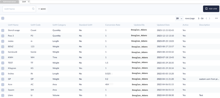
Usage Threshold UoM and usage rate were defined at the UoM module.
- Navigate to: Shop Floor Control > Configuration > CMMS-Admin to open the Asset main menu.
- Select UoM to manage the UoM.
- Define the UoM Category and Conversion Rate.
Figure 2: UoM Main Page
Configure Asset Type
Asset Type is a group of Assets with a unique ID but has some generic characteristics as an asset class; which allows users to configure asset maintenance and assign maintenance to a dedicated technician group according to machine type.
At the asset type Maintenance Tab, the users can select one, two, or three types of tooling maintenance options for each maintenance tool based on usage or time range.
- Usage Control
- Expired Date Control
- Periodic Control
Below will give a detailed description of Asset Type Maintenance.
- Go to:Shop Floor Control > Configuration > CMMS - Asset to open the Asset main menu.
- Select Asset Type to manage the Asset type.
- Select the Maintenance tab to configure the Asset Type’s Usage/Expired Date/Periodic Control information.
Asset Type Maintenance Tab
Three kinds of maintenance can be configured on the Asset Type.
- Usage Control
- Expired Date Control
- Periodic Control
Note: Plants can select one, two, or three types of maintenance for each maintenance tool. To edit the Asset Type, select the maintenance type by marking the checkbox next to the Maintenance Type Heading. The default value is unselected.
Note: This figure below ticks all three maintenance control types just to show the fields clearly.
Figure 3: Asset Type Maintenance Tab
- Assigned Group: Define the user group to complete the maintenance work order on this tool.
- Requester Group: Define the user group that has permission to request a maintenance work order for this tool, i.e. who can request the tooling maintenance requirement.
- Comment: Users can add any additional information in this field.
Usage Control
To define maintenance thresholds, users must complete the fields according to usage.
Figure 4: Usage Control
- Maximum Usage: This is the maximum usage value allowed for the Asset Type. If the tool’s current usage exceeds the maximum usage defined, the tool will change to Next Asset Status configured at Usage Control, and a Manufacturing hold will be placed for this tooling's location to stop production. Scanning at that location will be disabled until the required tooling is loaded (Users need to unload the invalid tooling, then load another valid tooling, or replace the tooling).
Important Note: If Max Usage is reached, the production line will stop. Please prepare a tooling replacement plan in advance.
- Usage Interval:
Note: There are two types of usage interval, Regular interval and Irregular interval.
- The Regular interval usage control configuration, please see Figure 5.
As an example shown at the Figure 4, Maximum Usage is 1000, Usage Interval is 100, which signifies that the tool requires maintenance after every 100 usages, and the CMMS system will auto-generate the usage milestones with the same interval. So the usage checkpoint will be 100,200,300,400,500,600,700,800,900 (supposing the Usage Warning is 5). When the tooling usage reaches 95,195,295,395,495,595,695,795,895,995 the system will create a maintenance work order. As long as the users conduct the Work Order before it reaches the milestone, scanning will continue without any disturbance.
- The Irregular Interval usage control configuration, please see Figure 6.
Figure 5: Usage Irregular Interval Control
- Irregular Usage Intervals are entered as a series with a comma between (e.g. 100,300,500,800,900), meaning the usage milestone changes between each maintenance. As an example shown at Figure 5, the Usage Interval for the Tool is defined as “100, 300, 500,800,900,” signifying the usage checkpoint is 100, then 300, 500,800, then 900 (supposing the Usage Warning is 5). When tooling usage reaches each milestone (95, 295, ,495,795,and 895), the system will create a maintenance work order. Note: Usage Intervals are listed in a row, with commas separating them.
- Usage Warning: Usage Warning number is set to define when to create a work order, once this number is reached before each usage milestone, a work order will be created with a checklist for each asset and notify the user.
- Example: Maximum Usage is 100000, and Usage Interval is 30000, so the usage milestones will be 30000,60000,90000,
Usage Warning is 10, so the system will create a maintenance work order and send an alert email to the associated group when the tooling’s current usage reaches 29990,59990 and 89990 (usage milestones - Usage Warning).
Note: If the users do not conduct the maintenance work order when the current usage reaches each usage milestone (30000,60000,90000), the system will send a hold command/information to the MFG production line, and the production will be halted/stopped. Once MFG Hold is placed, users need to unload the tooling, close the WO (asset status will be changed automatically), and then load the tooling again. You can check the auto status change at History Tracking for Asset Status.
Note: The Usage used in this document will only help to understand the operating process, in the real shop floor, the usage checkpoint maybe 30000,60000,90000 or any number the engineer thinks appropriate for the tooling used for products. Please set the usage data according to your business scenarios.
- Unit of Measure: Define the Unit of measurement for this Asset type. The UoM(unit of measurement) is defined atCMMS-Admin >UoM.
- Usage Checklist: Define the checklist to assist the technician in the tooling maintenance. The checklist is defined at CMMS-Asset > Checklist.
- New Asset Status: Defines the Status of the Asset/Tooling. The options display are:
- Running: Tool is currently running on the line.
- Obsolete: An asset that has been temporarily or permanently moved from production.
- Spare: Tooling is not currently in production but is available for use if needed.
- In Maintenance: The tool is currently being maintained by PM plan.
- Unscheduled Down: Tooling breaks down unscheduled.
- Scheduled Down: Tooling is down scheduled.
- Setup: Tooling is currently waiting for running because of setup.
- Idle: Tooling is not in use.
- Calibration: The tooling is under calibration process.
- To be reviewed: This status happens when the tooling maintenance work order is not conducted till milestone reaches or maximum usage has reached but the engineer wants to double check before scrapping..
- Suggested value = To be reviewed if you want to check the real status before scrapping the tool .
Note: When usage milestone is exceeded or grace period expires, the system changes asset status to Next Asset status (for example. “to be reviewed”). After maintenance is completed and tooling is correctly loaded, the system will then change the asset status to Running. Technicians have the option to manually change the status if necessary (e.g. If maintenance is not needed, the technician can manually close the work order and change the status of the asset to Running; if extra maintenance is necessary the technician may also manually change Running status to Obsolete or other status, etc.)
Expired Date Control
To define maintenance thresholds, users must complete the fields according to the time periods.
Figure 6: Expired Date Control
- Expired Period (Months): The number of months from the manufacture date when the asset will expire and require maintenance. The following example illustrates an expired period of 12 (months). If the Manufacture Date is 2019-01-30, (Note: Manufacture Date is defined when the user defines the Asset: CMMS Asset > Asset > Add), this Asset will expire on 2020-01-30, 12 months after 2019-01-30.
- Expired Checklist: Attach the maintenance checklist the technician should follow to complete maintenance on this tool (asset).
- New Asset Status: Define the Status of the Asset/Tooling. For Asset Type assets, the default selection is “Obsolete” or “To be Reviewed”. If usage moves beyond the acceptable limits, the system automatically changes Asset Status “To be Reviewed.” Once maintenance is completed, the engineer needs to change the status to “Running.” or any other status they deem proper after checking the tooling status. If the engineer reviews the tooling and deems it does not require scrap, he can manually change the status to Running, Obsolete, Spare, In Maintenance, or Break Down, as needed.
- Default status is “To Be Reviewed”. Please see theNew Asset Status.
Note:The system will create a maintenance work order and send an alert email to associated groups when the asset expires. CMMS will send a hold command/information to the MFG production line, and production will be halted/stopped. Replace the valid tool or unload the original tooling, and then load a new one.
Periodic Control
Users must complete the fields to define maintenance thresholds according to calendar dates.
Note: This configuration mirrors configuration options for CMMS assets.
Figure 7: Period Control
- Repeat Every: Define the number of Repeat cycles.
- Repeat Type: The choice values are Day, Month, Year.
- Grace Period: This is the number of the Grace Period. For example, select Repeat type today, last maintenance date is 10/15/19, Repeat Every is 10, Grace Period is 1, when reaching 10/24/19 system will create maintenance work order automatically.
- Grace Type: The choice values are Day, Month, Year.
- Periodic Checklist: Attach the checklist for the technician to mark when completing the maintenance.
- Grace Orientation: Define the orientation for grace, choice values are Backward/Forward, Backward.
- New Asset Status: Define the Status of the Asset/Tooling when a repair is complete. This field is completed by the technician assigned. Please see theNew Asset Status.
Note: The system will create a maintenance work order and send an alert email to associated groups when the current date reaches the lastmaintenance date + Repeat Type(Day/ month/year) - Grace period. Follow the checklist to complete the maintenance and change the status of the asset manually. If the users do not conduct the maintenance work order between the Date Last maintenance Date + Repeat Type(Day/ month/year) - Grace period and Last maintenance Date + Repeat Type(Day/ month/year) + Grace period, the system will send a hold command/information to the MFG production line, and production will be halted/stopped. The users need to change the asset status to continue scanning if needed.
- The user must complete the fields according to the required information.
- Add the fields accordingly, then select Save to save the configuration.
Asset Maintenance
Once the Asset Type (Tooling Part Number) has been defined, users must configure the Asset (Asset ID) in CMMS Asset.
- Navigate to: Shop Floor Control > Configuration > CMMS Asset > Asset.
- SelectAdd at the Asset list main page, the Add Asset sub-page will show.
- Enter or select theAsset ID, Asset Name, Asset Type, and other items, then select Save.
- Select the Asset, then select theEdit to open the newly created Asset.
- Move to theMaintenance Tab.
Note: All data previously defined in Asset Type is inherited by the Asset, unless the Maintenance Needed and Inherited from Asset Type checklist is deactivated.
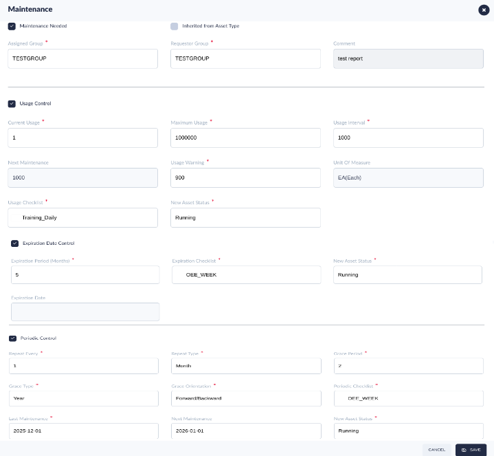
Figure 8: Edit Asset - Maintenance Tab
- Complete the columns according to the Asset ID:
- Maintenance Needed: The Maintenance Needed checkbox determines whether the tool’s maintenance will be monitored by the system. If left unchecked, no maintenance (by usage, by expired date, and by periodic) for this tool will be monitored.
- Inherited from Asset Type: When checked, all usage parameters defined in the corresponded Asset Type will automatically be populated for this asset. Users can uncheck the Inherited from Asset Type checkbox, then manually set the special configuration for the Asset.
Tooling Mapping
The Tooling Mapping module creates an association between the product’s Location/Part Number/Shop Order (associated with the Shop Floor ID and configured in MES 101) and the Asset Type defined in CMMS Asset. This connection allows the system to identify tooling maintenance type (tooling usage/tooling expired date/tooling periodic maintenance) via scan activity. Tooling Mapping sends tooling requirements to Conduit, 42Q’s Production Workbench portal.
Tooling mapping provides three control modes to control the Tooling Maintenance: By Location, By Part Number, By Shop Order.
- By Location means specific asset type is controlled by location directly, this can be used for big machine’s setup too, After establishing the relationship between tooling and the Location, the system will check the loaded toolings status and the toolings maintenance work orders status for the Location, and will hold any part number or shop orders when it goes through this location if the users do not conduct the maintenance work order on schedule.
- By Part Number means specific asset type is controlled by Part Number. After creating the relationship between tooling and the part number, the system will check the loaded toolings status and the toolings maintenance work orders status for this part number, and will hold all the units or shop orders for this part number if the users do not conduct the maintenance work order on schedule.
- By Shop Order means specific asset type is controlled by shop order directly. After establishing the relationship between tooling and the shop order, the system will check the loaded toolings status and the toolings maintenance work orders status for the shop order, and will hold this shop order if the users do not conduct the maintenance work order on schedule.
The Tooling Mapping module is necessary to create an association between the product's Part Number (associated with the Shop Floor ID and configured in MES 101) and the Asset Type defined in CMMS Asset. This connection allows the system to identify tooling usage counts via scan activity on the Product's Part Number. Tooling Mapping connects tooling requirements to conduit, 42Q's Production Scanning portal.
Tooling Pool
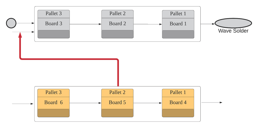
Tooling mapping also provides options for using the Tooling Pool, depending on the asset type and business scenarios. The tooling pool means that more than one tooling can be set in a certain station as if all the tooling are put in a pool to use. It can be used in some stations/locations that take a long time and the users cannot wait for the tooling to be back to scan the next board, such as pallets and vacuum blocks at the wave solder process. To improve production efficiency it is necessary to prepare a lot of tools in advance, such as pallets, instead of waiting for the pallets in front. Based on this, it is required that only the picked tooling (pallet/trays) will be increased by usage, rather than increasing usage to all the toolings in the pool.
If the tooling pool is configured as'NO, the logic is that, when one board is completed or passed, the usages of all toolings on the current station/process/location will be increased.
In consideration of the business scenarios in the shop floor, the Tooling Mapping page provides theTooling Pool options for flexibility to allow users to define whether the asset type used, should be in the tooling pool or not.
Tooling Pool: YES/NO
Tooling Pool is YES:
- The Qty of the tooling is higher than one at the tooling mapping, and each loaded tooling with a Loading Sequence, as well as the usage of the currently used tooling, will increase when the board passed from the location, while the usage of other toolings in this pool will not increase. The total amount of the toolings in the tooling pool depends on how many tooling the users have loaded for this location.
- The increase in the tooling pool can be interpreted in a cycled counting concept. For example: there are 3 toolings in this tooling pool, the sequence is automatically defined by the system, according to the order of toolings loaded time: the first tool loaded, then the Loading Sequence will be set to 1, after 3 toolings had been loaded, it means that the total toolings in the pool is 3. When the first board is completed/passed to the next location, the first tooling (loading sequence is 1) is used, and the usage will increase, when the second board is scanned, the usage of the second sequence tooling will increase, and so on. But when the fourth board is scanned, the usage of the first sequence tooling will increase.
Figure 9: An Example of the Tooling Pool
Tooling Pool is NO:
- Regarding the configuration (by location, part number or by shop order) in the tooling mapping, when a board passes, all the loaded tooling’s usage will increase.
Tooling mapping
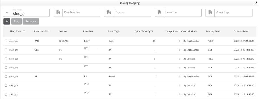
- Navigate to: Shop Floor Control > Configuration > Tooling Map, and open the Tooling Map main page.
Figure 10 : Tooling Mapping Main page
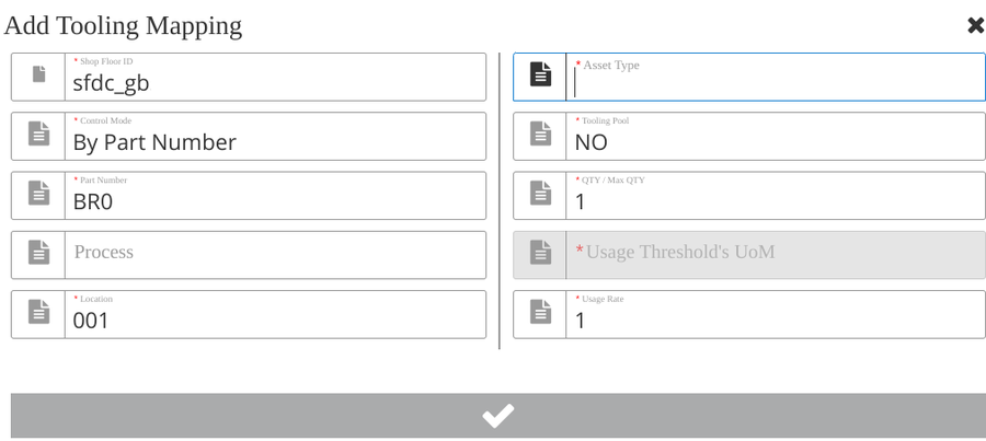
- Select the Add (+) button. The Add Tooling Mapping page will display.
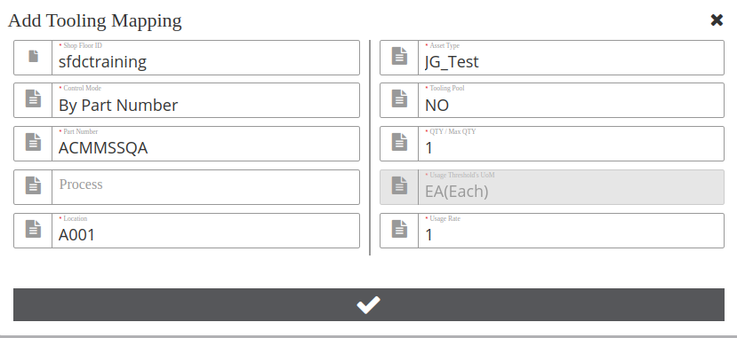
Figure 12 : Add Tooling Mapping subpage
- Input or select the following fields.
Note: Items noted with a red asterik (*) are mandatory fields.
- *Shop Floor ID: SFDC Shop Floor for the specific plant. This field cannot be empty. (To configure go to: Shop Floor Control > Configuration > Shop Floor Configuration > Shop Floor ID).
- *Control Mode: Select By Location, By Part Number, or By Shop Order.
-
- Control mode asLocation, means once mapped, the system will hold all the shop orders under this location directly.
- Control mode asPart Number, means once mapped, the system will hold all the shop orders under this Part Number directly.
-
- Control mode asShop Order, when scanning, CMMS will check the first board under this Shop Order for load and proceed accordingly.
- *Part Number: The MES product Part Number of MES 101 (SFDC). This field cannot be empty. By linking the product PN to the Asset type, the plant can quickly identify the correct Asset/tool needed to build the product. (To configure it, go to: Shop Floor Control > Configuration > Shop Floor Configuration > Part Number).
- Process: Process describes the scanning activity and/or assembly completed at a specific location. The process is defined at Shop Floor Control > Configuration > Shop Floor Configuration > Location).
- *Location: The process is defined at the module Location (Go to: Shop Floor Control > Configuration > Shop Floor Configuration> Location).
- *Asset Type This field corresponds to Asset Type and is defined in CMMS Asset (Shop Floor Control > Configuration > CMMS Asset > Asset Type > Maintenance Tab).
- *Tooling Pool: The option is used to define whether to use the tooling pool.
Yes: tooling pool is applicable here for the asset type.
No: tooling pool is not involved for the asset type.
- *Qty/Max QTY: The quantity of toolings (jigs/stencils etc) for the Asset Type that will be loaded for this Location.
Note: QTY Example:
- If the Tooling Pool is set to YES, the value of QTY/Max QTY must be more than 1, otherwise no pool if it’s only 1.
- If this Qty/Max QTY is set to 2 and the Tooling Pool is set to No, the users must load 2 toolings at this location; if the correct number of toolings are not all loaded, the line will remain in MFG Hold status to prevent scanning.
- If this Qty/Max QTY is set to 3 and the Tooling Pool is set to Yes, the numbers of the loaded toolings can be more or equal 1, and less or equal 3. That means the users can load 1, 2, or 3 toolings at this location to scan the board.
- The users can configure the option Tooling Pool to define whether the location/product supports tooling pool for one asset type at the Tooling Mapping page.
- If Tooling Pool = NO, after the user establishes a mapping relationship with Asset type and QTY is defined, users will need to load Qty/Max QTY toolings to be able to scan the boards, as CMMS requires the Loaded QTY (tooling load page) must be the same as Qty/Max QTY (tooling mapping page).
- If Tooling Pool = YES, it’s just like there’s a magazine or rack, put at the location with a lot of toolings with the same asset type (usually for pallets, vacuum blocks, carriers) at the shop floor, CMMS system builds up a virtual pool when loading the toolings to the location ready for use. The Qty/Max QTY at Tooling Mapping will be taken as the maximum number of tooling you will load for this location. The users who put even one tooling will be able to scan the board although it lacks efficiency because they need to wait for the tooling back to carry the second board.
-
- The maximum Loaded QTY for one asset type will be the Qty/Max Qty defined at Tooling Mapping. Loaded QTY must be less than or equal to the Qty/Max QTY defined in tooling mapping for location.
-
- CMMS will check Loaded QTY greater than 0 to allow scanning. Once 1<=Load QTY<= QTY/Max QTY, CMMS will send the “release MFG hold” event to MES101 to allow scanning.
-
- CMMS will calculate each tooling’s usage according to the Loading Sequence at the tooling pool after one board passes through the location.
-
- Once the maintenance criteria reach to trigger maintenance for one tooling, the users need to take out the specific tooling from the pool (unload the Asset ID at Tooling Load/Unload Page) and the Loading Sequence will update automatically for the remaining tools in the pool according to Load Time. Please refer to the Tooling load section in Figure 20.
- *Usage Threshold’s UoM: This is the UoM(units of measurement) for the Usage Threshold, which was defined at the CMMS -Admin >UoM and CMMS-Asset > Asset Type > Maintenance tab.
- *Usage Rage: This is the usage rate/ Conversion Rate of UoM(units of measurement) for the Usage Threshold, which was defined at theCMMS -Admin >UoM and CMMS-Asset > Asset Type > Maintenance tab. Usage Rate stands for how much of the tooling( in UoM) is to be used per scanning unit.
Note: The Usage Rate is useful in factories that scan the entire board, thereby eliminating extra usages being falsely recorded.
- Input or select the fields, then use the checkmark to save the new tooling mapping.
- Users can select Edit or Remove to manage the tooling mapping.
Bulk Tooling Mapping
The Bulk Tooling Mapping module is used to import the tooling mapping list information. The operator downloads the Template (in CSV format) file, edits the tooling mapping data, then imports the CSV file into the CMMS system.
- Navigate to:Shop Floor Control > Configuration > Bulk Tooling Mapping.
Figure 12: Bulk Tooling Mapping Main Page
There are 6 functions:
- Upload: To open the prepared tooling mapping file.
- Validate: To verify the data of the tooling mapping file are valid or not.
- Import: To import/save the valid tooling mapping into the CMMS system.
- Delete: To delete the invalid lines of the tooling mapping file.
- Export: To export the correction data of the tooling mapping to local.
- Template: To download the template file.
- Select theTemplate button, to download the template to the user’s desktop. Rename the CSV file and add the tooling mapping data:
- Shop Floor ID: Conduit/SFDC Shop Floor ID.
- Part Number: Part Number.
- Process: Process Name.
- Location: Location Name.
- Asset Type: CMMS Asset Type.
- Tooling Pooling: 0 does not loop count, 1 does loop count.
- QTY: Asset number needed under this Asset Type.
- Usage Rate: Usage Rate stands for how much of the tooling( in UoM) is to be used per scanning unit.
- Control Mode: ‘1’ stands for “By Shop Order”, ‘2’ stands for “By Part Number”, ‘3’ stands for “By Location”.
- Select theUpload button, to open the prepared bulk tooling mapping CSV file.
- The tooling mapping data will be listed below.
Figure 13: The Bulk Tooling Mapping Template
- Select the Validate button to verify the tooling mapping data
- All invalid data will show in red font.
Figure 14: Validate Tooling Mapping
- Select on the invalid data and correct it. Users can edit the tooling mapping information on the list, but this edit action does not sync to the initial CSV file or, select the invalid line and select Delete to delete the invalid data. Note: Users can delete any selected line by clicking the Delete button.
Figure 15: Delete Tooling Mapping
- The Import button will be enabled once all the tooling mapping data are validated.
- Select the Export button to export the current tooling mapping data to your local machine.
Figure 16: Export the Bulk Tooling Mapping
Note: If there’s already a tooling mapping record for the same Shop Floor ID + Part Number + Location + Asset Type (criteria as one unique record), then the system will update the existing tooling mapping record.
- Select the Import button to save the tooling mapping into the CMMS system. The system will send a successful pop-up message.
Note: If there’s already a tooling mapping record for the same Shop Floor ID + Part Number + Location + Asset Type (criteria as one unique record), then the system will update the existing tooling mapping record.
Tooling Load/Unload
The Tooling Load/Unload module is used by the production operator. The production operator needs to load the tooling for the SMT machine before they start the production line. The plant must make sure all the necessary/correct tooling is loaded at the SMT machine, so the quality of the product is not compromised. The system validates that the proper tool is loaded and is maintenance is up to date.
Navigate to: Production > CMMS > Tooling Load/Unload to open the tooling load/unload main page.
Tooling Load
- Select/Input Shop Floor ID.
- Input/Select Location.
- Select the Control Mode. There are three options:By Part Number (default), By Shop Order andBy Location.
- Input the Part Number, Shop Order Number orLocation.
- InputAsset ID.
- SelectLoad to load the tooling.
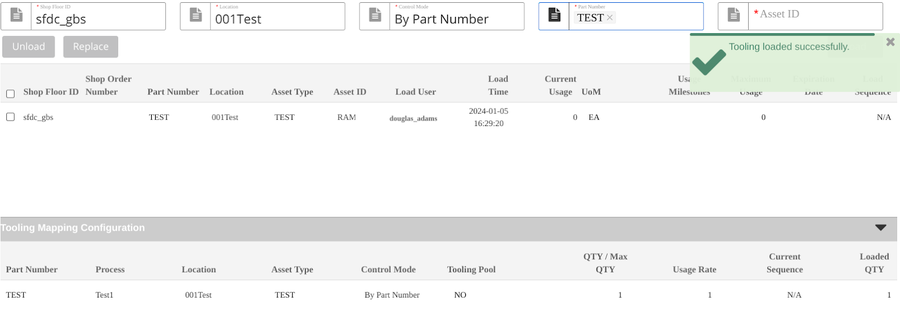
Figure 17: Load Tooling Succeed
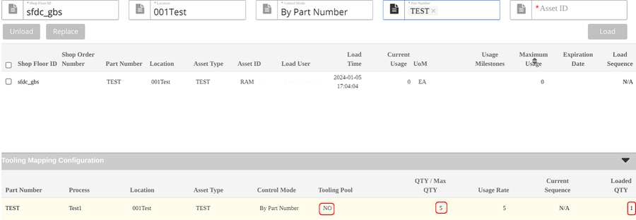
Note: Once users input the three items Shop Floor ID, Shop Order Number/Part Number, and Location, the loaded tooling information associated with the tooling mapping configuration detailed information will display at the list Tooling Mapping Configuration.
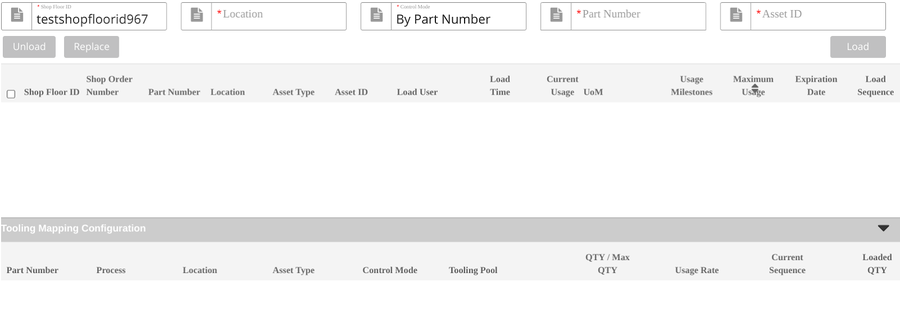
Figure 18: Tooling Load/Unload Main Page
Note: If the Tooling Pool is No and the loaded tooling Qty is less than the QTY/Max QTY configured at the tooling mapping, this line will be in yellow color, the users must load all the defined Max QTY tooling to release MFG hold to the scan board. Note: If the Tooling Pool is Yes and the loaded tooling Qty is less than the QTY/Max QTY configured at the tooling mapping, this line will not be in yellow. It allows the users to use the tooling pool. User loads at least one tooling (equal or less than the QTY/Max QTY) to release the MFG hold to the scan board. After the tools are loaded, the system will auto-generate/increase the sequence of the tools.
Figure 19: An Example for loading Mapping Configuration
If the loaded tooling number is less than the configured tooling mapping number, this line will be in yellow color.
Tooling Unload
Select the loaded tooling, then click Unload to unload the tooling from the location.
Figure 20: Unload Tooling
Note: If the Tooling Pool = Yes, the system will auto minus 1 of the sequence of subsequent tools after unloading the tool. If the current sequence in tooling mapping is the same as the sequence of the tool unloading, and the tooling is the last one, the current sequence will change to 1. If Tooling Pool = No, Loading sequence will be N/A.
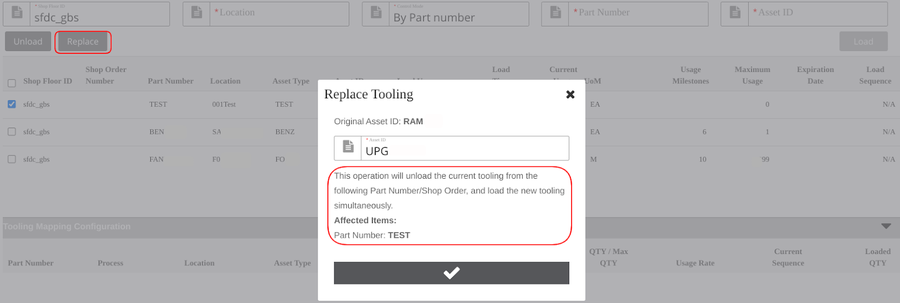
Tooling Replace
Note: The users must unload the old toolings then load the new toolings, when they need to switch new toolings. Tooling Replace function is one way that allows users to switch to new tooling quickly.
Select the tooling record that needs to be replaced from the list.
Select the Replace; replace tooling will pop up.
Enter the new Asset ID.
Select Checkmark to replace the tooling.
Figure 21: Replace Tooling
Note: The replace operation will unload the current tooling from the associated Part Number/Shop Order, and load the new tooling simultaneously. The sequence of new tools is the same as the old one if the tooling pool control is used.
Manual Update Usage
The Manual Update page is used in the following manufacturing scenarios:
- Scenario 1: Plants with no Shop Floor ID configured to their location (plants operating CMMS Asset as a standalone feature) use Manual Update Usage to manually add tooling usage times, thereby providing a complete log of all tooling usage.
- Scenario 2: Plants can maually adjust incorrect usage times recorded by MES101 (unit move by usage) in the Manual Update Usage module.
Navigate to: Production > CMMS > Manual Update Usage. Input the following fields prior to loading the tooling:
Shop Floor ID (Optional).
Shop Order Number (Optional): This is the identifier for the production PN.
Location (Optional): The production line’s location according to the process.
*Asset ID : (Mandatory) The Tooling’s unique ID, configured in CMMS Asset.
*Usage: (Mandatory) The number of times this tooling has been used already.
Figure 22: Manual Update Usage Screen
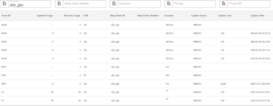
Previous Usage easily shows the user the original usages before manual update. Updated Usage changed to Manual Updated Usage to show the updated times, this will also distinguish the current usages field at Tooling Load to avoid confusion.
Users input Shop Floor ID, Asset ID, and select Enter; all the usage update history will display in the list.
Figure 23: Manual Update Usage History
Production Workbench
Tooling Control cannot be used as a standalone system without MES 101 for scanning activities, currently it utilizes the Production Workbench or other scanning interfaces like Data Collector Scan activities. After toolings are configured or loaded, when scanning the board at Production Workbench etc, it will check tooling status for this location.
Prerequisites for Production Workbench
- Additional server installation is required to use the Production Workbench:
- Conduit Server: The conduit URL server submits data captured in Production Workbench to the API.
- Shop Floor ID: Define the factory’s Shop Floor ID server to begin scanning activity.
- Conduit-ccrs: The interface URL server enables Production Workbench to read the Conduit command list.
- Conduit-MES-API: Server that reads data from SFDC.
- Production Workbench is located in:Production > Production Workbench.
For further information, please seeProduction Workbench SOP.
Tooling Where Used
TheTooling Where Used module provides a complete log of all tooling records. Tooling Where Used is a view-only submodule located in CMMS Reports. To access Tooling Where Used, navigate to:Reporting > MESWeb > CMMS Report > Tooling Where Used by Serial Number
Note: For more information, please refer to Tooling Where Used.
Figure 24: Tooling Where Used Submodule
Figure 25: Tooling Where Used View Only Page
For more details about search parameters see: CMMS Reports > Tooling Where Used.
Search the information using the filter criteria.
Export the report if needed.
Tooling Reports
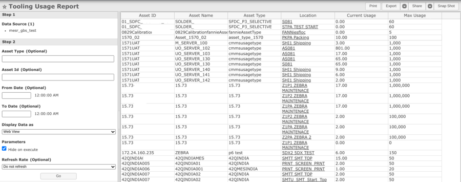
Tooling Usage Report
Tooling unit history is available in MesWeb Reports according to the shop floor Serial Number (SN) assigned to the tooling (Tooling Mapping).
Tooling usage report is available in MESWeb reports
- Navigate to: Reporting > MESWeb>CMMS Reports > Tooling Usage Report
- Select the Data Source (Step 1)
- Input the optional field in the search field if needed, then select Next.
- The users can view the tooling where used by the serial number report when clicking the link at the Location field
Figure 26: Tooling Details for Production SN
Tooling Where Used by Serial Number
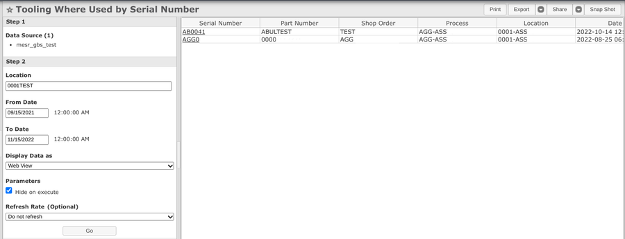
Tooling Where Used by Serial Number report is available in MESWeb reports.
- Navigate to:Reporting > MESWeb
- Select CMMS Reports > Tooling Where Used by Serial Number
- Select the Data Source (Step1)
- Input the optional field in the search field if needed, then selectGo.
- The users can view the Unit History report when clicking the link in the Serial Number field.
Figure 27: Tooling Where Used by Serial Number
MESWeb Unit History Report
Tooling unit history is available in MesWeb Reports according to the shop floor Serial Number (SN) assigned to the tooling (Tooling Mapping).
- Navigate to:Reporting > MESWeb
- Enter the Unit History report name to find the report quickly
- SelectUnit History report
- Enter theSerials in the search field
Figure 28: Tooling Details for Production SN
Note: Serial Numbers associated with an asset or tooling are labeled with a wrench icon.
Select the wrench icon to expand the line entry and view more details about the tooling activity.
Other Resources
The users can view the CMMS hold and the maintenance work order list.
CMMS Hold Type List
In situations where toolings exceed usage and/or expired maintenance defined but are still acceptable for use, a manager may waive the MFG hold and continue production with the current tooling. In such cases, the manager must also add a comment (description). All comments and timestamps for CMMS MFG hold waivers are recorded in the Manufacturing Hold module of MES101.
Navigate to:Shop Floor Control > Configuration > Shop Floor Configuration > MFG Hold
Enter the PN, Shop Order or Serial Number
Select CMMS Hold Type
Select Filter
Figure 29: CMMS Hold Repot
Note: For reference see more details about manufacturing holds:MFG Hold Maintenance
Maintenance History Report
A complete history of all tooling maintenance is available in CMMS Work Order.
- Navigate to:Production > CMMS > Work Order.
- Select on theWork Order icon.
- Select filter by Maintenance from the W/O Type drop-down menu.
- Expand the list item to view maintenance work order details.
Appendix
There are three control Modes and three types of tooling/asset maintenance criteria that can be configured for asset type and asset. Please see the detailed workflow if needed.
Control Mode |
Asset Mantain Control Data Type | Workflow Name | Workflow description |
|
By Location |
Usage Control |
A1 (Using Tooling Pool) |
Workflow A1
|
| By Location | Usage Control | A2 (Do not using Tooling pool) |
Workflow A2 The same as Workflow A1 except the two configurations following:
|
|
By Location
|
Expired Date Control | A3 |
Workflow A3
|
| By Location |
Periodic Control
|
A4 |
Workflow A4
|
|
By Part Number |
Usage Control
|
B1 (Using Tooling Pool) |
Workflow B1 The workflow B1 is the same as workflow A1, except for the following configuration:
|
|
By Part Number |
Usage Control
|
B2(Do not use Tooling Pool) |
Workflow B2 The workflow B2 is the same as workflow A2, except for the following configuration:Configure the Tooling mapping information in the' 'Tooling Mapping module (cet the Control Mode = By Part Number, Tooling Pool = No; configure the number of the tooling that is QTY/Max QTY). |
| By Part Number |
Expired Date Control
|
B3 |
Workflow B3 The workflow B3 is the same as workflow A3, except for the following configuration: Configure the Tooling mapping information in theTooling Mapping module (cet the Control Mode = By Part Number; configure the number of the tooling that is QTY/Max QTY). |
| By Part Number |
Periodic Control |
B4 |
Workflow B4 The workflow B4 is the same as workflow A4, except for the following configuration:Configure the Tooling mapping information in theTooling Mappingmodule (set theControl Mode = By Part Number; configure the number of the tooling that isQTY/Max QTY). |
| By Shop Order |
Usage Control
|
C1 (Using Tooling Control) |
Workflow C1 The workflow C1 is the same as workflow B1, except for the following configuration: Configure the Tooling mapping information in the'Tooling Mapping module (set the Control Mode = By Shop Order; configure the number of the tooling that isQTY/Max QTY).
|
|
Assy Revision Desc
|
Free-Form text | Static value added for 42Q XML data. | "Blank" |
|
Routing Revision
|
Free-Form text | Static value added for 42Q XML data. | "1" |
| Schedule Flag | List / Record |
Static value added for 42Q XML data.
|
"YES" |
| Available 24 hrs Flag | List / Record |
Static value added for 42Q XML data.
|
"YES" |
| Schedule Priority | Free-Form text | Values will define the work order priority from the WO create form. Based on the setup the adapter will pick the value from different priority fields |
Determined by Customers Custom : User maintained field Customer: Customer priority field Location: Location Priority field |
| Assigned Units | Free-Form text |
Static value added for 42Q XML data. |
"1" |
| Advance BOM | List / Record |
User should update this field based on their company feature
|
Yes - if the Advanced BOM feature is enabled No - if disabled |
| Over Completion Percentage |
Free-Form text
|
Over completion percentage for the plant | Blank if over completion is not used |
| Default Bin |
Free-Form text
|
Default global bin for the plant for material issue consumption and receipt | Determine by Users |
| Show Phantom |
List / Record
|
This will allow the adapter to include the phantom item in the WO create/Change XML | Suggested value is "No" |
| Online Routing Components |
List / Record
|
Trigger online call for routing and component changes before sending WO update XML to 42Q. | Suggested value is "Yes" |
| Online Call Status Complete |
List / Record
|
Trigger online call for complete status change before sending WO update XML to 42Q . | Suggested value is "Yes" |
| Large Order Item Limit | Free-Form text | Define the large BOM order limit. This will determine the component count which will categorize the order as a large work order or standard order. | Suggested value is "30" |
| Built Status Validation | List / Record | This will make the adapter to validate the failed material transaction both Pull and Push before updating the Order status to built once all the units are completed |
Yes- to validate failed material No- to skip the validation |
| 42Q PULLBIN | List / Record |
dapters can be configured either to use “Only 42Q pull bin value” and error the pull components issue if the material is not available. If set to No the adapter will look in other places apart from the XML pull bin. Below is the priority of pull bin determination
|
Yes - to use only 42Q pull bin values No - to use bin number based on the available priority |
