42Q-MES0136-C OEE Configuration
42Q Home >Shop Floor Control > Configuration >OEE Configuration Configuraton
Contents
- 1 OEE Configuration
- 2 OEE Configuration Main Menu
- 3 Shift
- 4 Plant Calendar
- 5 Work Center
- 6 Root Cause
- 7 Root Cause Category
- 8 Tag Mapping
- 9 Up/Down Threshold
- 10 Schedule Down
- 11 Configure OEE Configuration Target Values
- 12 Target Configuration for MES 101 Plants
- 13 Define Mapping between Reason Code/Error Code and CMMS Problem Code
- 14 Glossary of Terms
- 15 Example of how to connect problems (reasons), root causes, & repairs in OEE Configuration
OEE Configuration
The OEE Configuration modules allow users to define the following:
- Shift
- Plant Calendar
- Work Center
- Root Cause Category
- Root Cause
- Schedule Down
Users complete the following tasks within OEE Configuration:
- Map Tag IDs to Assets (Tag Mapping)
- Define Up/Down Thresholds for Asset Types
- Import Tag Mapping
- Import Up/Down Thresholds
Prerequisites
The OEE Configuration application utilizes data configured in CMMS Asset (Shop Floor Control > Configuration > CMMS Asset). The following CMMS categories must be predefined. Associations are noted throughout this document.
- Asset
- Asset Type
- Problem Type
- Problem Category
- Problem
- Location
- Event Code
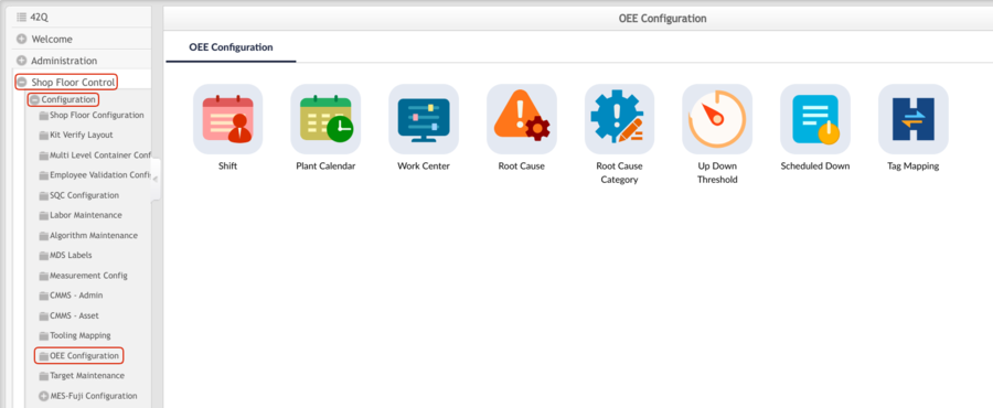
OEE Configuration Main Menu
Navigator to Shop Floor Control > Configuration > OEE Configuration.
Figure 1: OEE Configuration Main Menu
Shift 
The Shift submodule is utilized by supervisory personnel to define the time and days of operation for the various shifts operating in their plants in order to accurately measure OEE Configuration availability. Administrators assign Shift Names and Shift Codes to scheduled shifts and edit and add shifts as needed.
- Navigate to Shop Floor Control > Configuration > OEE Configuration > Shift. The Shift’s main page displays.
Figure 2: Shift Main Page
- Users may Add, Edit and Enable/Disable the shift, and search for shifts using the following filters:
- Shift Name
- Shift Code
- Active
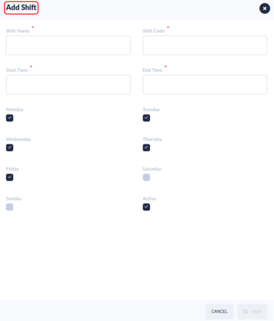
Add Shift
- Select the Add button on the top menu bar to create a new shift entry.
Figure 3: Add Shift
- The following fields are available:
- Shift Name: Provide a name to differentiate the Shift.
- Shift Code: Provide a Code for the Shift.
- From Time: Note the Shift’s start time with the drop-down calendar provided.
- To Time: Note the Shift’s end time with the drop-down calendar provided.
- Workdays: Select all days that have shifts assigned. Available days are Monday - Sunday.
Note: Monday-Friday is selected by default.
- Active: Mark active shift days by activating the checkmark. Shifts marked as active are enabled in the system. The default selection is Active.
Note: The shifts support full hour, half an hour, and non-full hour schedules.
For example:
- Shift 1 - 00:00 to 06:00
- Shift 2 - 06:00 to 17:30
or
- Shift 1- 00:00 to 06:45
- Shift 2 - 06:45 to 17:30
Users need to update the minutes (for example 06:45) manually.
Edit Shift
- Select one Shift from the list then click Edit to open the Edit Shift page.
- Change the Shift Name, Shift Code, From Time, To Time as needed.
- Change the workdays: A Checkbox signifies there is a working shift assigned to the day. Change the Active status as needed. When the checkbox is selected the shift is active status.
- Click Save to save the changes of shift or Cancel to leave the Edit Shift page.
Activate/Deactivate Shift
Sometimes, the users may need to change the existing shifts. For example, the users have shifts 1 to shift 12 with a time period of 2 hours each shift, but want to change them into three shifts as Shift 1 from 06 to 14, Shift 2 from 14 to 22, and shift 3 from 22 to 06.
As other tables may reference those old/inactive shifts, so it is not recommended to delete them physically from the database, users can disable the old shifts and create new shifts.
The main page will list out those active shifts by default in the screen, and add more filter fields in the search panel so users can see all shifts if they need them.
- Select the desired shift by double-clicking on the line of data.
- Select Activate/Deactivate to change the shift status from active/inactive into inactive/active.
Plant Calendar 
The Plant Calendar is a planning tool that allows administrators to add or remove special shifts from the work schedule (such as holidays, or extra workdays, e.g. Sundays), without affecting the regular work shift calendar.
Note: Plant Calendar is not a standard monthly view calendar.
- Navigate to Shop Floor Control > Configuration > OEE Configuration > Plant Calendar to access the plant calendar main page.
Figure 4: Plant Calendar Main Page
- Users are able to view the plant calendar by Location, Production Line or by Asset.
- Users are able to view the plant calendar by Day, by Week, or by Month.
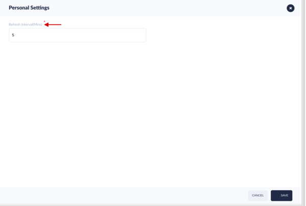
Users can define the refresh time for the plant calendar view.
- Select the tool menu button
 located at the top left section of the calendar.
 - Input the Refresh Interval(Mins) at the personal setting page.
- Select Save to save the refresh interval time or Cancel to exit.
Figure 5: Personal Setting
Users can select the button ![]() to change the view by location , by production line or by asset.
to change the view by location , by production line or by asset.
Download Plant Calendar
Users can download the plant calendar.
- Select the download
 icon.
icon. - The plant calendar lists which meet the current conditions, such as by Week and by Asset will be downloaded as a csv file.
Bulk import Plant Calendar
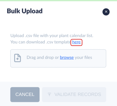
Users can bulk import the plant calendar.
- Select the Upload
 , then the Bulk Upload page will show.
 - Select the here(link) to download the template file, then edit your own plant calendar file.
- Select the browse(link) to upload the plant calendar file.
Figure 6: Bulk Import
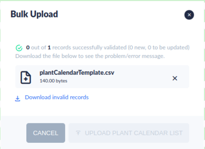
- Select the VALIDATE RECORDS to validate the plant calendar data.
- If there are invald records, users can download invalid records to view or correct.
- If there is no invald record, users can import the bulk plant calendar list into the OEE system.
Figure 7: Download Invalid Records
Notes:
- The asset affected priority for Plant Calendar is higher than the Shift. i.e. If the users make a change in the Plant Calendar, it will override the shift.
- The configuration in the Shift or Plant Calendar will only affect the assets in Running/Spare status. i.e. If the user changes the asset status to other statuses manually like reporting an event of “UnScheduled down” or creating a Repair Work Order without checking “non-stop”, the shift or plant calendar will not take effect. In that case, the user needs to change the asset’s status to running/spare first, and then the asset will run by the shift or plant calendar.
- Once the assets and shop floor location is mapped, the running/spare assets will auto-start or auto-stop according to the shift and the Plant Calendar. And the shift will affect all the running/spare assets that have been set to AssetMapping in the site.
Please see the How to Make Asset Auto-start/Auto-stop by the shift for details.
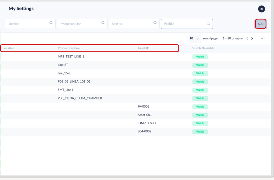
My Settings
Users can view the special calendar for themself adding the associated plant calendar by location , by production line or by Asset.
This is an important step to define your own plant calendar view.
- Select My Settings to manage your own plant calendar view.
- The My settings page shows.
Figure 8: My Settings
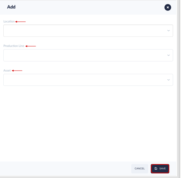
- Select ADD.
- Select the Location , Production Line or Asset from the drop-down menu.
- Select Save.
- The plant calendar for the location/production line/asset will show on the plant calendar main page.
Figure 9: Add My Settings by Location/Production line/Asset
Change the shift status
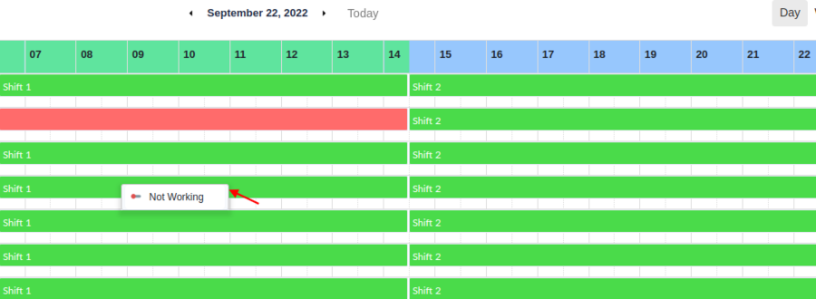
Users can change the status to Working or not Working for the not started (future) calendar.
- Right click on the shift list, then the right menu will show.
Figure 10: Right menu
- Select the Not working or Working.
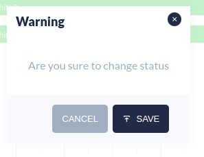
- Select the Save to change the status or Cancel to exit.
Figure 11: Warning to Confirm
Manage Plant Calendar
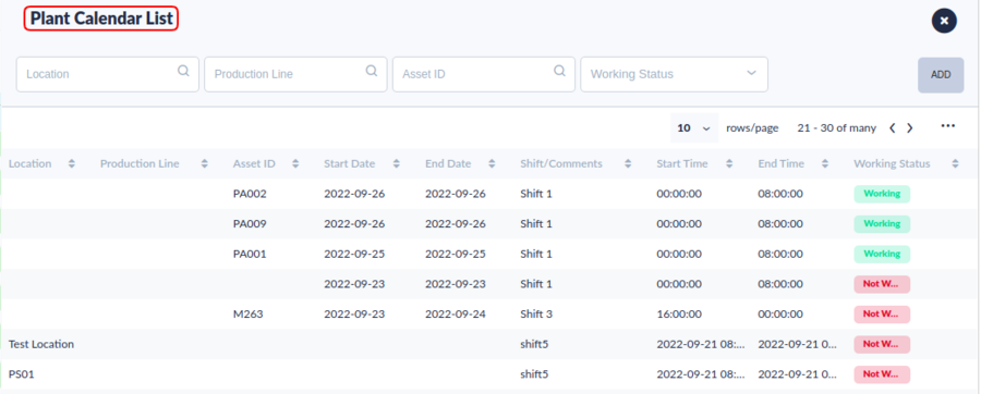
In this module,users can Add, Edit, Delete and Search the Plant Calendar by Location, Production Line, Asset or Status
Figure 12: Plant Calendar List Main page
Add Plant Calendar
- Select the Add button to open the Add Form.
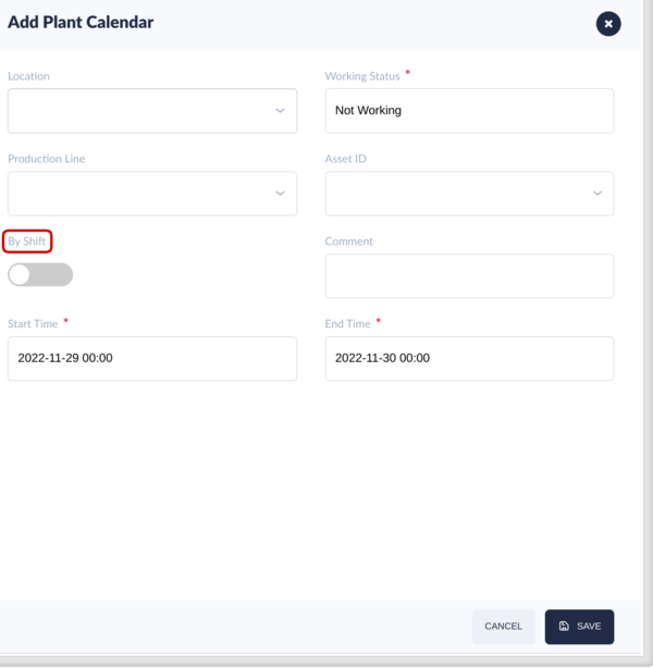
Figure 13: Add Plant Calendar by Shift
Figure 14: Add Plant Calendar not by Shift
- Select the Location (optional ) and Production Line(optional) using the drop-down list provided.
- Select the Working if the shift is scheduled to work on the given date or Not Working if the shift is off duty on the selected date for the Working Status drop-down list.
- Select the Asset ID(optional) from the drop-down list.
- Select the By Shift in active status and Shift using the drop-down menus provided.
- Or Select the By Shift in inactive status and select the From Date, To Date, Start Time, End Time.
- Select Save to save the new plant calendar, or cancel to exit the add form.
Edit Plant Calendar
- Select the Plant Calendar for modification then select the Edit icon to open the Edit Form.
Figure 15: Edit Plant Calendar Icon
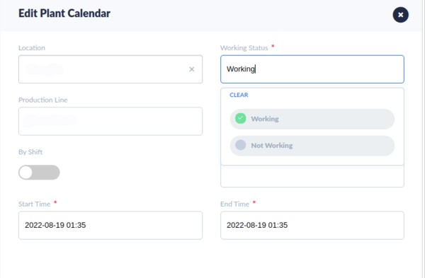
Figure 16: Edit Plant Calendar
- Change the Location, Production Line, Asset ID, and Shift Date.
- Select Working if the shift is scheduled to work on the selected date; Not Working if the shift is off duty.
- Click Save to save the changes in the plant calendar, or cancel to exit the edit form.
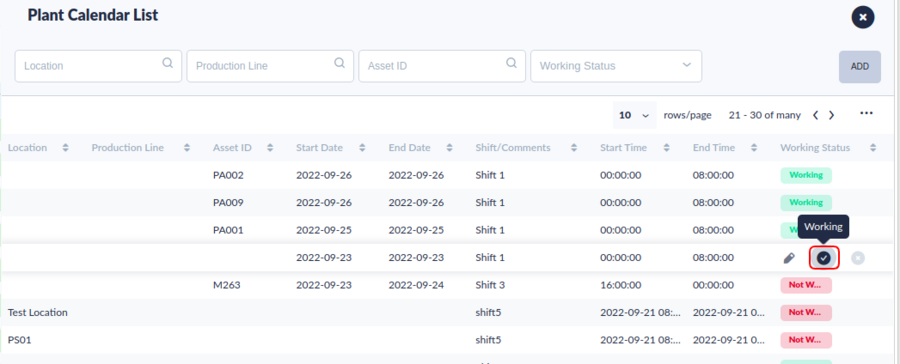
Change the Working Status for Plant Calendar
- Select the Plant Calendar, then click the Working/Not Working button.
Figure 17: Change Plant Calendar Working Status
- A message will display at the top for the plant calendar status changing.
Work Center 
The Work Center defines a group of machines that build the same product on a production line or shop floor. Work Center is a configuration tool used by managers to:
- Designate the Work Center Name
- Assign an Asset to the Work Center.
Assigning the asset is a critical step that allows data to move between portals within the MES system, thus providing superior traceability and data collection.
Note: Assets are configured within the CMMS Asset portal (Shop Floor Control > Configuration > CMMS Asset).
- Navigate to Shop Floor Control > Configuration > OEE Configuration > Work Center to access the Work Center’s main page.
Figure 18: Work Center Main Page
- Users can Add, Edit, Delete and search the Work Center.
Add Work Center
- Select the ADD to open the add form.
- Enter the Work Center name
- Select the Asset ID for the machine running on the work center.
- Select the Save button to add the new Work Center or Cancel to exit the field.
Edit Work Center
- Select one Work Center from the list then click Edit to open the Edit Form.
Figure 20: Edit Work Center
- Change Work Center or Asset ID as needed.
- Select Save to save the updates, or Cancel to close the edit form without saving.
Delete Work Center
- Select the Work Center, then click Delete.
Figure 21: Delete Work Center
- A Message window displays asking the user to confirm the action.
- Click Yes to delete the Work Center, or click No to cancel.
Root Cause
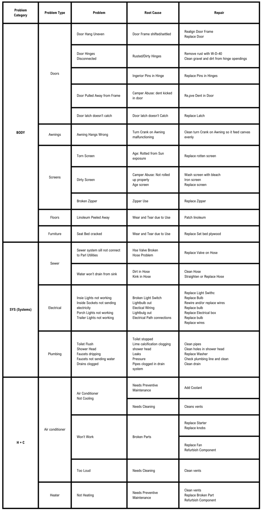
Users may add and edit root causes directly from the Root Cause Category submodule explained previously, or within the Root Cause submodule of OEE Configuration. It is important that a direct relationship between Root Causes and Root Categories exist.
![]() TIP: Chart Root Cause Categories and Root Causes in a table or spreadsheet first.
TIP: Chart Root Cause Categories and Root Causes in a table or spreadsheet first.
Examples of root causes pertaining to a manufacturing environment include: Material Issues, Shortage of Operators, Unscheduled Maintenance, Change Over, End of Shift Cleaning, and Tool Change.
Note: Selecting exact root causes assists engineering teams in troubleshooting machine downtimes, thereby creating strong OEE Configuration data to achieve optimal asset productivity.
Add Root Cause 
To create a new Root Cause:
- Go to: Shop Floor Control > Configuration > OEE Configuration > Root Cause.
Figure 22: Root Cause Main Page
Bulk Upload Root Cause
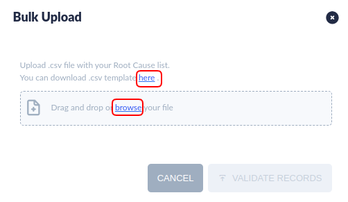
With the Bulk Upload root cause function, users can import(create/add) many root causes at one time. This function involves downloading the template file, uploading the file and validating whether the data is valid. Users can download the invalid records to check and correct.
- Select the BULK UPLOAD , the Bulk Upload window pop-up.
Figure 23: Bulk Upload Root Cause
- Select the here(blue link) to download the .csv template file and fill your assets records if you do not have the template file.
- Drag and drop or select browse(blue link) to open your file.
- Select VALIDATE RECORDS, the UPLOAD button will show if the validation process passed.
- Select Upload to save the root causes records to the system.
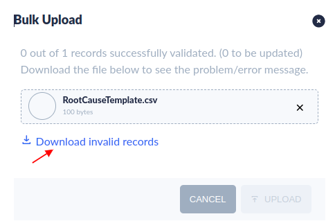
- Select Download invalid records to download and check the invalid records if some records are invalid.
Figure 24: Download invalid Records
Add Root Cause
With the Add Root Cause function, users can create/add root cause one by one.
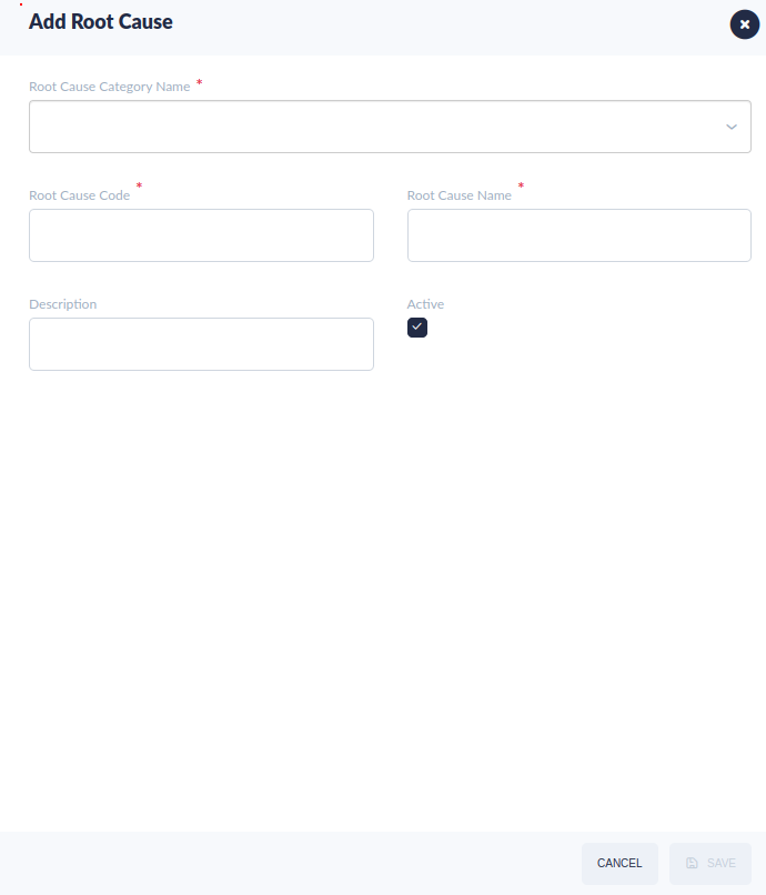
- Select the ADD ROOT CAUSE button.
- The Add Root Cause window displays the following options:
- Root Cause Category (Mandatory) Select the appropriate category from the drop-down menu. Categories are listed as icons in a tree format according to parent/child relationship.
- Root Cause Code (Mandatory) Enter the Root Cause Code into the text field.
- Root Cause Name (Mandatory) Enter the Name of the Root Cause in the text field.
- Description (Optional) Add any additional instructions that may be necessary.
- Active (Checkmark) Select the checkmark to activate the Root Cause.
Figure 25: Add Root Cause
Edit Root Cause
To edit a Root Cause:
- Select the Root Cause from the Root Cause list.
- Modify any of the fields:
- Root Cause Category: Select a different category from the drop-down list.
- Root Cause Code: Change the Code for the Root Cause selected.
- Root Cause Name: Change the Name of the Root Cause selected.
- Description: Add or change the description.
- Active: Change the status of the root cause by activating or deactivating the checkmark. Active = Checked.
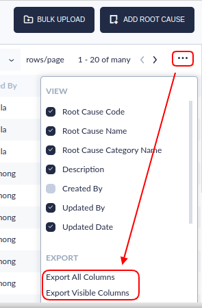
Export Root Cause
Users may also Export Root Cause information for quick access from a local pc or laptop.
- Select the ...
- Select the Export All Columns or Export Visible Columns.
- The data automatically downloads in a .csv file onto the user’s local drive and is available to save, print, or share as desired.
Figure 26: Export Root Cause
![]() TIP: Find more information about the relationship between problems, root causes, and repairs in the chart in this document RV Rental Problem/Root Cause/Repair Example.
TIP: Find more information about the relationship between problems, root causes, and repairs in the chart in this document RV Rental Problem/Root Cause/Repair Example.
Root Cause Category 
Root Cause Categories are broad descriptions of machine downtime problems. Possible manufacturing Root Cause Category examples includes: Process, Energy, System, and Maintenance. Engineers may also add new root causes or edit associated root causes from the Category submodule.
Root Cause Categories are organized in a parent/child hierarchy in a visual tree format. Main categories are represented by yellow folders (parents); blue file folders represent subcategories (children).
- Navigate: Shop Floor Control > Configuration > OEE Configuration > Root Cause Category.
- To add/edit a category, select the category’s location within the hierarchy by right-clicking on the parent or child icon. A pop-up window displays, which allows the user to Add a new category or Edit the selected category.
Figure 27: Add Child Root Cause Category
Add Root Cause Category
- A new window displays, with the following fields available for entry (see figure, below):
- Root Cause Category Name (Mandatory)
- Root Cause Category Code (Mandatory)
- Description (Optional)
- Select the Add icon to save the new root cause category as a “child” to the selected “parent” Root Cause.
![]() TIP: Users can add corresponding Root Causes directly to Root Cause Category in Edit mode.
TIP: Users can add corresponding Root Causes directly to Root Cause Category in Edit mode.
- GENERAL NOTES about Categories:
- Parent folders are denoted by a yellow folder icon.
- Child folders are denoted by a blue folder icon.
- Users may not add more than 5 levels to one root cause category.
- Only active Parent categories (denoted by a blue checkmark in the Active column) are available for edit. Likewise, children's categories cannot be added to inactive parent categories.
- Children's categories display indented beneath their parents.
- If a second child category is added to the first child, its position moves to the left side of the screen to signify parent hierarchy (and changes to the yellow file folder icon).
Figure 28: Add a New Root Cause Category Pop-up Window
Edit Root Cause Category
To edit a Root Cause Category:
- Click on the root cause to activate the Edit Root Cause Category window.
- Modify any of the fields:
- Parent Root Cause Category: Select a different category from the drop-down list.
- Root Cause Category: Select a different category from the drop-down list.
- Root Cause Category Name: Change the Name of the Root Cause Category
- Root Cause Category Code: Change the Code for the Root Cause Category
- Description: Add or change the description.
- Active: Change the status of the root cause category by activating or deactivating the checkmark. Active = Checked.
Edit Root Cause
Root Causes associated with the selected category may also be vieweddirectly from the Root Cause submodule.
Figure 29: Edit Root Cause Category: Root Cause
Activate/Deactivate Root Cause Category
To change the status of a Root Cause Category:
- Select the Root Cause by activating the checkmark.
- Select Activate or Deactivate.
Tag Mapping 
The Tag Mapping feature links (tags) assets to the OEE Configuration reporting system. This mapping process allows 42Q's MES to automatically capture asset downtimes and problems from CMMS and eliminates the need to manually input downtime events. Once a downtime event is received, the system creates a new repair Work Order or closes the corresponding Work Order in CMMS.
Go to: Shop Floor Control > Configuration > OEE Configuration > Tag Mapping. Users may search, add, edit, or enable/disable a Tag ID via the Tag Mapping submodule.
To connect your factory’s standalone equipment (e.g. sensors), see Rapid IIoT
Figure 30: Tag Mapping Submodule Location
Downtime Data Flow
Once mapped, 42Q captures and sends downtime data to multiple systems within the 42Q family.
Asset is Down → Downtime data is sent to OEE Configuration → OEE Configuration sends data to MESWeb Reports → MESWeb Reports creates reports → Real-time data is displayed directly on the factory floor via Operation Dashboard.
Tag Ids are set according to Error Code or Up/Down in OEE Configuration and are configured in CMMS Asset according to Problem Type.
Search/Filter Tag ID
Users may search assets mapped to OEE Configuration according to the filters located on the top menu bar: Tag ID, Asset ID, Tag Type, or Asset Status.
Bulk Upload Tag Mapping
With the Bulk Upload function, users can import(create/add) many tag mappings at one time. This function involves downloading the template file, uploading the file and validating whether the data is valid. Users can download the invalid records to check and correct.
- Select the BULK UPLOAD , the Bulk Upload window pop-up.
- Select the here(blue link) to download the .csv template file and fill your assets records if you do not have the template file.
- Drag and drop or select browse(blue link) to open your file.
- Select VALIDATE RECORDS, the UPLOAD button will show if the validation process passed.
- Select Upload to save the tag mapping records to the system.
- Select Download invalid records to download and check the invalid records if some records are invalid.
Add Tag ID
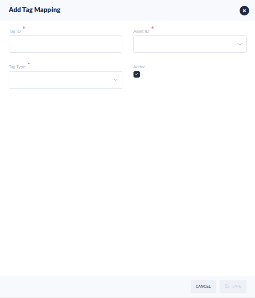
- Select ADD TAG MAPPING from the top menu bar.
- Complete the fields in the pop-up window:
- Tag ID: The unique Tag the Client will use to send data to 42Q’s API. The Tag ID is the identifier that links the CMMS Asset to OEE Configuration and allows the system to automatically create and close Repair type Work Orders.
- Asset ID: Select the Asset ID from the drop-down menu. This mapping allows CMMS and OEE Configuration to interface with each other. (NOTE: Asset IDs are configured in CMMS Asset: Shop Floor Control > Configuration > CMMS Asset).
- Tag Type: Select the Tag Type from the drop-down list. There are five options: Error Code , Up/Down , Power, Gas and Water. Default is Error Code.
- Error Codes (Problems): Select Error Codes to send downtime error codes from Assets to the Client to CMMS and OEE Configuration.
- See also: CMMS Asset > Asset Mapping.
Note: In order for the Client to send downtime errors to OEE Configuration, Error Codes must first be configured in CMMS as a Problem Code. Error Codes are determined by the software used by the Client. Check with your local development team for the list of Error Codes used by your plant’s Client, then configure the Problem Code in CMMS Asset > Problem Type so the systems connect.
- Up/Down: Select Up/Down if the data being collected is for the purpose of determining the asset’s Availability (downtime) only. (e.g. Is this asset running or stopped?).
- Up signals = 0/True
- Down signals = 1/False
- Status: Mark the Tag ID is active (checked) or inactive (unchecked). Default is active (checked). NOTE: Marking the Status as inactive removes connectivity between OEE Configuration and CMMS.
Note: Some Clients do not have the ability to capture Error Codes - they can only capture up or downtimes. For this situation select Up/Down. Check with your local development team about Client capabilities and features.
- Select Save to add the new Tag ID or Cancel to exit the field.
Figure 31: Add Tag Asset Mapping
Edit Tag ID
To modify a Tag ID:
- Select the Tag ID by highlighting the line of data.
- Select Edit from the top menu bar.
- Change any of the fields using the pop-up window.
- Select Save to save changes or Cancel to exit the field.
Activate/Deactivate Tag ID
To change the status of a Tag ID:
- Select the Tag ID by highlighting the line of data.
- Select Activate/Deactive from the top menu bar.
Figure 32: Activate/Deactivate Tag Asset Mapping
![]() TIP: For more details about Error Codes and Up/Down Signals read this document: How_to_use_42Q_MES_OEE_module.
TIP: For more details about Error Codes and Up/Down Signals read this document: How_to_use_42Q_MES_OEE_module.
Schedule Regular Downtimes According to Problem in CMMS
Plants using MES101 automatic data collection can record regularly scheduled downtimes (such as lunch breaks) through the Problem module in CMMS Asset. Follow these steps:
- Move to CMMS Asset > Problem.
- Select Add.
- Complete all the fields.
- Note: Users will first need to create a Problem Category and Problem Type.
- Select: Scheduled Down.
- Select Active.
- Alternatively, breaks can be added as a Global Problem if the entire plant will take the same amount of time for lunch.
Up/Down Threshold 
The Up/Down Threshold submodule of OEE Configuration allows engineers to set a grace period (threshold time) before assets are officially flagged as down or up in the 42Q MES.
Up/Down Thresholds are configured according to Asset Type and depend upon that machine’s unique running patterns and idiosyncrasies. The time selected will determine how long the system allows before machine stoppages and starts are recorded as down/up times. Time intervals are available in minutes, seconds, or milliseconds.
Example: Down Threshold
Machine A stops for one minute between each cycle to rotate to new trays. If the system captured each one minute stop as part of the OEE Configuration downtime data, that data would inaccurately reflect low Performance rates. To counteract the problem, engineers might set the Down Threshold for Machine A to 2 minutes. This way normal process downtime will not adversely affect the OEE Configuration calculation or show as downtime events.
Figure 33: Up/Down Threshold Main Screen
Search/Filter Up/Down Threshold
- Users may search according to the following criteria, located on the top menu bar of the Up/Down Threshold submodule:
- Asset ID: Select the Asset from the drop-down list provided.
- Asset Type: Select the asset type from the drop-down menu provided.
- Choose the search icon (e.g. magnifying glass).
Bulk Upload Up/Down Threshold
With the Bulk Upload function, users can import(create/add) much Up/Down Threshold at one time. This function involves downloading the template file, uploading the file and validating whether the data is valid. Users can download the invalid records to check and correct.
- Select the BULK UPLOAD , the Bulk Upload window pop-up.
- Select the here(blue link) to download the .csv template file and fill your assets records if you do not have the template file.
- Drag and drop or select browse(blue link) to open your file.
- Select VALIDATE RECORDS, the UPLOAD button will show if the validation process passed.
- Select Upload to save the tag mapping records to the system.
- Select Download invalid records to download and check the invalid records if some records are invalid.
Add Up/Down Threshold
- Select Add from the top menu bar.
- Complete the following fields in the pop-up window provided:
- Asset ID: Select the Asset ID from the drop-down menu provided. (Note: Assets are configured in the CMMS Asset portal: Shop Floor Control > Configuration > CMMS Asset).
- Asset Type: Select the Asset Type from the drop-down menu provided. (Note: Asset Types are configured in theCMMS Asset portal: Shop Floor Control > Configuration > CMMS Asset).
- Up Threshold: The amount of time allowed before the asset is reported up and running after stoppages. (e.g. repair and/or setup time needed following downtime). Select the time interval using the drop-down menu provided.
- Down Threshold: The amount of time (grace period) allowed before the machine is reported down. This is especially useful when DMIs are employed to collect asset data. If the program does not receive a run signal by the defined down threshold, technical engineers must enter the reason for downtime. Select the time interval using the drop-down menu provided.
- Unit: Select the unit of time from the available options: Minutes, Seconds, Milliseconds. Minutes are selected by default.
Figure 34: Add Up/Down Thresholds
Edit Up/Down Thresholds
To modify an Up/Down Threshold:
- Select the Up/Down threshold by highlighting the line of data.
- Select Edit from the top menu bar.
- Change any of the fields using the pop-up window.
- Select Save to save changes or Cancel to exit the field.
Schedule Down 
From the Scheduled down module, the plant users will be able to record the schedule time into the OEE system as follows:
- Record the scheduled downtime and the reason/problem by location, production Line or individual asset.
- Record the scheduled downtime with the start time, duration and different time unit, such as Minute, Hour, Day.
- Record Every value & Repeat Type, such as Day, Week, Month.
- Record the From Date & End Date for the scheduled down period.
- Filter the scheduled downtime list by Location, Production Line, Create By, Asset ID, Update By.
To access Schedule Down navigate to Shop Floor Control > Configuration > OEE Configuration > Schedule Down.
Figure 35: Schedule Down Main Page
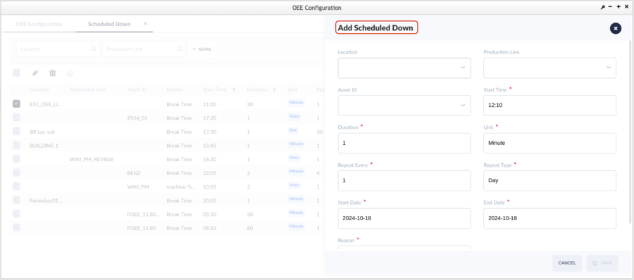
- Select Add button to Add the schedule downtime.
Figure 36: Add schedule downtime
- Enter the associated items then select the Save to add one scheduled downtime.
- The Items follows:
- Location: Select the Location from the drop-down list.
- Production Line: Select the Production Line from the drop-down list.
- Asset ID : Select the Asset ID from the drop-down list.
- Start Time: Enter the start time for the scheduled downtime activity.
- Duration: Enter the time how long that the scheduled downtime activity will last.
- Unit: Unit of time,there are three options: Minute, Hour,Day.
- Repeat Every : If the scheduled down activity did not happen one time, users can define the repeat rate.
- Repeat Type: There are three options : Day, Week, Month.
- From Date: Select the Start date for the scheduled down activity.
- To Date : Select the end date for the scheduled down activity.
- Reason: Select or Input the Reason for the scheduled down activity.
- Users can edit or delete the configured schedule down activity.
- Select the record, check the checkbox at the left, then select the Edit or Delete.
Figure 37: Edit or Delete Schedule Down
Configure OEE Configuration Target Values
As the OEE features:
(1) 42Q Live/Operation Dashboard/OEE Dashboard to identify the OEE health status, such as Green, Yellow, Red.
(2) MTBF And MTTR Report
that require the values of the OEE Target fields, so users need to configure the OEE target values.
OEE Configuration interfaces successfully with the following systems to capture cycle time data from plant assets:
- Oracle ERP systems push cycle time data from MSD plants.
- Target Maintenance modules integrate cycle time data.
To meet the requirements of a wide variety of plants, OEE Configuration offers two ways to configure target data/Target UPH.
- Plants using MES 101 can set target values at the Target Maintenance module;
- Plants that utilize Oracle’s ERP to transfer data define target values in Oracle; 42Q sends data via the Oracle Work Order to 42Q’s Shop Order.
Following will describe the second method to set the Target UPH.
Configure Source Type
42Q locates the data source by a tag field/column target UPH source type. Source types are based on the plant’sOEE Configuration Solution . Source Types are configured on the backend by the MES support team. Following is a brief description of each source type.
Source_type data field value will be 1 & 2.
Source_type data field
- 1 - The OEE API will get the SOMS Target UPH values automatically from the MES101, it won’t save the SOMS Target UPH values into the OEE database and it will get the SOMS Target UPH values each time when the OEE is needed.
- 2 - To get Target UPH values automatically for plants using the MES system in conjunction with Oracle’s database. The system will collect the Target UPH from the Oracle database accordingly.
Note: The source_type 1 is for all the general plants, the scource_type 2 is specific for the Enclosure plant with the ERP interface to sync the Target UPH value.
Target Configuration for MES 101 Plants
Plants using OEE Configuration in conjunction with MES101 will set target UPH values in 42Q’s Target Maintenance module.It won’t save the SOMS Target UPH values into the OEE database and it will get the SOMS Target UPH values each time when the OEE is needed.
Configure Target Data
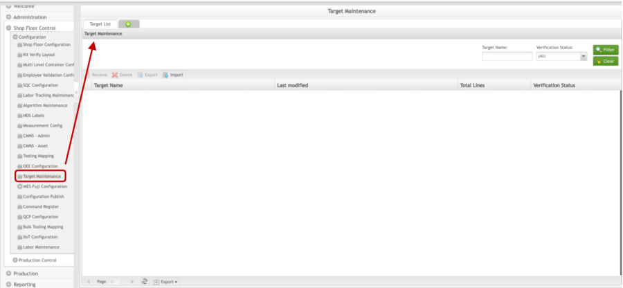
- Navigate to: Shop Floor Control > Configuration > Target Maintenance.
Figure 38: Target Maintenance Main Page
- Refer to the Target Maintenance User Manual for more details.
- Follow the examples below to configure:
- Target data for MFG Lines → SOMs Target
SOMS Target: Define Target
The SOMS Target is used to configure target data according to the Process, Part Number, or Part Family and location. The configuration also determines how MES 101 data (e.g. target yields, throughputs, top defects, etc.) will be displayed in Operation Dashboard and 42Q Live.
In addition to the target values available for configuration in the OEE Configuration Target, the SOMs Target allows users to define cycle times according to the complexity of each product built on a manufacturing line. Users create this association by selecting Part Number or Part Family in the SOMS Target.
The system has the option to define the target UPH for specific or generic by Part/Family/Location or by Part/Family/Process.
- Locate the SOMS-Target spreadsheet by utilizing the filter feature in the top menu bar of Target Maintenance.
Please see the How to Set Target for OEE for more information.
- Upload the completed template into the MES database from the Target Maintenance module.
- Target values can be defined for all categories included in the SOMs Target List (see bulleted list below).
- See also Operation Dashboard Wiki documentation for more details about each field.
- Part Number: The unit part number. (50 Character Limit). User can define the Part Number at Shop Floor Control > Configuration > SFDC Configuration portlet. As a general rule, the part number should match the Oracle part number.
- Family: Define the Target values for that Product Family. Defines a part number for use as a "Part Family" to associate other part numbers to. The user must first create a Part Family before adding parts to it.
- Process: Process is a series of actions or steps taken in order to achieve a particular end. The Process name is defined in the SFDC Configuration module. For example: Scrap Repair.
- Work Station: To define the target value ofr the workstation or location.
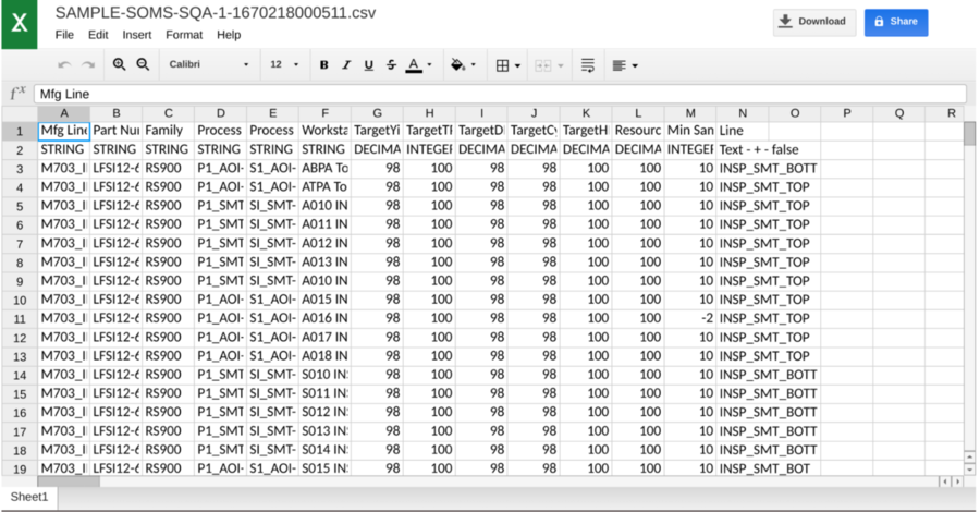
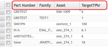
- TargetTPhr: = Target UPH.
Figure 39: An example for Target Maintenance - SOMS Target .csv file
Important Note: The column TargetTPhr = Target UPH.
- Add the completed SOMS Target .csv file into MES database from the Target Maintenance module.
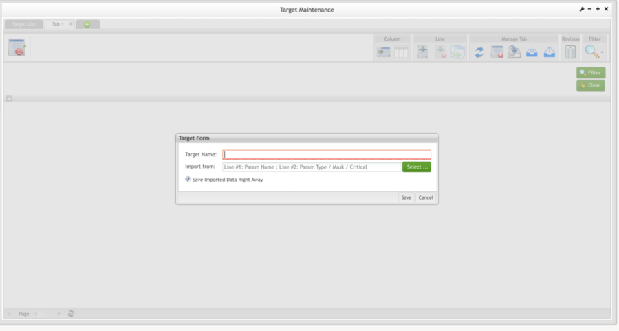
- At the Target Maintenance main page, click the Add icon to add a new Target.
Figure 40: Target Maintenance Add Target Form
- Enter the Target Name in the Target Name text field.
- Click Select to open and select the prepared SOMS Target .csv file.
- Click Save.
- A Success message will display.
Figure 41: Target Maintenance - SOMS Target
Note: The SOMS target supports the Part number/Location and Part Family/Location to define the Target UPH,as the above screenshot. When users try to use the part family target UPH, the Part number column could set as false or empty.
For example: Part Number p1,p2,p3,p4,p5,p6 have the same part family F1, and the Target UPH for the part family F1 is 50, which means all the Part numbers for this part family have the same target UPH. Users just only need to append one line something as below the table.
| Mfg line | Part Number | Family | Workstation | Target UPH |
| Line1 | false or empty | F1 | P1 | 50 |
The users can define the target UPH by both Location and process at SOMS target, then the system will find out the correct location or process based on the following SOMS target priority rules.
- Priority 1: Part number & Location.
- Priority 2: Part number & Process.
- Priority 3: Part Family & Location.
- Priority 4: Part Family & Process.
Scenario 1: Set the Family ID and Process value at SOMS_target , the system will define thetarget UPH based on Family ID & Process. If the SOMS_target has noPart number then the system will use Family ID. If the SOMS_target has no Workstation(Location), then the system will use Process.
Scenario 2: Family ID & Process & Workstation(Location) - it will define the target UPH based on Family ID & Workstation(Location). If the SOMS_target has no Part Number, then the system will use the Family ID. If the SOMS_target has both Process and Location, then the system will use Location.
Scenario 3:Family ID & Part Number & Process - it will define the target UPH based on Part number & Process. If the SOMS_target has both Part number and Family ID, then the system will use the Part number. If the SOMS_target has no Workstation(Location), then the system will use Process.
Scenario 4: Family ID & Part number & Process & Workstation(Location) - it will define the target UPH based on Part number & Workstation (Location).
Note: From 15.76, the system supports defining the target UPH at asset level for the SMT AOI Machine API target UPH method as follows.
Figure 42: Asset level- SOMS Target
Priority 1: Part number & Asset.
Priority 2: Part Family & Asset.
Priority 3: Asset.
Scenario 1: Set the Part Number, Family ID and Asset value at SOMS_target , the system will define the target UPH based on Part Number & Asset. If the SOMS_target has no Part number then the system will use Family ID.
Scenario 2: Family ID & Asset - it will define the target UPH based on Family ID & Asset. If the SOMS_target has Part Number, then the system won’t use the Family ID.
Scenario 3: Asset - it will define the target UPH based on Asset. If the SOMS_target has no both Part & Family ID, then the system will use the Asset.
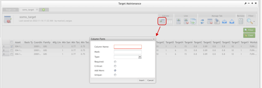
Edit Columns in a Table
Users may Add or Delete columns and lines in any Target Maintenance Table.
Figure 43: Edit Target Maintenance Tables
View Target Maintenance History
A complete history of every entry in Target Maintenance is available by selecting Revision 
MESWeb/OEE Configuration Dashboard Target
Use the Table OEE Configuration_Target to define how to target data will display in MESWeb reports, the OEE Configuration Layer in 42Q Live, and Operation Dashboard.
- Download the template provided in .csv format.
- Target values can be defined for all categories included in the template’s individual headings (see bulleted list below).
- Add target values as required for your individual plant.
Note: Users can add/delete the columns/lines according to their individual production needs.
- See also Operation Dashboard Wiki documentation for more details about each field.
Define Mapping between Reason Code/Error Code and CMMS Problem Code
The OEE Configuration system provides APIs/Interfaces to get Downtime Reason/Error Codes from PLCs and Up/Down data with Error Codes from FUJI equipment automatically.
To use the MES Agent application to send Fuji data directly to 42Q's OEE Configuration, users must first create a mapping between Reason Code/Error Code and the CMMS Problem Code from the OEE Configuration GUI. Several configurations in the CMMS portal are required before completing the necessary mapping in OEE Configuration.
- Define the Problem in CMMS (Shop Floor Control > Configuration > CMMS - Asset > Problem).
- Map the relationship between Problem and AssetType: (CMMS Asset > Asset Type).
- Select the Asset Type using the Edit GUI.
- Select the Problem Tab in the popup window.
- Return to OEE Configuration > Tag Mapping to map the relationship. See Tag Mapping.
- Each Module of one Fuji Machine can be treated as one tag.
- To create a Tag ID for Fuji equipment use this naming convention: Tag ID = Fuji machine name + Module #
- Link each Module to the CMMS Asset.
- Similarly, users must also map Reason Codes to Problem Codes for the PLC.
Figure 44: Set mapping relationship between Problem and Asset Type
Glossary of Terms
- Availability: Machine Downtime, according to duration. Takes into account all machine downtime including minor stoppages, slow production, and idling. Calculated as: Operation Time/Planned Production Time = Availability.
- Client: Firmware, software, or hardware system used to capture and send data from assets on the factory floor to the 42Q API. Commonly used clients include Fuji AIMEX and PLCs. This concept is directly connected to Rapid IIoT.
- Cycle Time: (Time/Hours per Unit) is the time it takes to produce 1 unit in the (UPH) process. Cycle time and UPH metrics are dependent. One is a function of the other. Cycle Time is the hours per Unit.
- KPI: Key Performance Indicators
- Loading: This represents the percentage of time that an operation is scheduled to operate compared to the total Calendar Time that is available. Calculated as: Scheduled Time/Calendar Time = Loading
- MESAgent: An application used to collect Fuji data for the 42Q OEE Configuration system (MESAgent, Fuji-OEE Configuration interface).
- MTBF: Mean time between failures (MTBF) is the predicted elapsed time between inherent failures of a system during operation.
- MTTR: Mean time to failure (MTTF), measures the average time between failures.
- OEE Configuration: Overall Equipment Effectiveness is a manufacturing metric that identifies the percentage of productive manufacturing time according to Quality, Performance, and Availability. It is the single best metric for identifying losses, benchmarking progress, and improving the productivity of manufacturing equipment. Calculated as: Availability x Performance x Quality = OEE Configuration
- Performance: A measure of productivity, specifically the speed at which parts are built. Calculated as: Actual Rate/Standard Rate = Performance
- PLC: Programming Logic Control
- OPC Server: Open Platform Communication Servers
- Quality: The percentage of parts that meet quality standards without rework. Calculated as: Good Units/Total Units = Quality
- Target Yield: The ideal yield for a given asset, against which the actual yields are measured; critical status is displayed based on the comparison of target yield and actual yield.
- TEEP: Total Effective Equipment Performance. Calculated as: Loading x OEE Configuration.
- Throughput: Units per Hour.
- UPH: (Units Per Hour) is a throughput metric portrayed as a number. UPH is typically assigned to high-volume processes. Answers the question: How many units are built in this process per hour?
