42Q-MES0181-A 42Q SAP Adapter Installation Guide
42Q Home > Tools > 42Q SAP Adapter > SAP Adapter Installation Guide
42Q SAP Adapter Installation Guide
Version MES15.79
Bundle Version 32.07.00_15.68.00
Package Version 700_750
Revision C1
Contents
- 1 Overview of 42Q-SAP Interface:
- 2 Pre-requisites:
- 3 Uploading PAT file to Client 000
- 4 Install add-on using SAINT T-Code
- 5 Create the Logical Port to Access the Consumed Service
- 6 Create Binding For Service Providers
- 7 Retry Mechanism and Scheduling Background Jobs
- 8 Maintain /A42Q/LOOKUP
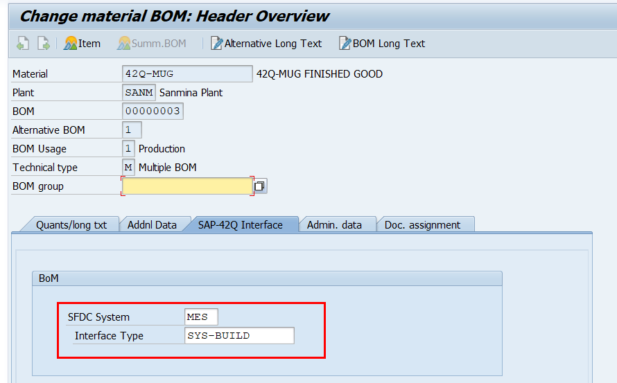
- 9 Material Setup
- 10 Enhancements Implementation
- 11 Roles And Authorizations
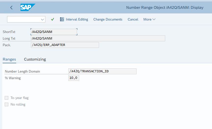
- 12 Assign Number Range For /A42Q/SANM Object
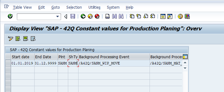
- 13 Setup /A42Q/CONSTANT For Each Plant
- 14 Enhancement Assignment
Overview of 42Q-SAP Interface:
Work Order Integration has the ability to integrate ERP Work Order capability with 42Q to automate and improve the Work Order mapping, release, WIP moves, and completion transactions. This enhances the overall labor efficiency for Work Order management, material,
and financial reporting.
This interface will securely integrate ERP and 42Q through the following main flow:
- Work orders from ERP are fed through a web service interfaced with 42Q.
- 42Q acknowledges that the work orders have been received.
- WIP Move and completion transactions are fed from 42Q to ERP.
- ERP acknowledges the processing of the WIP Move and completion transactions.
Pre-requisites:
- Web Service file of the customer to consume in SAP.
- Verify the Service Endpoint URL in the WSDL file and check the connectivity.
- Check if the SSL certificates are installed for HTTPS. If not, then the correct certs have to be installed using the transaction code: STRUST.
- The 42Q IP addresses need to be whitelisted:
- Local IP: Customer Local IP Address.
- Public IP: Customer Public IP Address.
Required SAP Platforms, Systems and Enhancement Packages:
The SAP system Component (SAP_BASIS) version must be 750 SP1 or higher.
Required SAP Modules:
Below modules are required for the SAP-42Q Adapter:
- SAP Modules
- SAP BASIS
- SAP ABAP
- SAP Production Planning (PP)
- SAP Sales & Distribution (SD)
Required Roles:
BASIS admin roles are required for installing the adapter settings:
Uploading PAT file to Client 000
Upload the 42Q-ERP adapter add-on files to the /usr/sap/trans/EPS/in in the server. Below are the .pat files that need to be uploaded:
- SDV0021167252_XXXXXXXX.PAT
Install add-on using SAINT T-Code
- Log on to client 000 in your SAP system as a user with SAP_ALL rights.
- Enter the T-code SAINT to install the add-on.
- Press the Enter key.
Figure 1: Code Field
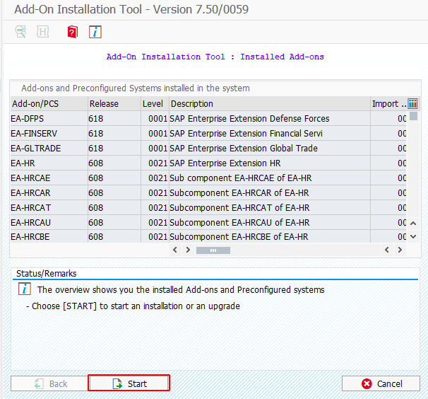
- Select Start to select the add-ons.
Figure 2: Add-On Installation Tool
- Select the Load button to load the package.
- Make sure both Main and Support package .pat files are loaded successfully.
Figure 3: Uploading Packages
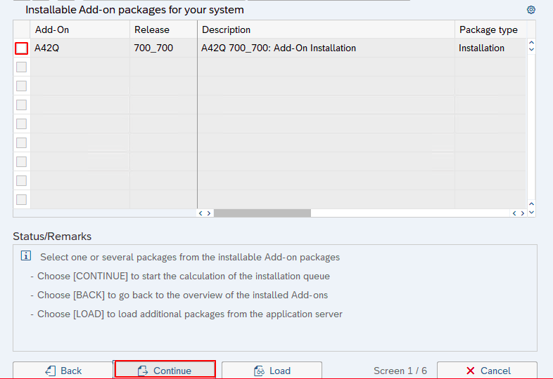
- Select the A42Q add-on Release 700_700.
- Select Continue.
Figure 4: Add-on Selection
- Select the SAPK-701CHINA42Q from the Target Support Package.
- Select Continue until the installation is initiated.
Figure 5: Support Package Selection
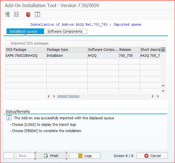
Figure 6: Installation Queue
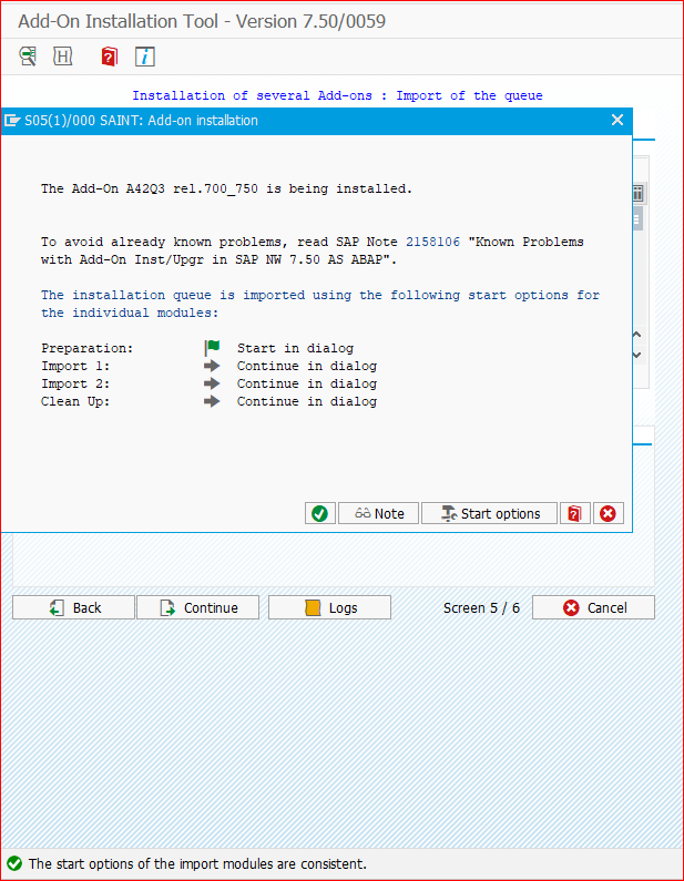
- The below screen confirms that the installation is initiated. Select the green tick button.
Figure 7: Starting Installation
- Once the installation is complete, select Finish.
Figure 8: Installation Complete
Note: The package is now installed successfully and will be available in client 100. The user can now log into client 100 to do further adapter related setups
Create the Logical Port to Access the Consumed Service
- Enter the T-code SOAMANAGER.
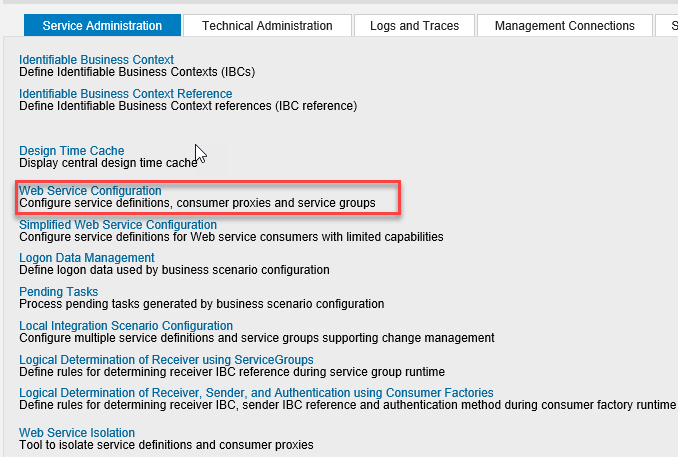
- A new screen will appear in Internet Explorer. Select the Web Service Configuration hyperlink.
Figure 9: Web Service Configuration Hyperlink
- Search for the respective Consumer Proxy name.
- Select the Consumer Proxy and select the Create button.
Figure 10: Web Service Configuration Form
- Enter the Logical Port name.
- Enter the description.
- Select Next.
Figure 11: General Configuration Settings
- Upload the WSDL file provided by the 42Q team.
Figure 12: WSDL Access Settings
- Enter the login User Name (User ID) and Password provided by the 42Q team.
- Select Next.
Figure 13: Configuration of Consumer Settings
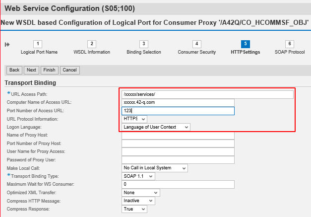
- Update the URL Access Path and Computer Name of Access URL per the information provided by 42Q team.
Figure 14: Transport Binding Information
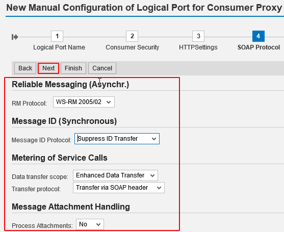
- In the SOAP Protocol tab, enter the corresponding information.
- Select Next.
Figure 15: Logical Port Data
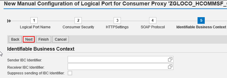
- Select Next.
Figure 16: Identifiable Business Context
Note: All the operations will display from the Service and check the SOAP Action check box method under Transport Binding for each operation/ as shown below.
- The Logical Port is successfully created.
- Select Finish.
Figure 17: New Logical Port Created
Create Binding For Service Providers
- Enter the T-Code SOAMANAGER.
- Select the Web Service Configuration hyperlink.
- Search and select the created service (/A42Q/SAP_42Q_INTERFACE).
Figure 18: Searching a Web Service
- Select Create Service.
Figure 19: Define Services and Bindings Form
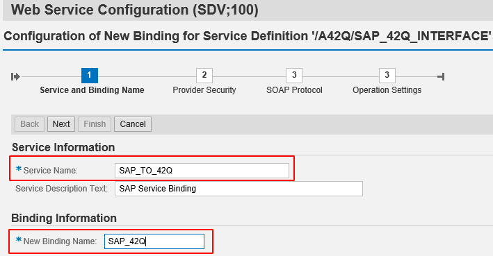
- Enter the Service Name.
- Enter the New Binding Name.
Figure 20: Service and Binding Name Section
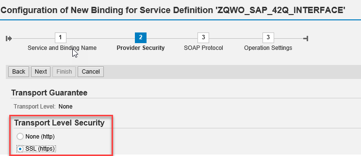
- Select SLL (https) as the Transport Level Security.
Figure 21: Provider Security Section
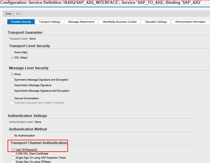
- Select User ID/Password as the Transport Channel Authentication.
- Select User ID/Password.
Figure 22: Transport Channel Authentication
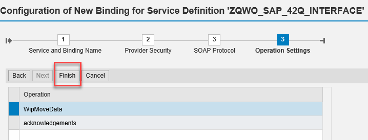
- Select Next and ignore the remaining steps.
- Select Finish.
Figure 23: Operation Settings Section
Figure 24: Service/Binding List
Retry Mechanism and Scheduling Background Jobs
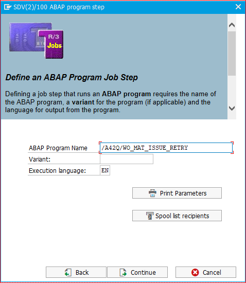
For the retry mechanism: /A42Q/WO_MAT_ISSUE_RETRY, a background job has to be scheduled for running the retry every 5 minutes. To do so, follow the steps below:
- Enter the transaction code: SM36.
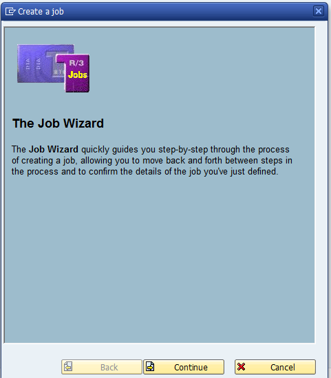
- Click on the Job Wizard button. A pop-up window will appear.
- Select Continue.
Note: The Job Name is the Retry Mechanism program name.
Figure 25: Job Wizard Window
- Select the Continue button.
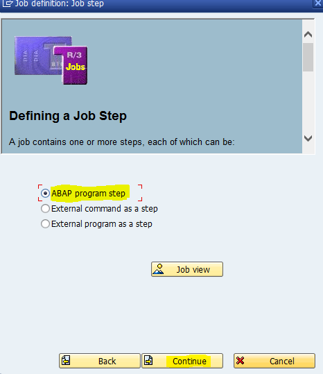
- Select ABAP program step.
Figure 26: Defining a Job Step
- Select Continue.
Figure 27: Defining an ABAP Program Job Step
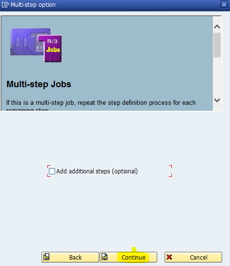
- Select Continue, again.
Figure 28: Defining Multi-step Jobs
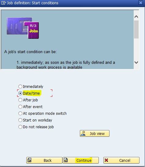
- Select the Date/time option.
- Select Continue.
Figure 29: Defining Job’s Start Conditions
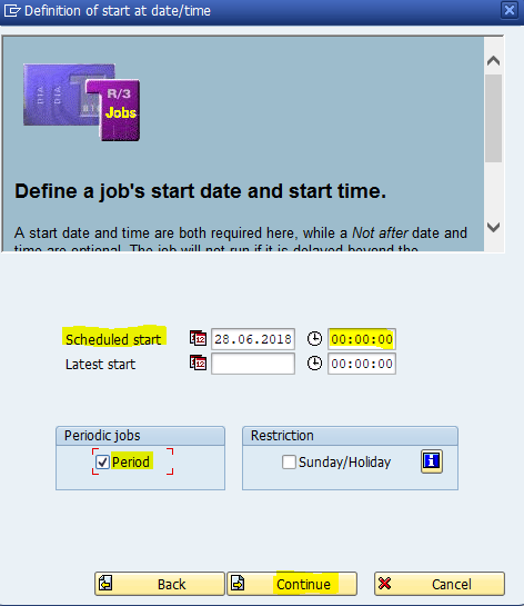
- Users can schedule the start date and time along with checking the Periodic jobs checkbox.
Figure 30: Defining A Job’s Start Date And Time
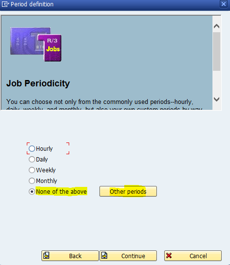
- Select one of the Job’s periodicity options or select None of the above, and then click the ‘Other periods’ button to manually input the period.
Figure 31: Defining A Job’s Periodicity
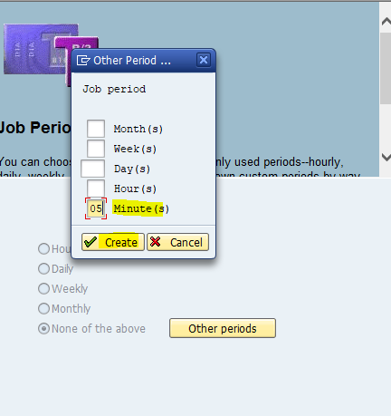
- Enter the corresponding value for any of the job periods, e.g. 05 Minute(s).
- Select Create.
Figure 32: Defining Other Periods
- After scheduling the periods, select Continue. The required background job will be successfully created.
- To test/check the scheduled background jobs, enter the transaction code: SM37.
- Repeat the same above process for scheduling the background job of remaining retry mechanisms, that is:
- /A42Q/WO_SHIPMENT_RETRY
- /A42Q/WO_UPDATE_RETRY
- /A42Q/WO_WIP_PROCESS_RETRY
- /A42Q/WO_PROCESS_ERROR_RECORD
- /A42Q/WO_AUTO_TECO
Maintain /A42Q/LOOKUP
Once the package is installed the plant needs to map the required lookup for handling hands-on time and attributes. Users should use the T-Code /A42Q/Lookup and enter the required entries.
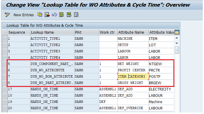
- Custom attributes: When mapped sends additional work order based data from the SAP to 42Q as additional attributes in the XML.
- If the attributes are mapped the program will pick up the Attribute value and search for the field in the respective tables.
- Levels of attributes:
- WO_ATTRIBUTE
- WO_PART_ATTRIBUTE
- WO_BOM_ATTRIBUTE
- COMPONENT_PART_ATTRIBUTE
- WO_ATTRIBUTE and WO_PART_ATTRIBUTE will be part of WO header XML. WO_BOM_ATTRIBUTE and COMPONENT_PART_ATTRIBUTE will be part of WO components XML structure.
- Map the following:
- Sequence: Auto generated.
- Lookup Name: Type of lookup prefixed with ‘DYN’.
- Plant: Name of plant.
- Attribute Name: configurable attribute name as required.
- Attribute Value: Field name/id.
Figure 33: Lookup Table Overview
- Hands on time: When mapped posts the obtained resource time against standard activity.
- SAP adapter will send resource standard values/usage rates to 42Q only when mapped in the zqwo_lookup table.
- Hands-on time received from 42Q wip moves are posted against standard activity types only for resources mapped along with corresponding work centers in the /A42Q/lookup table.
- Labor hours sent from 42Q are also handled when mapped.
- Map the following:
- Lookup Name: HANDS_ON_TIME and LABOR_TIME.
- Plnt: Plant name.
- Work ctr: name of work center.
- Attribute Value: Name of Activity.
Figure 34: Lookup Labor Time
Figure 35: Lookup Activity Types
Material Setup
For the materials for which the orders will be sent to 42Q, follow the steps below:
- Navigate to: CS02 > Header.
- Select the SAP-42Q Interface tab.
- Enter the SFDC System as MES.
- Enter the Interface Type as SYS-BUILD.
Figure 36: Header Overview
Enhancements Implementation
After the jobs are scheduled the user needs to implement the custom enhancements which can be done in two methods:
- Importing a TR for enhancements.
- Manually implementing (Enhancement Assignment).
Roles And Authorizations
Roles can be imported using a separate TR or the system administrator can give users specific access to their existing roles for the 42Q-SAP adapter custom Transaction Codes.
Assign Number Range For /A42Q/SANM Object
Create a Number Range Object using the Transaction Code: SNRO. Enter the details as per the image below:
Figure 37: Creating a Number Range Object
For generating the transaction ID, the adapter needs a number range assigned to the A42Q/SANM object. This can be assigned using the Transaction Code: SNRO.
Setup /A42Q/CONSTANT For Each Plant
Once the package is installed, the plant needs to be configured for using the SAP 42Q ERP adapter, to do so, follow the steps below:
- Enter the T-Code: /A42Q/CONSTANT.
- Enter the new entries for the plant.
- Enter the Start and End dates.
- Enter the Organization ID, Customer Code, and Project Code provided by the 42Q Team.
- Assign the number range for the /A42Q/SANM object to generate the transaction IDs.
- Enter the common Storage Location for putting away and material consumption.
- Assign the background jobs for WIP Move and Material Issue.
- Enter the Logical Port Name created for the adapter.
- Enter other configuration setups such as sending scheduled dates, enabling the ATO process, performing GR, etc.
- Enter the Retry Counter Limit for each plant based on the interval between the scheduled retry jobs.
Figure 38: 42Q Constant Values
Enhancement Assignment
Overview to 42Q-SAP Interface:
This document describes the steps to follow once the 42Q-ERP adapter add-on is installed.
Pre-requisites:
- Installation of 42Q-SAP adapter Add-on.
Required SAP Platforms, Systems, and Enhancement Packages:
The SAP system Component (SAP_BASIS) version must be 750 SP1 or higher.
Required SAP Modules:
- SAP BASIS
- SAP ABAP
- SAP Production Planning (PP)
- SAP Sales & Distribution (SD)
Required Roles:
BASIS admin roles are required for installing the adapter settings.
Add SAP-42Q Interface Custom Fields
Add Production Order Custom Fields
Before Creating Exits, add the custom fields in the CI_AUFK structure, to do so, follow the steps below:
- Enter the transaction code: SE11.
- Open the structure CAUFVD.
- Double-click on CI_AUFK, and create.
- Enter a short description.
- Fill-in the highlighted fields only.
Figure 39: Components Tab
- Save and Activate.
Add BOM Custom Fields
Before Creating Exits, add the custom fields in the CI_STKO structure, to do so, follow the steps below:
- Enter the transaction code: SE11.
- Open the structure: CSCI_STKO.
- Check if the fields shown in the image below are added or not.
- If the fields are not available, add them as shown in the image below.
Figure 40: BOM Custom Fields
Add The Enhancements
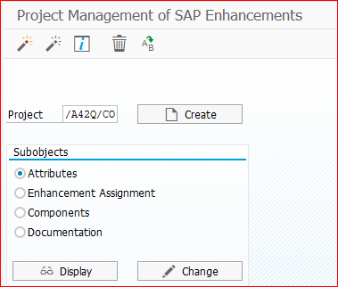
Enhancement: /A42Q/CO
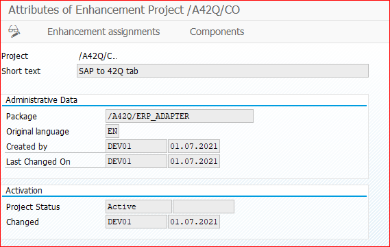
- Enter the transaction code: CMOD to create a custom tab (to process the work order from SAP-MES) for the standard transaction code: CO01.
- Enter the next project name: /A42Q/CO.
- Select Create.
Figure 42: New Created Project
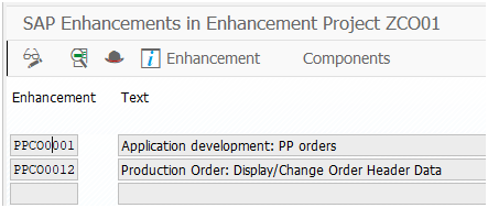
- Select the Enhancement assignments section.
- Enter the next two enhancements: PPCO0001 and PPCO0012.
- Select the Save icon.

- Select the Activate icon to activate the project.

- Click on the Components section.
Figure 43: Enhancement assignments Tab
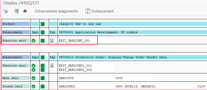
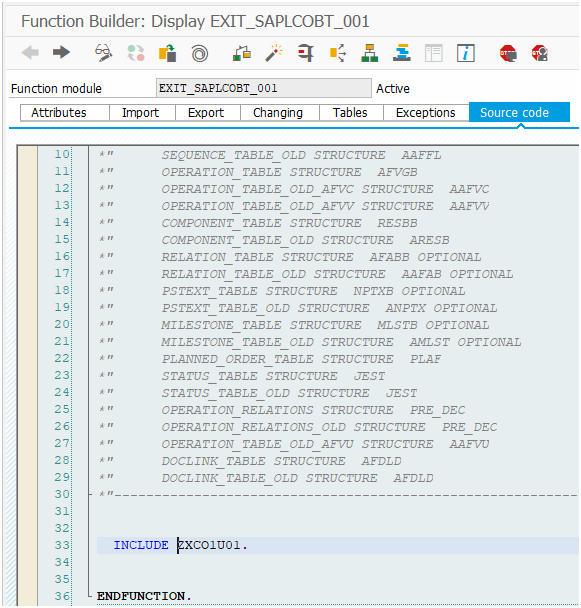
- Double-click on the function exit: EXIT_SAPLCOBT_001. It will redirect users to the Source code tab.
Figure 44: Function Exit (EXIT_SAPLCOBT_001)
Figure 45: Source Code
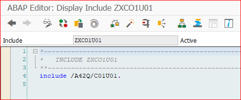
- Double-click on ZXCO1U01 ., and after the warning message appears, select Enter to comment out that line.
- Add the next line: INCLUDE /A42Q/C01U01.
- Select the Activate icon to activate the include.
Figure 46: Adding The New Include (/A42Q/C01U01.)
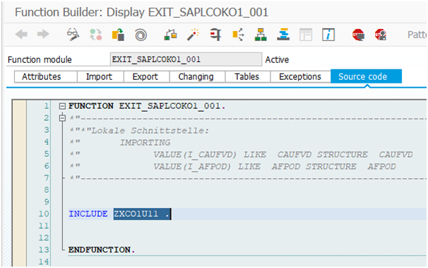
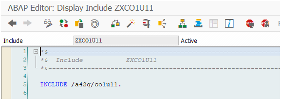
- Similarly implement the function exit: EXIT_SAPLCOKO1_001 in the Components tab by repeating steps 7 to 12, but this time commenting out: ZXCO1U11 ., adding the line: INCLUDE /a42q/co1u11., and then activating it.
Figure 47: Commenting Out The Line (INLCUDE ZXCO1U11 .)
Figure 48: Adding The New Include (/a42q/co1u11.)
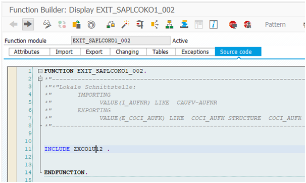
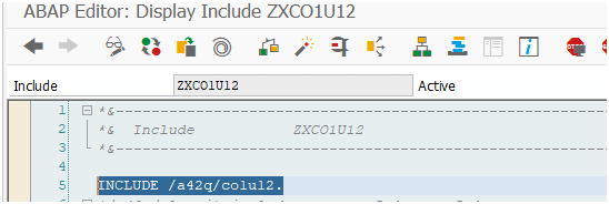
- Similarly implement the function exit: EXIT_SAPLCOKO1_002 in the Components tab by repeating steps 7 to 12, but this time commenting out: ZXCO1U12 ., adding the line: INCLUDE /a42q/co1u12., and then activating it.
Figure 49: Commenting Out The Line (INCLUDE ZXCO1U12 .)
Figure 50: Adding The New Include (/a42q/co1u12.)
- Implement the menu exit: SAPLCOCU by navigating to the Components section.
- Double-click on the menu exit: SAPLCOCU.
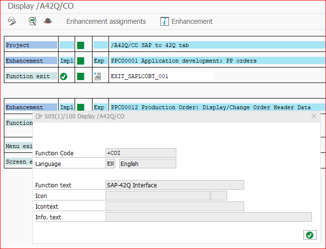
- Add the next function text: SAP-42Q Interface.
Figure 51: Adding The Function Text
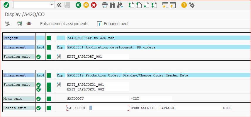
- Implement the next screen exit: SAPLCOKO1 by navigating to the Components section.
- Double-click on the menu exit: SAPLCOKO1.
Figure 52: Screen Exit
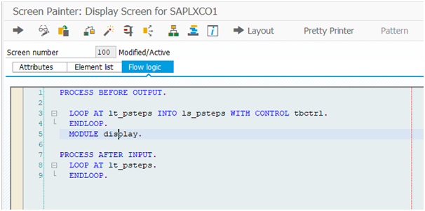
- Select the Flow logic tab.
- Add the code below.
PROCESS BEFORE OUTPUT.
LOOP AT lt_psteps INTO ls_psteps WITH CONTROL tbctrl.
ENDLOOP.
MODULE display.
PROCESS AFTER INPUT.
LOOP AT lt_psteps.
ENDLOOP.
Figure 53: Flow logic Tab
- Double-click on: Module display to expand the text.
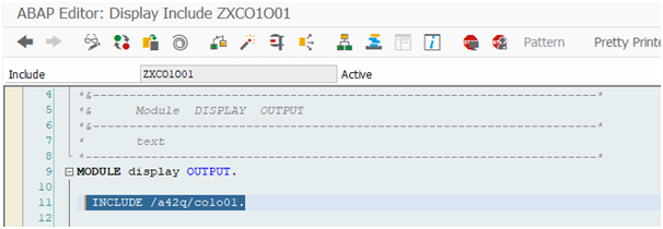
- Add the line: INCLUDE /a42q/co1o01.
- Select the Activate icon.
Figure 54: Adding The New Include (/a42q/co1o01.)
- Go back to design Layout.
- Select the Layout tab.
- Select the Utilities tab.
- Select upload.
- Navigate to: Upload/Download from the Utilities menu tab.
- Select Upload.
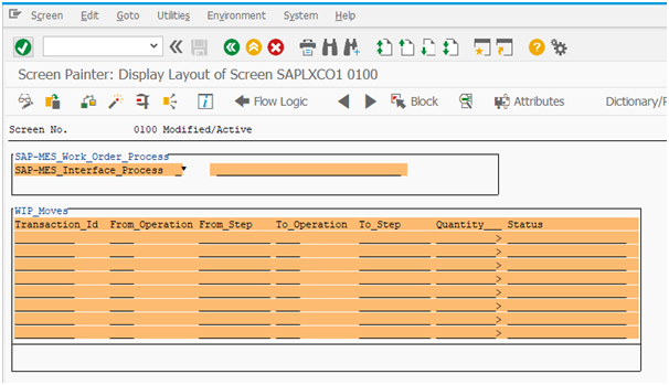
- Upload the screen design file: screen 0100 provided by 42Q team.
Figure 55: Uploaded File
- Activate the screen 0100.
- Go back to the project and activate the project.
Enhancement: /A42Q/CH
- Enter the transaction code: CMOD.
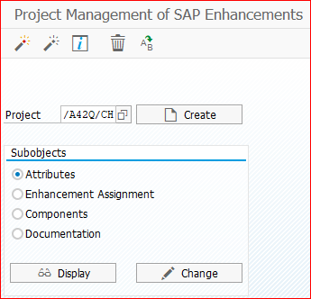
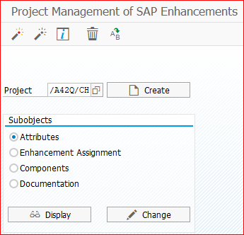
- Create a project with the name: /A42Q/CH
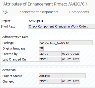
Figure 56: Creating The Project
Figure 57: Project Created
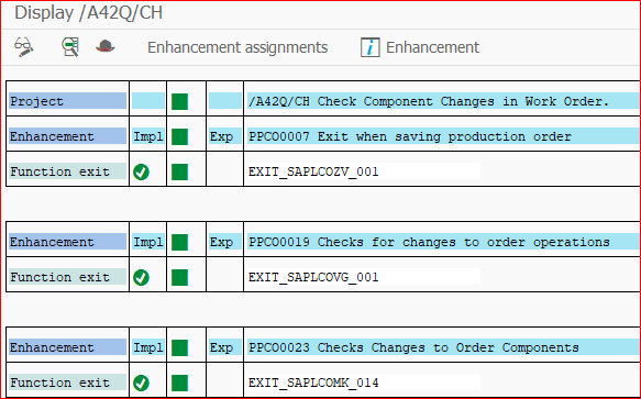
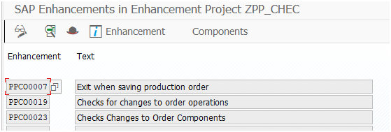
- In the Enhancement Assignment section, enter the next enhancement names: PPCO0007, PPCO0019 and PPCO0023.
Figure 58: Entering Enhancement Names
- Save and activate the project.
- Click on the Components section.
- Double-click on the Screen Exit.
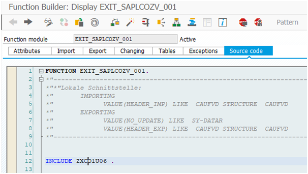
- Double-click on the screen exit: EXIT_SAPLCOZV_001. It will redirect users to the Source code tab.
Figure 59: Screen Exit (EXIT_SAPLCOZV_001)
- Double-click on: INCLUDE ZXCO1U06., and after the warning message appears, select Enter to comment out that line.
Figure 60: Source Code Tab
- Add the next line: INCLUDE /a42q/co1u06 .
- Activate the include.
Figure 61: Adding The New Include (/a42q/co1u06 .)
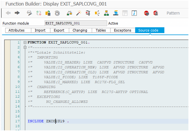
- Double-click on function exit: EXIT_SAPLCOVG_001. It will redirect users to the Source code tab.
- Double-click on: ZXCO1U19 ., and after the warning message appears, select Enter to comment out that line.
Figure 62: Source code Tab
- Add the next line: INCLUDE /A42Q/CO1U19.
- Activate the include.
Figure 63: Adding The New Include (/A42Q/CO1U19.)
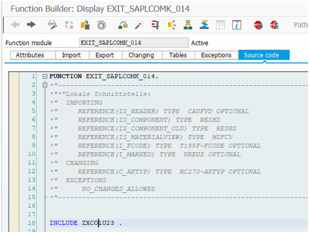
- Double-click on function exit: EXIT_SAPLCOMK_014. It will redirect users to the Source code tab.
- Double-click on: INLCUDE ZXCO1U23 ., and after the warning message appears, select Enter to comment out that line.
- Add the next line: INCLUDE /A42Q/CO1U23.
- Activate the include.
Figure 64: Source Code (INLCUDE ZXCO1U23 .)
Figure 65: Adding The New Include (/A42Q/CO1U23.)
- Go back to the project and activate the project.
Figure 66: Activating The Project
Enhancement: /A42Q/CS
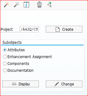
- Enter the transaction code: CMOD to create a custom tab (to process the work order from SAP-MES) in the standard T-code: CS01.
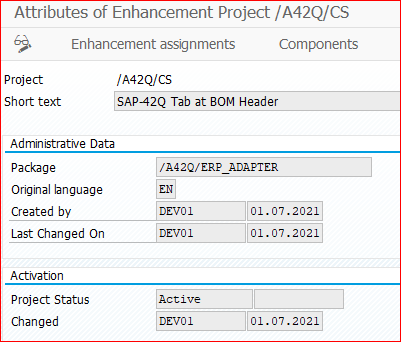
- Create a project with the name /A42Q/CS.
Figure 67: Project Creation
Figure 68: New Project
- Select the Enhancement assignments section.
- Enter the next enhancement: PCSD0003.
- Save and activate the project.
- Click on the Components section.
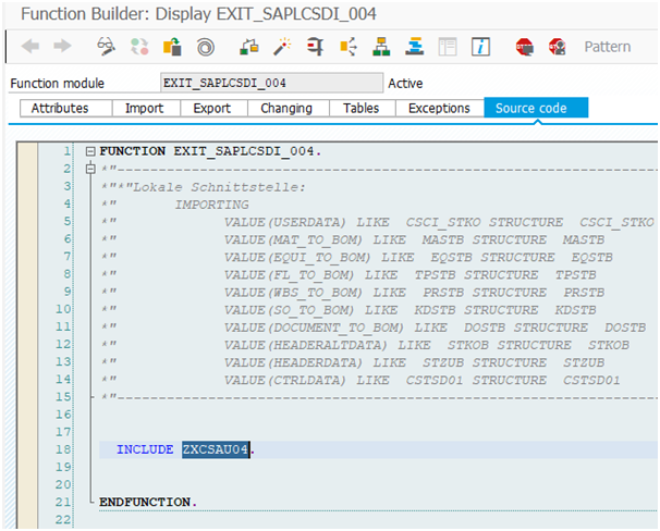
- Double-click on the function exit: EXIT_SAPLCSDI_004. It will redirect users to the Source code tab.
- Double-click on: ZXCSAU04, and after the warning message appears, select Enter to comment out that line.
- Add the next line: INCLUDE /a42q/csau04.
- Activate the include.
Figure 69: Source Code (ZXCSAU04)
Figure 70: Adding The New Include (/a42q/csau04.)
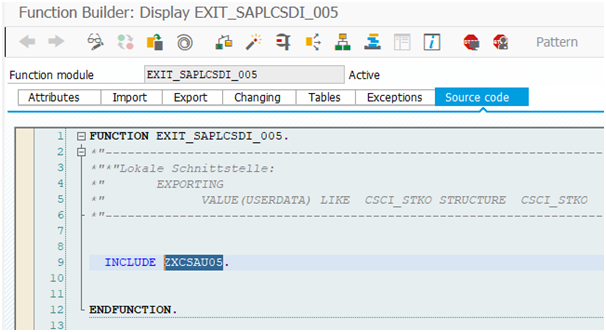
- Similarly implement the function exit: EXIT_SAPLCOKO1_001 in the Components tab by repeating steps 6 to 10, but this time commenting out: ZXCSAU05 ., adding the line: INCLUDE /a42q/csau05., and then activating it.
Figure 71: Source Code (ZXCSAU05 .)
Figure 72: Adding The New Include (INCLUDE /a42q/csau05.)
- Implement the next menu exit: SAPLCSDI by navigating to the Components section.
- Double-click on the menu exit: SAPLCSDI.
- Add the next function text: SAP-42Q Interface.
Figure 73: Menu Exit Pop-up Window
- Select Enter.
- Implement the next screen exit: SAPLCSDI by navigating to the Components section.
- Double-click on the menu exit: SAPLCSDI.
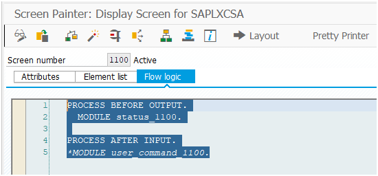
- Select the Flow logic tab.
- Add the code below.
PROCESS BEFORE OUTPUT.
MODULE status_1100.
PROCESS AFTER INPUT.
*MODULE user_command_1100.
Figure 74: Adding The Code Into The Flow logic Tab
- Double-click on: Module_status_1100.
- Add the next line: INCLUDE /A42Q/CSAO01.
- Activate the include.
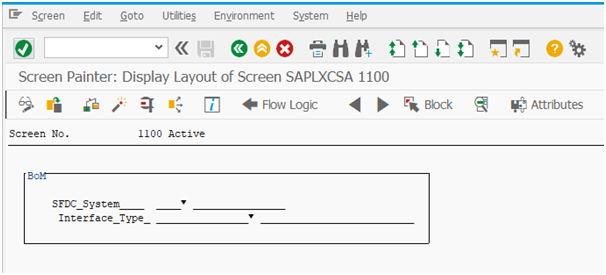
- Go back to design Layout.
- Select the Layout tab.
Figure 75: Layout Tab
- Navigate to: Upload/Download from the Utilities menu tab.
- Select Upload to upload the screen design file 1100 provided by 42Q team.
- Activate the screen 1100.
- Go back to the project and activate the project.
Enhancement: /A42Q/VL
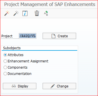
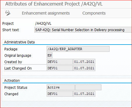
- Create a project with the name /A42Q/VL for Serial Number Selection in Delivery processing.
Figure 76: Project Creation Form
Figure 77: New Project Created
- In the Enhancement Assignment section, enter the next enhancement name: IQSM0001.
Figure 78: Entering An Enhancement Name
- Select the Components tab.
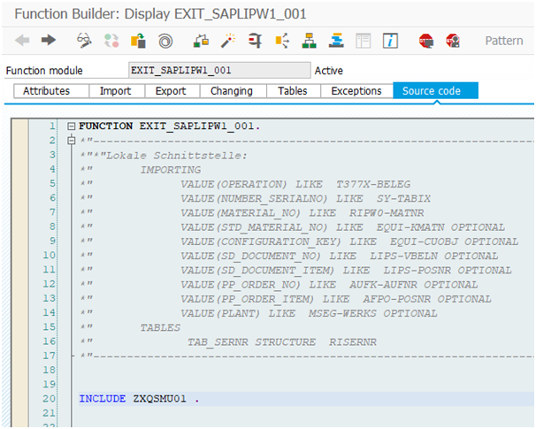
- Double-click on the function exit: EXIT_SAPLIPW1_001. It will redirect users to the Source code tab.
Figure 79: Function Exit (EXIT_SAPLIPW1_001)
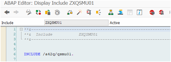
- Double-click on: ZXQSMU01., and after the warning message appears, select Enter to comment out that line.
- Add the next line: INCLUDE /A42Q/QSMU01.
- Activate the include.
Figure 80: Source Code (ZXQSMU01.)
Figure 81: Adding The New Include (/A42Q/QSMU01.)
- Go back to the project and activate the project.

