42Q-MES0145-C Production Workbench
42Q Home > Conduit > Production Workbench
Contents
- 1 Introduction
- 2 Pre-Configurations
- 3 Production Workbench
- 3.1 Configuration
- 3.1.1 User Role Configuration
- 3.1.2 Configuration Panel
- 3.1.3 Display Distribution
- 3.1.4 Color Selection
- 3.1.5 Automatic Submit Checkbox
- 3.1.6 Multi-Level Center
- 3.1.7 Smart Commit Checkbox
- 3.1.8 Repeat Transaction
- 3.1.9 Menu Bar
- 3.1.10 Shop Order Sequence panel
- 3.1.11 Unit Scanning
- 3.1.12 Repair Knowledge
- 3.1.13 Quick Actions
- 3.2 Shop Order Prioritization
- 3.3 Command In Unit
- 3.4 Conduit PTS Rework
- 3.5 Building the Transaction
- 3.6 Containerization
- 3.6.1 MLC Config: Creating a new Container Configuration
- 3.6.2 Create a New Container
- 3.6.3 PW - Add Non-Serialized Units
- 3.6.4 PW - Add Serialized Units
- 3.6.5 PW - Remove Serialized Units
- 3.6.6 PW - Remove All Serial Numbers from Container
- 3.6.7 PW - Remove Non-Serialized Units
- 3.6.8 PW - Pagination
- 3.6.9 PW - Filter by a Specific Element
- 3.6.10 PW - Close/Autoclose Container
- 3.6.11 PW - Refresh Upon Autoclose Container
- 3.6.12 Packing Control
- 3.7 QCP Checklist
- 3.8 Multimedia Files
- 3.9 File Upload
- 3.10 Take Photos
- 3.11 Advanced Configuration
- 3.12 Shop Order Sequencing
- 3.13 Shop Order Release Notes
- 3.1 Configuration
- 4 Labor Tracking
- 5 Decoration Of The Items From The Shop Order And The BOM List
- 6 Show Location
- 7 Multi Scanning
Introduction
Production Workbench is a powerful, responsive, and cross-platform tool designed to streamline data capture on the shop floor. It offers a wide range of customizable options to meet individual needs,
including enhanced work instructions and the ability to handle deviations effectively. With Production Workbench, users can easily capture data in multiple ways while maintaining tracked and non-tracked assembly components.
Additionally, it provides the flexibility to view, add, remove, and map attributes to multiple documents, and even single chapters, all from a single user interface at the same station. The tool also offers convenient features for recording and repairing defects.
These capabilities are made possible through seamless integration with the Shop Floor Control Conduit connection.
Production Workbench leverages a variety of Conduit commands, empowering users to view a unit's history and effectively manage Attribute Value Pairing (AVP) to define and configure steps.
Conduit itself is an advanced 42Q data collector that supports requests for multiple Client IDs without the need for dedicated servers for each client. Conduit ensures improved data consistency and network performance.
This is achieved by optimizing message transmission, reducing latency, and maximizing bandwidth utilization through larger messages.
Furthermore, Conduit eliminates duplicate work by removing the reliance on local databases and incorporates high-performance native code to enhance throughput.
Key Features
- Document Display Customization
The document display feature allows clients to configure the presentation of documents based on process requirements and attributes.
- Seamless Transactions with Conduit
Operators can perform various actions such as executing commands and adding or removing attributes and components, all within a single transaction handled by Conduit. This ensures efficient and reliable operations.
- Intuitive Scanning Interface
The scanning interface offers multiple views and provides a user-friendly experience for operators.
- Portal Integration for Cross-Platform Support
The tool seamlessly works on any device with a browser, enabling cross-platform compatibility and flexibility.
- User-Friendly Instructions
Documents can be mapped to display relevant work instructions when a unit is scanned, providing operators with clear and helpful guidance.
- Agile Document Control System Integration
Production Workbench integrates with the Agile document control system under ECO (Engineering Change Order) with the top-level agile part number. This streamlines document management and ensures accurate information retrieval.
- AVP Support
The tool supports Attribute Value Pairing (AVP), allowing the mapping of questions, checkboxes, and other elements along with work instructions.
Note: Before using Production Workbench, it is important to perform Shop Floor Control, Document Mapping, and Server configurations specific to each client.
These configurations are necessary to ensure that the Production Workbench accurately displays manufacturing prompts and online work instructions tailored to individual needs.
Pre-Configurations
Shop Floor Control Configuration
To ensure the proper display on Production Workbench, it is necessary to configure certain parameters in the Shop Floor Data Collection system. The following steps outline the process:
To access Shop Floor Configuration navigate to: Shop Floor Control > Configuration > Shop Floor Configuration
Locate the settings to configure: Shop Floor ID, Location, Part Number, and Product Route:
- Define the appropriate values for each parameter based on your specific requirements.
- Ensure that the Shop Floor ID uniquely identifies the shop floor or production area.
- Specify the Part Number associated with the manufacturing process.
- Define the Location to accurately track the physical position of the production.
Defining Attributes and Assemblies: If desired, configure any additional attributes or assemblies related to the production process. This step allows you to tailor the Production Workbench to your specific needs and capture relevant data.
Note: Production Workbench and Conduit utilize the standard SFDC Configuration. Please refer to the Shop Floor Configuration documentation for more information.
Figure 1: Shop Floor Control Configuration
Work Instructions
Work Instructions allow users to maintain documentation by uploading documents via Agile local networks, or URLs.
These instructions aim to outline the steps to assign appropriate documentation to the end-user regarding a process or part for which they require work instructions or deviation information.
Navigate to Administration > Document Control > Work Instructions
For more information please visit: Work Instructions
Profile Maintenance
In the Profile Maintenance portlet users can create a profile and define the permissions. The purpose of this functionality is to assign users with this profile in order to allow or prevent users from changing the configuration of Production Workbench.
The profile can be created by navigating to: Administration > Profile Maintenance.
With this configuration, it is possible to prevent the users such as Operators that are working in a Location in Production Workbench from making basic changes to the configuration, unless their Supervisor authorizes it.
However, for the rest of the configuration, users (operators) do not need the Supervisor’s authorization.
Assign User
To assign users with a profile, follow the step list below:
Select the checkbox of the profile.
- Select Assign User.
Figure 2: Assign User Button
Figure 3: Assigning Users
- Select Back to return to the previous page and define permissions
Figure 4: Define Permissions Button
Define Permissions
To define permissions for the users assigned to this profile, follow the step list below:
Select the checkbox of the profile.
- Select Define Permissions.
- Check or Uncheck the boxes to grant or deny the corresponding permissions.
- Select Save to save all changes or Back to abort.
Configurations that are able to be changed by the assigned users are highlighted in green color.
These configurations do not require the supervisor's authorization to be changed; for the rest of the configurations, the supervisor's or any other user with administrator privileges authorization (credentials) will be needed.
Production Workbench
Production Workbench is a 42Q scanning interface that allows mapped Work Instructions to display alongside the scanned unit.
The interface captures data, displays enhanced work instructions and/or deviations, maintains tracked and non-tracked assembly components, removes attributes, and records/repairs defect codes according to the configuration.
Production Workbench also allows users to use a library of Conduit commands.
Configuration
The Production Workbench client can be accessed only inside the Portal from Production > Production Workbench.
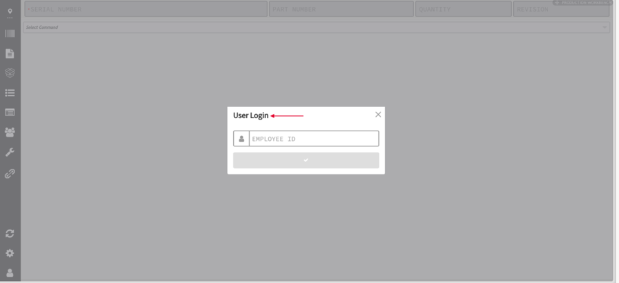
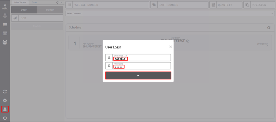
To access the Production Workbench the user needs to enter a valid employee number. The Project, Plant Code, and Portal info are pulled as the user is already logged in. In addition, data sharing from the Portal to Production Workbench is enabled.
Enter the employee number, then click on the Submit button denoted by a checkmark. See below the User Login.
Figure 5: User Login
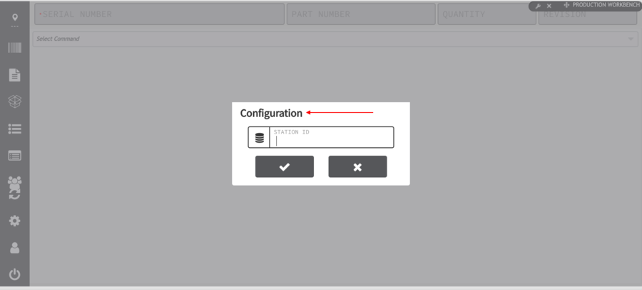
Next the configuration window will appear, requesting a valid Station ID, click on submit or cancel to continue, this information can be later configured from the menu.
Figure 6: Configuration
User Role Configuration
In order to be able to save the configuration at the Production Workbench, two conditions must be met:
- The first condition is the employee who saves the configuration must have a Supervisor employee type assigned, this can be done at Quality > Employee Validation Maintenance > Employee Maintenance.
Note: Even if the user’s employee type is set as Supervisor, if the processes on the route are EV controlled, the Operator must be certified to scan at the processes on the route. For more information on setting up Employee Validation
see Employee Validation Maintenance & Employee Validation Configuration.
- The second condition is that the generic attribute: ps_configuration_supervisory is active. The values should be yes/true/no/false. Attributes activation is performed at Administration > Generic Attribute Maintenance.
Note: If the user is not set as a supervisor at Employee Validation Maintenance, an error message is displayed after the submit button denoted by a checkmark is selected on the main Production Workbench page.
1. Enter the Employee # and Password.
The Configuration page is displayed after the user login as Supervisor, previously configured at the Employee Configuration Portlet.
Users can turn on or turn off the Employee Validation login in Production Workbench by setting theps_user_login_disabled Generic Attribute.
Note: If the ps_user_login_disabled Generic Attribute Value is set as FALSE, the user icon will appear and the pop-up for employee authentication will be displayed. If the Generic Attribute is set as TRUE, the user icon will be hidden.
For more information please refer to the Generic Attribute Maintenance.
Configuration Panel
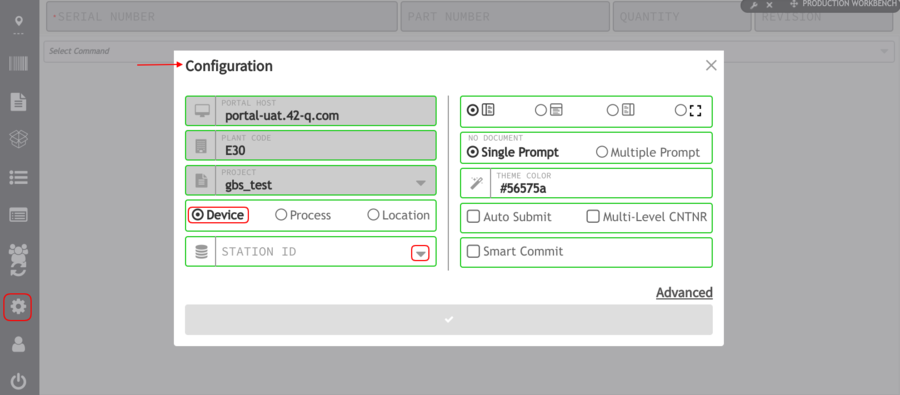
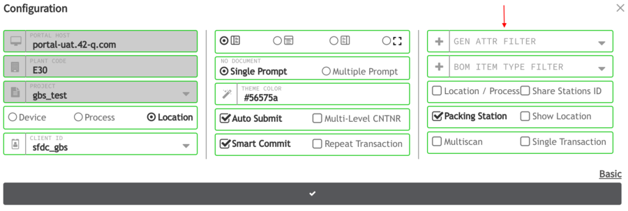
The configuration panel is located on the left side of the screen on the vertical menu, here users can select the configuration form Device, Process, or Location. Users can select a Site and Station ID in the configuration panel.
Figure 7: Configuration - Device/ Station ID
Once Station ID is selected, users will be able to use the device drop-down in the vertical menu to view the device.
Note: Configurations that are able to be changed by the assigned users are highlighted in green color.
These configurations do not require the supervisor's authorization to be changed; for the rest of the configurations, the supervisor's or any other user with administrator privileges authorization (credentials) will be needed.
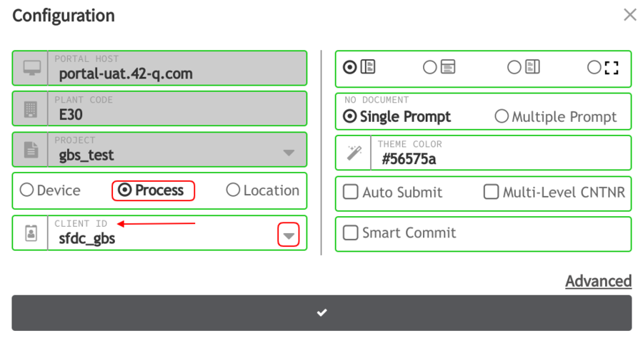
Figure 8: Configuration - Process / Client ID
AVPGROUP1
- Portal Host - Portal host is the DNS entry or IP of the portal. e.x.: 42qportal.42-q.com
- Plant Code - ID of the Plant created in Administration > Site Maintenance.
- Project - Name of the Portal Site.
- Data Collector - Select how the data collectors should be listed by selecting the radio button: Devices, Process, or Location.
If the users select either Process or Location the window would remain the same and the user needs to inform the Client ID (to select the base if there are more than 1 project in one base).
It is not mandatory to fill it; however, if the Device is selected, Station ID field is displayed and it is mandatory to be filled. Station ID is tied to the scanning locations and is found in Administration > SFDC Administrator > Device Maintenance.
Note: When accessed from within the portal, the Portal Host, Plant Code, and Project are automatically populated and cannot be modified.
To access advanced configurations, select Advanced, located at the bottom right of the panel.
- Share Stations ID - This option allows users to view the Devices contained in one or more Shop Floor ID that belong to a Station ID with a unique name.
Note: In order to use the Share Stations ID functionality, Production Workbench must be configured by Device and also select a Station ID. These actions will not need a supervisor's authorization.
Figure 9: Share Stations ID Checkbox
Note: The default limit of devices that can be displayed in Production Workbench when using the Share Stations ID functionality is 10000.
Display Distribution
Screen distribution - This can be orientated to either the Left, the Center, or the Right by selecting the radio button next to the icon.
Single/Multiple prompts
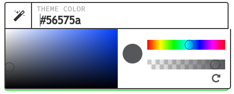
Color Selection
Figure 10: Color Picker
Automatic Submit Checkbox
Enable Automatic Submit to have the system automatically send the data when a terminator is added.
Figure 11: Auto Submit
Multi-Level Center
Enable Multi-Level Center to allow the option to create a pallet scanning a container. If the checkbox is enabled, users can scan a container or serial number and it will be displayed within the windows to select.
If the Multi-Level container is unchecked, the container will take the previous configuration saved in the local storage.
Figure 12: Multi-Level Center
Smart Commit Checkbox
Enable Smart Commit If the user selects the smart commit checkbox, and presses Enter, the submit is automatically executed.
Figure 13: Smart Commit Checkbox
Once all configuration has been completed, select the Submit button denoted by the checkmark to save the configuration.
Repeat Transaction
This option allows the user to enable the bulk transaction functionality.
Figure 14: Repeat Transaction

To access advanced configurations, select Advanced, this will show another row on the configuration menu.
Figure 15: Advance Configuration
Users can add different filters and options, such as the Share Stations ID option.
This allows users to view the Devices contained in one or more Shop Floor ID that belongs to a Station ID with a unique name, or the Packing Station, Show Location, Multiscan or Single Transaction.
Note: In order to use the Share Stations ID functionality, Production Workbench must be configured by Device and also select a Station ID. These actions will not need a supervisor's authorization.
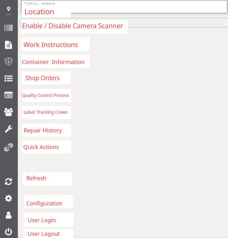
Menu Bar
Figure 16: Menu Bar
This bar appears on the left side of the screen. Some icons appear by default and some others under certain configurations or requisites:
- Location: This allows the user to select the required location (Default functionality).
- Enable/Disable Camera Scanner: This option allows enabling or disabling the camera scanner (Default functionality).
- Work Instructions: This icon helps to search and display a work instruction related to a shop order, a part number or a serial number without scanning a unit (Default functionality).
- Container Information: Provides the Project ID, Container Level, and Part Number of a scanned container (Default functionality).
- Shop Orders: Since the main page only displays the main 5 shop orders, this list allows users to visualize all the available shop orders for the specific serial number.
This menu allows the user to see the first 50 shop orders for the selected location/process (Default functionality).
Notes:
- Shop orders arrangement depends on the priority that has been assigned to them at Shop Order Release, besides, in order for side panel shop order or “main shop orders” to be displayed, the generic attribute “shop_order_scheduling” as to be set as true.
- Through the generic attribute ps_so_scheduling_panel_orders the number of shop orders that will be displayed in the order sequencing panel can be configured without limit of number. Remember that by default, 5 shop orders will be shown.
Please refer to this link for more explicit information.
Figure 17: Main Shop Orders
- Quality Control Process: Give access to a pre-configured checklist for specific Location, Process, Location by Part Number, and Location by User.
- Labor Tracking/Crews: Display the list of shop orders assigned to a location and the operators that are working on it, as well.
It provides the time that operators spend in the current operation and the available crews (It needs special configuration).
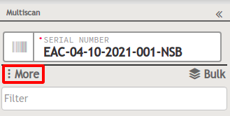
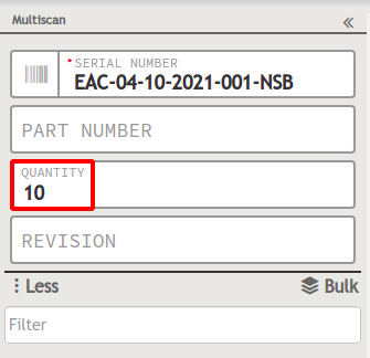
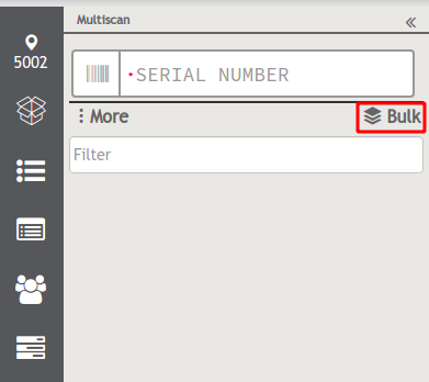
- Multiscan: Display a special field to scan a batch of serial numbers at the same time (It needs special configuration).
- Repair Defects: Display the most recent defects and repair codes for part number scanned (It needs special requirements).
- Refresh: This option clears the Serial number, Part number, Quantity, and Revision fields and returns to display the 5 main shop orders for the location (Default functionality).
- Configuration: Pops up Configuration Window (Default functionality).
Note: For detailed information about those features that are not displayed by default and require specific configuration or requirements, please refer to the Table of Contents of this document to search their corresponding section.
Shop Order Sequence panel
In order to have visibility of those work orders with running hands-on-time, users can, optionally, enable extra information fields in the Shop Order Sequence panel.
This functionality helps users to know if a work order is running, paused, or not started yet, as well as a counter of the current hands-on-time/cycle time.
The Shop Order Sequence panel displays hands-on-time information, part number extra information, and it has a visual indicator to show when a shop order of this kind started running (only for Non-Serialized-Batch).
Color code for Non-Serialized Batch serial numbers:
- Green: RUNNING
- Yellow: PAUSED (It changes to yellow when a user executes a Release Scan Activity for a serial number)
- Grey: STOPPED
To enable or disable the extra fields for the Shop Order Sequence panel:
- Navigate to Administration > Generic Attribute Maintenance.
- Set as “True” the generic attribute “ps_so_scheduling_active_extra_fields”.
To display the Shop Order Sequence panel with extra fields:
- Select the Shop Orders icon from the bar menu.
- The Shop Order Sequence panel will be displayed with the following additional information, once users have done the corresponding settings:
- Part Number Description
- Unit of Measurement (UoM)
- Linked SO (Shop Order)
- Assy Special Instructions
- Customer PO (Product Owner)
- Part Type
- Start Date
- Complete Date
- Part Number Flexfields
- Shop Order Generic Attributes
Note: The Part Number Flexfields and the Shop Order Generic Attributes configurations, allow users to customize the name of the flex fields or generic attributes that will be shown in the Shop Order Sequence panel.
Both can be applied at a site or a process level.
The site level configuration must be done at Administration > Generic Attribute Maintenance. For further information, please refer to SOP Generic Attribute Maintenance.
The process level configuration must be done at Shop Floor Configuration > Location. For further information, please refer to SOP Location Maintenance.
Figure 18: Shop Order Sequence Panel
To configure the extra information fields, please check the chart below to know where must be done:
For further information about these configurations for extra fields, please refer to SOP Part Number Maintenance and/or SOP Shop Order Control.
Unit Scanning
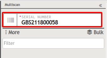
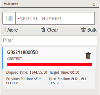
The scanning functionality, featured in Production Workbench, allows users to scan serial numbers by writing them in the corresponding field, located at the top bar of the screen.
When users scan a unit, the system displays its part number, quantity, and revision information.
Figure 19: Serial Number Field
There are two types of serial numbers that can be scanned:
- Serialized Units: Refers to unit serial numbers of tracked components within a batch.
- Non-Serialized Batch: Refers to shop orders that work by batch
The system allows users to enter the desired quantity in the corresponding field. Also, the system has different responses according to different actions:
- The system will automatically clear the quantity field if:
- Users modify the Non-Serialized Batch in the serial number field
- Users quit the Non-Serialized Batch in the serial number field
- The system will automatically create a new Non-Serialized Batch if:
- Users input a work order that was already split
Note: This configuration only affects the Non-Serialized Batch.
Repair Knowledge
This functionality displays the most frequent and useful repair decisions symptoms, defect codes, and repair codes used by the repair technician. The system has the capability to store each technician's decision, building a knowledge database.
The principal purpose of this feature is to reduce the repair time.
In order to display the Repair Defects icon, users must define permissions to an existing profile in the Profile Maintenance portlet, so that this feature is available for a site, with the following path:
Production > Production Workbench > Production Workbench > Repair Knowledge > Repair Knowledge Panel.
For further information, please refer to the Admin Profile Maintenance.
Note: The default profiles cannot be modified.
Access the Repair Knowledge information
There are two options to display the Repair Defects list:
Option 1
- Scan a unit.
- The repair knowledge list will be displayed.
Figure 20: Scan Unit to Display the Repair Defect List
Option 2
- Once the Repair Defect is open, input a Part Number in the corresponding field, then press Filter.
- The repair knowledge list will be displayed.
Figure 21: Input Part Number to Display Repair Defect List
The Repair Knowledge panel will show by default certain information that can be modified by using the available filters to do more precise searches, and/or the different options for columns, to display additional information.
To add more filters:
- Select the +More icon
- Check the box or boxes of the desired filters to be added
To add more columns:
- Select the Columns icon
- Check the box or boxes of the desired columns to be added
Note: To restore the default view for filters and columns, select the “Restore Defaults” options from the corresponding dropped-down menus.
Repair Knowledge data from Defect and Repair Codes
User can also access to more specific information from the Defect and Repair Codes. To do so, just:
- Select a Defect Code or a Repair Code.
Figure 22: Defect or Repair Code Selection
- In both cases, the system will show automatically another screen with the following information:
- Serial Number
- Date of Defect saved - linked from Default View
- Operator who recorded the Defect Code - linked from Default View
Note: The Repair Code button will be disabled if there is a defect code in a part number without a valid repaired code. To check if the Repair Code button is enable, navigate to Administration > Generic Attribute Maintenance
- If the generic attribute allow_repair_value_yes is set on value as True / Yes, the yes option in the repaired code list will be displayed in the repaired code dropdown list when scanning with a defect code-related.
If the value is set as False/ No, the yes option in the repaired code list will not be displayed in the repaired code dropdown list when scanning with a defect code.
- If the generic attribute allow_repair_value_nff is set on value as True / Yes, the nff option in the repaired code list will be displayed in the repaired code dropdown list when scanning with a defect code-related.
If the value is set as False / No, the neff option in the repaired code list will not be displayed in the repaired code dropdown list when scanning with a defect code related.
For more information about these attributes, please refer to Generic Attribute Maintenance
Once there, users can access the Unit History from this screen by selecting a desired Serial Number. This action will automatically open it in a new window.
To return to the Default View, just select the X icon, located at the top right of the panel.
Figure 23: Display Most Recent Serial Numbers by Defect Code
Figure 24: Display Most Recent Serial Numbers by Repair Code
Quick and Detail Repair Actions
The system provides two options to execute repair actions in the Production Workbench. These are available in the Frequency Table displayed below the list of the most recent defect and repair codes.
The Frequency Table can optionally be hide or display. It shows six columns with the following information:
- Defect Code
- Serial Number
- Part Number
- Reference Designator
- Suggested Repair Code drop-down list with the five most probable options that users can use to repair
- Repair Action with two options:
- Quick (automatically repair)
- Detail (the system uses the selected repair code, but ask user to enter manually extra information)
Figure 25: Frequency Table
Users can enable or disable the suggestions drop-down list and the Quick button from the Repair Action column, as well, with the generic attribute ps_machine_learning_enabled. It will be enabled with a value in TRUE.
To execute a Quick repair action:
- Select a repair code from the drop-down list suggestions.
- Then, select the Quick button.
- The system will display a message confirming the repair action.
To execute a Detail repair action:
- Select a repair code from the drop-down list suggestions.
- Then, select the Detail button.
- The system will redirect to the main screen of Production Workbench asking to enter more information.
- Once done, a message will be displayed to confirm the repair action.
Quick Actions
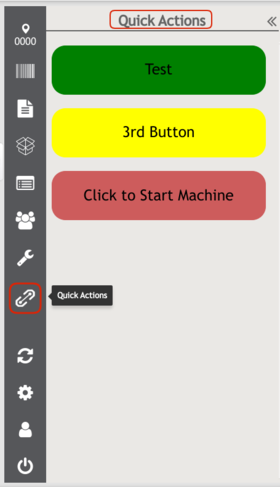
This functionality displays custom buttons that help the system to communicate with IoT devices mapped to a given manufacturing location, to produce or consume events with a simple click.
This bidirectional machine communication implemented in 42Q also allows users to:
- Have a configurable option by workstation to issue an auto-stop to the machine, when a shop order passes from the current location to the next.
- Display red warnings when:
- An SPC chart mapped to the workstation is out of control limits
- Yields & defects at the workstation are out of control limits
To display the Quick Action button, users must follow three previous configurations:
- IIoT Configuration, to configure the asset and the asset type management of the edge device (further information here)
- Quick Action Configuration, to create, custom, and configure the button(s) that will be displayed in Production Workbench (further information here)
- Event Link Configuration, to create a bidirectional channel that communicates the edge devices with the action buttons (further information here)
To display the Quick Action Panel:
- Select the corresponding icon from the bar menu.
- The Quick Actions panel is displayed with the buttons configured previously for this location.
Figure 26: Quick Actions Panel
Shop Order Prioritization
Users can configure two modes of displaying shop orders list by configuring this in the Location Form flex field:
- To see all the shop orders that are in the manufacturing line, SEQUENCED_AND_ FIFO.
- To see only one, SEQUENCED_ONLY.
Screen Elements
Reference Tabs
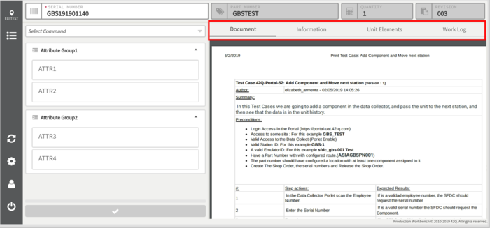
Document, Information, and Work Log tabs appear at the top of the displayed document and allow the user to visualize the additional information of the serial and part number is being processed.
Figure 27: Reference Tabs
- Document Tab - The Document tab displays documents that are mapped to the Part Number at the scanning location. If there is no mapped document, this tab will not display.
- Information Tab - The Information tab displays Employee, Unit, and Production information.
- Work Log Tab - The Work Log tab displays information about the scanned unit, specifically the executed Auto commands along with the results obtained. Added attribute and component information will be displayed in this tab as well.
Dynamic Work Instructions
The Dynamic Work Instruction functionality helps users to get the work instructions related to a shop order, a part number, or a serial number in the Production Workbench without the need to navigate to another module.
The following are its main features:
- Access to the documentation before scanning a unit.
- Open several documents at the same time, no matter if they are from a shop order, a part number, or a serial number.
- Color code to identify if the displayed work instructions belong to a part number (gray), a shop order (blue), or a serial number (green).
- Users can open documents of two different shop orders that belong to the same part number.
- Limit the documentation to the process related to a specified location.
There are two different ways to access documentation:
- By using the Dynamic Work Instructions icon located on the bar menu.
- By using the Dynamic Work Instructions shortcut icons located on the schedule panel (next to the shop order or a serial number).
Dynamic Work Instruction from the bar menu
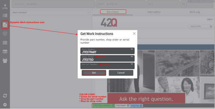
This functionality is the first option to search and display a work instruction before scanning a unit. To do so:
- Select the work instructions icon located in the left menu bar.
- Write down a part number, a shop order or a serial number to display the related work instructions to it.
- Select the Get button.
- The work instruction will be displayed in the screen, under the “Document” tab of the panel.
Figure 28: Get Work Instructions
Note: When the user configures to work in location mode, the Production Workbench will take the process that belongs to the selected location.
But when the user configures it to work in device mode, the Get Work Instructions form will ask users to write down the process.
Figure 29: Get Work Instructions - Process Field
Dynamic Work Instruction shortcuts from the Schedule panel
Users can also access the work instructions before scanning a unit by using the schedule panel shortcuts, at the shop order level or in the serial number level:
- Select the Get Shop Order icon located next to the shop order/serial number.
- The related work instructions will be displayed on the screen.
Figure 30: Get Shop Order Document Icon
Figure 31: Get Serial Number Document Icon
When users are working with Non-Serialized Batch, and the shop order has more than one unit, the system will prompt a confirmation message asking to select a serial number to display the corresponding documentation.
Note: If the Non-Serialized Batch has only one unit, the Production Workbench will take the serial number of this unit to display its mapped documentation.
Document Display
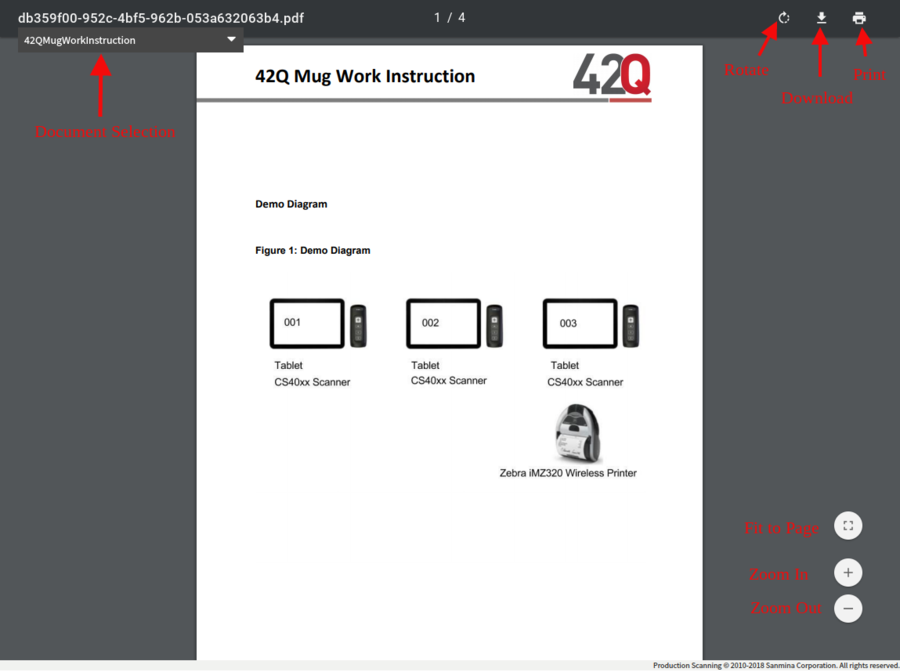
In the Document tab, users may view mapped documents alongside the prompt information. The Document display tab offers a view page display options for a better viewing experience.
Figure 32: Document Display
- Document Selection - If there is more than one document mapped to the Part Number at the current scanning location, users may select which document to display.
- Zoom Options - The document interface can be zoomed in or out or can be set to Fit Page.
- Rotate - The Rotate button allows the document to be rotated clockwise.
- Download (Local) - Selection of the Download button will allow the document to be saved to the user’s local hard drive.
- Print - Selecting Print will allow the document to be sent to a local printer.
Full-Screen View
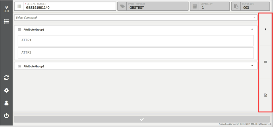
If there is no mapped document to display, the commands and prompts will stretch to take up the full screen. The Information, Unit Element, and Work Log tabs collapse into an expandable vertical menu at the right side of the screen.
Note: There is another option that is displayed only when "Single Prompt" is enabled. This option will display all the commands/prompts that are added.
Figure 33: Full-Screen View
When an icon is clicked, the tab will expand to display the details of each category.
Commands
Production Workbench utilizes the Conduit command library for use when building transactions. Multiple commands can be added as needed.
Prompts for the commands can be answered and saved in any order before ending the transaction by selecting the Submit button.
To select a command from the command list users must follow four steps:
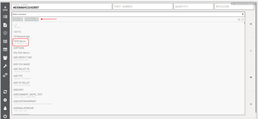
- Select the Command dropdown menu to display the list of selectable commands.
Prompts will display one at a time based on their Step configuration. Users may jump to a different step by selecting it from the Command list.
Note: The full list of Conduit Commands and existent Macros can be found in the Conduit Command Appendix; those commands can be accessed either through Command Register or through Production Workbench.
If the ps_device_hide_commands generic attribute is set to TRUE or YES, all the commands and macros will not be displayed until a unit is scanned.
- Enter the desired command into the Select Command field, or scroll the list until the desired command is found.
- Select the command to add it. Multiple commands can be added at the same time.
Figure 34: Add a Command
- After selecting the command, select the Complete Selection button to close the drop-down list and add the command values.
5. Select the Delete button to unselect the command.
Once all the desired commands have been added, select the Submit button. The added prompts will display their configured prompts.
Figure 35: Enter Command Values
Note: A terminator command (e.g. END, MOVE, Sample Unit) must be submitted to end a transaction and move the unit to the next PASS/FAIL location.
Note: The command banner that is located in the right upper corner of every command can be hidden or shown by configuring the generic attribute: ps_hide_command_titles,
if it is enabled, all the command banners will be hidden, but if the cursor hovers over a command, the banner will be displayed.
On the other hand, if it is disabled, all the command banners will be shown.
Users can clone the command selected by clicking on the Repeat Command button.
Figure 36: Repeat
And Record Media, which will allow users to upload images from the gallery or take photos.
Figure 37:Upload
Commands to replace subassemblies
Users can replace subassemblies at any level of the hierarchy by selecting the commands “Replace Tree Component” (main subassemblies) or “Replace Unit Tree Component” (subassemblies of a component) from the list of commands.
- Select a command from the list displayed.
- Write in the fields the Old Component Id, the Reference Designator (both can be taken from the Unit History of the Shop Order), and the New Component Id.
For more information please refer to the Conduit Command Appendix.
Figure 38: Replace Unit Tree Component Command
Note: The Replace Unit Tree Component command requires a valid Unit Serial Number to proceed.
Figure 39: Replace Tree Component Command
Command In Unit
The Command In Unit is a functionality that allows users to execute commands in a faster way, sending all the needed data at once.
In the next step list, users will see how to use the Command In Unit functionality:
- Enter the command structure below:
CMD://<Command Name>$<param1>$<param2>$<paramN>
Replace the data between "<>" with the next information:
<Command Name>: Name of the command to execute.
<param1>: First parameter’s value.
<param2>: Second parameter’s value.
<paramN>: If a specific command requires ‘n’ number of parameters, users may enter their corresponding values.
Note: It is necessary for the user to know the order of the parameters in advance.
The resulting command must be something like this:
CMD://CREATEUNIT$20000$GBSTEST
Figure 40: Enter The Command Into The Input Serial Number
Conduit PTS Rework
When users record a defect and enter a defect code (e.g. CXAC), users are able to add an additional operation to the serial number transactions.
In order to add an additional operation, users must refer to the next document: Defect Codes Maintenance, and carry out the Additional Operation Flex Fields Configuration.
Additional Operation Flex Field
In the next step list, users will see how to use the Additional Operation functionality:
- Scan the serial number.
- Click on the Select Command dropdown menu and enter the value Record Defect.
- A list of commands will be displayed, select the Record Defect command.
Figure 41: Add Record Defect Command
- After selecting the command, select the Complete Selection button to close the drop-down list and add the command values.
Figure 42: Complete Selection Button
- In the Defect Code field, enter the defect code (e.g. CXAC) to display the available options.
- Select the Defect Code e.g. CXAC CATHODE CONTAMINATION ON ANODE SIDE.
Figure 43: Adding The Defect Code
Note: The Defect Code entered in step 5, was previously configured as explained in the first paragraph of Conduit PTS Rework.
Figure 44: Additional Operation Field Displayed
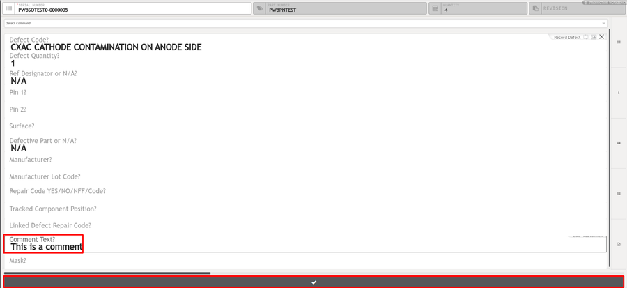
Note: Notice that a comment field has been added to the serial number.
Figure 45: Adding a Comment
Note: Users are able to add a comment as an additional operation (enclosed with a red rectangle) as seen in Figure 71.
Disable Additional Operation
In the next step list, users will see how to use the Disable Additional Operation functionality:
- Scan the serial number.
- Click on the Select Command dropdown menu and enter the value Record Defect.
- A list of commands will be displayed, select the Record Defect command.
Figure 46: Add Record Defect
- After selecting the command, select the Complete Selection button to close the drop-down list and add the command values.
Figure 47: Complete Selection Button
- In the Defect Code field, enter the defect code (e.g. CXAC) to display the available options.
- Select the Defect Code e.g. CXAC CATHODE CONTAMINATION ON ANODE SIDE.
Figure 48: Adding The Defect Code
Figure 49: RepairDefect Additional Operation Fields Displayed
Note: Notice that the RepairDefect field has been added to the serial number.
Figure 50: Adding a Linked Defect Repair Code (RepairDefect)
Note: Users are able to add a Linked Defect Repair Code on the first field enclosed with a rectangle, whereas on the second field enclosed with a rectangle,
users can’t enter any information, but when users submit this form, both fields will have the same value that corresponds to the first field.
Replace PTS Component Tag
Users have the option to replace old PTS components ID that were once configured previously with new components ID param for the additional operations.
In order for the option to replace old components to be available users must enable the flex field for ReplaceOnBoardPtsComponent.
To enable, go to Shop Floor Control > Configuration > Shop Floor Configuration.
- Select the Defect Code option.
- Select the check box beside the corresponding defect code desired within the list.
- Click Edit.
A defect code form pop-up box will appear, users should locate the FlexField Form tab. The additional_operation box should have ReplaceOnBoardPtsComponent labeled inside.
- Click Save.
Once the feature is enabled, users will be able to use the Production Workbench to replace Component ID. Go to:
- Insert the serial number within the serial number box.
- Type “Record Defect” and select that option in the drop-down box below.
- Click Enter.
Once the FlexField is enabled, two forms will then be available for users to input information within the section of questions for Production Scanning.
A selection of questions will appear below for the user to insert information such as :
- Defect Code
- Defect Quantity
- Ref Designator
- Site ID
- Component ID
- Old Component ID
- Remarks (Optional)
Note: The defect code is registered through a previous flexfield configuration.
- Insert the Defect Code.
- Insert the Ref Designator.
- Insert Site ID.
- Insert Component ID.
Note: The component ID should already exist in PTS.
- Insert Old Component.
- Insert a remark (optional).
- Select the checkmark box.
A successful message will appear that the “Current Board Reworked Successfully” if the information was inserted correctly.
Building the Transaction
42Q uses the term “transaction” to mean everything that is recorded at the scanning terminal and sent back to the MES.
For example, when the Operator scans a unit’s serial number, records attributes, and adds/removes a component, this is called a transaction.
Sending a termination command sends the transaction back to MES and moves the unit to the next PASS/FAIL location.
Transactions can be saved at any time before ending the transaction.
The 42Q MES creates a new transaction each time a serial number is scanned.
All information about that unit is collected together and sent as a single transaction when a terminator command (i.e. END, MOVE, Sample Unit) is sent.
This eliminates the chatty protocol between the client and the backend that creates a transaction for each bit of information.
An effect of this ACID transaction system is that 42Q validates data together instead of step by step.
For example, if the Operator scans 15 serial numbers as a batch and one of them fails, the entire transaction fails.
To build a transaction:
- Select the Data Collector drop-down to display a list based on whether Location/Process/Device was selected during the initial configuration.
- Select the desired Data Collector from the list.
Note: Ensure that the selected location is the correct scanning location. If a serial number is scanned at an incorrect location/process, a flow error will display. - Enter/Scan the serial number. Any documents mapped to the part number at the current scanning location will be displayed.
Figure 51: Document Display list.
Note: If there are multiple mapped documents, they can be selected from the drop-down menu. The default document is configured in the Document Mapping portlet.
- If defined, attributes and components will be prompted for according to their defined Step Number.
Note: For defined attributes or standard/unique components, if the entered data does not match the defined mask, an error message will display.
Removing an attribute or a component that has already been submitted will return the prompt to the list. Prompts can be answered in any order, but the transaction cannot be completed until all prompts have been answered correctly.
Note: Operators can submit information at any time to save the entered information. Saving does not complete the transaction but will store the entered information for later use.
- If there is a defect to record, select Record Defect from the Command list.
- Enter the Defect Code and all other necessary data.
Figure 52: Record Defect Zoomed.
- If desired, add commands from the Command drop-down menu.
- Ensure all information is valid and entered into the appropriate fields.
- To end the transaction, add the END command from the Command list when the unit is ready to be moved to the next location.
- Select the Submit button. If the submission PASSES, a PASS TO message will display. If a defect was recorded, the unit will FAIL to the specified FAIL TO location and a FAIL TO message will display.
ps_duplicable_promt_component_type
The ps_duplicable_promt_component_type is a new Generic Attribute that indicates what type of assembly can be copied or cloned. Only these two component types are supported: Consume from NSB and Non-Tracked with Quantity.
Note: If the user enters a component type that is not supported it will be ignored.
For more information please refer to the Generic Attribute Maintenance.
Containerization
This Topic will guide the user on how to work with Containers.
Before creating a container here, there is a pre-configuration in the Multi-Level Containerization Configuration module. See below how to configure a container:
- To access the Multi-Level Containerization page, navigate to Shop Floor Control > Configuration >Multi-Level Containerization Configuration.
- The main Multi-Level Containerization Configuration page is displayed.
MLC Config: Creating a new Container Configuration
To create a new Container Configuration, select the Add button located above the container level list on the Container Configuration Maintenance main page.
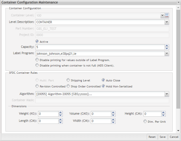
- The Container Configuration Maintenance window is displayed:
The following fields are displayed just for containers >100:
- Container Level
- Part Number
- Project ID
The following checkboxes are displayed as Multi-Level Container Rule:
- Revision Controlled: If selected only one revision can be containerized together. Please correct and check the default value.
- Shop Order Controlled: If selected only units from a single shop order to be containerized together – default No;
- Shipping Level: If selected, defines that a specific container is the Shipping level of containerization – default No;
- AutoClose: Yes / No – defaultNo;
- Multi-Part: Allow multiple part numbers in a container. It is possible to add elements from another part number, but it must have the same Project Id.
- Hold Non-Serialized: Allows users to use a different command when they want to add Non-Serialized Batch to the container.
The user can define the Container Dimensions by entering the weight (kg), height (m), length (m), volume (m3), and width (m). Selecting the Dimension per Unit flag, it is possible to fill for each configuration container.
If the dimension is in different measures, the data will be converted.
Two new fields are available under the Validation section: Close Container and Add Element.
These Combobox were created to allow users to add validations different from the default ones. The values in these fields are all Operations available for a specific Site/Plant that are configured by Customization, according to their needs.
The user only needs to select which operation will be assigned. The Operations should be assigned to one Tag, previously in order to be displayed on the options list.
Note: Container Level 99 does not allow users to configure a custom validation.
After this pre-configuration, the user can go to Production Workbench and create a container, add serialized units and non-serialized units, Remove serialized and non-serialized units.
Create a New Container
To create a container at ProductionWorkbench follow the steps below:
Select the Create Container command from the drop-down menu and select Enter;
- Enter the Container Level, in this case, 100, previously configured at MLC Container Configuration module
- Enter the Container PN.
- Enter the Project ID, also configured at MLC Container Configuration module.
- Select the
 Save button.
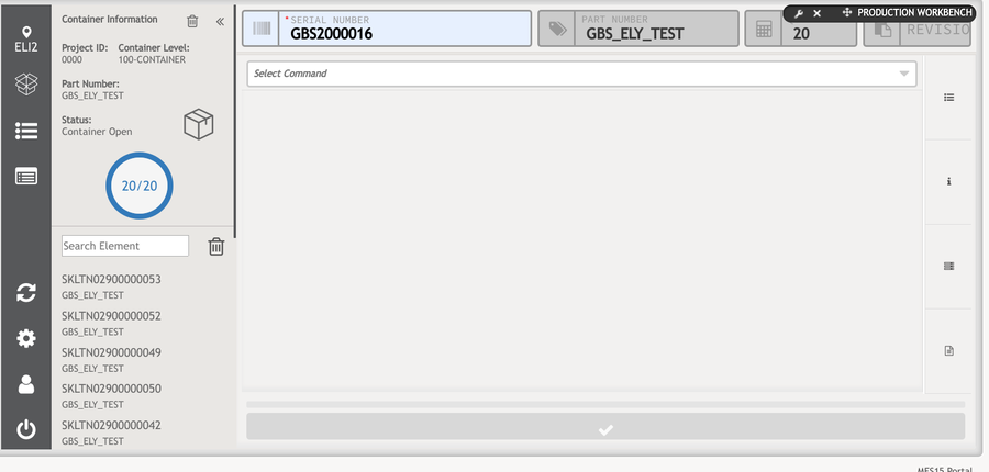
The created container is displayed on the left side of the page and the user can see the Container information with quantities. A success message will be displayed;
Create Container - Require Automatically the Serial Number
When the user creates a container in the regular mode, it is necessary to select manually the command Add Unit to the container. With this functionality, it can be done automatically and displays the command until the user completes the container.
The container will be created and display the information on the page, adding automatically the command that is configured on the Generic Attribute Application named "ps_container_command".
The value for this gen attr is a name or pretty_name for a command. See the example for Add a Unit without part number:
The default Value value for this Gen Attr is EMPTY and the command that is configured will be added by default to the container's functionality.
Figure 53: Require automatically the Serial Number
Auto-Populate the Container Information
To use the Auto-Populate container functionality, it is necessary to open the Container Information panel select the container icon at the left side of the page and the container information needs to be cleaned.
When the user scans a serial number in status complete, a window will be displayed and the user will be able to select a configuration to create a new container.
This window only will be displayed when doesn't exist a previous configuration is selected or the SN scanned doesn't match the current configuration selected (This option is showing on the top of the container panel)
When the user chooses an option and click on the submit button ![]() the container will be created and after the process will continue.
the container will be created and after the process will continue.
PW - Add Non-Serialized Units
After creating the container, it is allowed to add units to it. To add non-serialized unis, follow the steps below:
- Select the Command Add Non Serialized to Container;
- Add the Unit Part Number and Quantity;
- Select the
 Save button;
Figure 54: Add Non-Serialized Units Data
The unit added to the container is displayed on the left side of the page. The user can see the Container information with quantities and a success message is displayed;
PW - Add Serialized Units
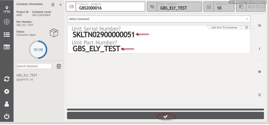
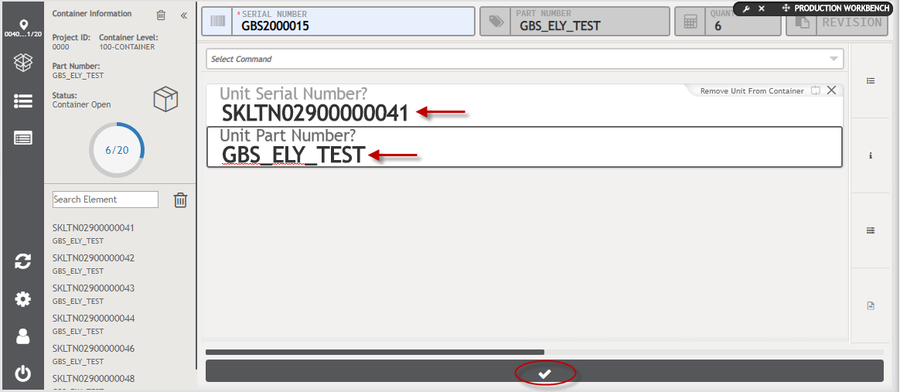
After creating the container, it is allowed to add serialized units (serials associated with shop orders) to it. To add serialized units to the container, follow the steps below:
- Select the Add Units to Container command;
Figure 55: Add Serialized Units Data
The serialized unit added to the container is displayed on the left side of the page. The user can see the Container information with quantities and a success message is displayed;
PW - Remove Serialized Units
To remove serialized unis from the container, follow the steps below:
- From the container, select the Remove Unit command from Container or select the
 Remove icon;
 - Enter the Unit Serial Number and Unit Part Number;
- Select the
 Save button;
Figure 56: Remove Serialized Data
A success message is displayed and the unit is removed.
PW - Remove All Serial Numbers from Container
It is possible to remove all serial numbers from the containers according to the profiles configuration.
This option is the remove ![]() icon on the right of the Search field.
icon on the right of the Search field.
Note: Only users with Supervisor Profile can remove all the information from a container in one shot.
PW - Remove Non-Serialized Units
To remove non-serialized unis from the container, follow the steps below:
- From the container, select the Remove non-Serialized from Container command;
- Enter the Unit Part Number and Quantity to be removed;
- Select the
 Save button;
Note: If the user wants to remove the total quantity, he can select the ![]() Remove icon
Remove icon
A success message is displayed and the non-serialized Unit is removed.
Container Profiles
To give permissions to remove elements from a container, users can enable the profiles "Remove Element" and"Remove All Elements".
- Select a container from Profile Maintenance.
- Click on the Define Permissions button at the top of the section.
- Mark the correspondent boxes of the profiles Remove Element/Remove All Elements that are inside the Container widget of Production Workbench portlet.
When these profiles are disabled, a Supervisor login will be required.
PW - Pagination
If the list of units has more than 15 items, pagination will be displayed and the user will be able to browse the pages.
Figure 57: Container Information - Pagination
PW - Filter by a Specific Element
To help users find specific elements in a very large list, they can type the element in the Search Element field and select Enter.
Figure 58: Filter by a specific element
PW - Close/Autoclose Container
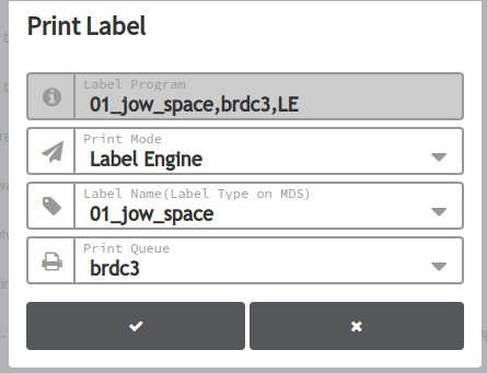
When the container reaches the capacity, the Print Label page is displayed, automatically filling the fields with the Label_Program field on the container configuration following the next structure:
Also, the user can close the container when clicking on the new close container ![]() icon and the printer panel will be displayed if it is configured properly.
icon and the printer panel will be displayed if it is configured properly.
Figure 59: Close Container Using the Close Container Button
LabelName (LE) or LabelType (MDS), PrintQueue, ModePrint (LE or MDS)
Figure 60: Print Label
Select the submit ![]() button when you want to send the print.
button when you want to send the print.
Figure 61: Container Configuration
The option for this printing is done automatically by adding to the end of the structure the following LabelName (LE) or LabelType (MDS), PrintQueue, ModePrint (LE or MDS), Auto Close
Note: that the user can open the container if the capacity is not completed.
Users can disable printing partial labels if a container is not full by selecting the corresponding box in the Label Program section of the Container Configuration Maintenance.
Note: To print a partial label, the operator should close the container by clicking on the box icon located beside the container information.
PW - Refresh Upon Autoclose Container
When the print is done or the user cancels the print, the page is refreshed just showing the work log:
Packing Control
This function validates that all serials belonging to a certain container have a specific component, if it does not have it, it has to be rejected.
Another functionality is that when the serial is located in PACKING, for instance, and users scan it, it will be passed to COMPLETE and it will be passed only in one scan. It also validates the processes from which a unit has passed through.
There are two requirements in order to use this functionality, the first one is that the generic attribute: ps_inline_packing_station must be active. The values should be yes/true/no/false.
Attributes activation is performed at Administration > Generic Attribute Maintenance as in Figure 116.
The second requirement is that the Autocommands for PACKING location, that is, Prepend and Append must be enabled, depending on which one user will need.
Activate Generic Attribute “ps_inline_packing_station”
To perform the Packing Control functionality, follow the next step list:
- From Production Workbench, select the Container Information icon.
Figure 62: Container Information Icon
- Select the Configuration icon.
- Click on the Advanced option.
- Mark the Packing Station checkbox.
- Click on the Tick icon to save changes.
Figure 63: Packing Station Checkbox
Note: Notice that when the Packing Station generic attribute is active, a new field will be displayed in the Container Information portlet.
Enable Prepend or Append Autocommands
Prepend: When moving a unit to PACK, this Prepend option moves the unit to COMPLETE and then enters the unit into the container.
Append: This option is triggered after you enter the command END to the unit.
This Append option moves the unit to PACK, next moves it to COMPLETE, then enters the unit into the container, and afterward users can do more operations, add a comment, for instance.
To enable the Prepend or Append Auto Commands, refer to the next document: Command Register
Note: Follow the instructions of the Command Register SOP as well as the next steps:
Within the Command Register portlet, after selecting the Auto Commands tab, users have to enter the value PACK PACKING in the Location field, then select a Packing Station in order to display its Auto Commands and finally enable it.
QCP Checklist
The QCP Checklist functionality allows the Production Workbench users to access a set of pre-configured checklists for specific:
Location, Process, Location by Part Number, Location by Shop Order, and Location by User.
To display the QCP checklist, the users must select either a Location or a Process on the Production Workbench,
depending on the previous configurations done by the supervisor in the QCP Configuration Portlet; once selected, the QCP checklist is displayed on the screen.
The QCP checklist displays the questions configured previously. Those fields marked with a * (red star) are mandatory. These questions can be set:
- By multiple choice, text, number (with or without decimals), specific date/date range, or mask
- With possible expected/right answers so that the system can validate what users answer
- With answer’s expiration time as “Answers Never Expire” (when the configuration is done by shop order)
- With an attached image per question to help operators when answering questions
Note: Please refer to the QCP Configuration documentation for more information.
Figure 64: Production Workbench QCP Checklist
Note: Users can maximize the screen using the arrow icons on top of the screen, as described in the image above.
Figure 65: Production Workbench QCP Maximized Screen
Note: The user must complete the checklist to be able to scan the Serial Number, if the user tries to scan before completing the checklist an error will occur as displayed in the picture below.
Please refer to the MFG Hold Maintenance documentation for more information.
Once the QCP checklist is complete, the user must click on the submit button; the system will reload automatically, saving the user from having to add the Serial Number again.
Figure 66: Production Workbench QCP Checklist Submit
Note: The QCP checklists are saved into the domain action, to see the questions and answers please refer to the QCP Checklist in MESWeb.
After users submit their answers, the system will display a QCP checklist summary that shows if the answers are correct or not.
Figure 67: Production Workbench QCP Checklist Submitted
In case the answers were incorrect, the system holds the process, until a QC Auditor user decides what’s next. Only QC Auditor profiles have permission to run the line under failed conditions. They can:
- Add justifications before:
- Re-open a current QCP checklist
- Approve with failures
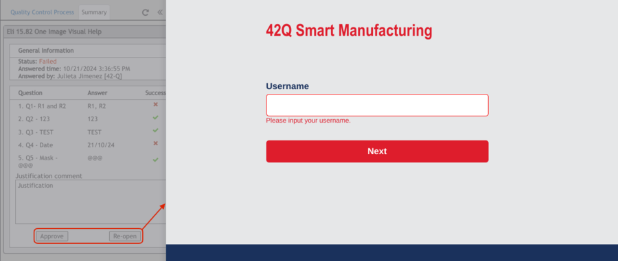
If a user without proper permissions selects the Approve or the Re-Open buttons, the system will display the universal login screen, so that a QC Auditor can access and proceed with any of these actions.
For further information about how to define permissions, please refer to the section “Profile Maintenance” of this document.
Figure 68: Universal login
Enable or disable QCP Checklist and Labor Tracking interaction
Users can enable or disable the interaction between QCP Checklist and Labor Tracking through the configuration of the generic attribute “ps_qcp_hold_lock”.
If the “ps_qcp_hold_lock” generic attribute is configured as “True” in Location or Process, users cannot execute the following functionalities, until they answer the checklist:
- Track direct labor (but they can report indirect labor)
- Input attributes or assemblies information
If “ps_qcp_hold_lock” is configured as “False” in Location or Process, the QCP Checklist is not mandatory and users can execute normally Production Workbench.
Note: For further information about:
- Generic attributes, please refer to the Generic Attribute Maintenance
- How to configure QCP Checklists, please refer to QCP Configuration Portlet
Multimedia Files
Production Workbench supports Multimedia Data Collection (PDF, Imagen, and Video).
Users can take photos using their computer or tablet camera and upload any multimedia file by selecting the camera ![]() icon to take a photo or theupload icon
icon to take a photo or theupload icon ![]() to upload any multimedia file.
to upload any multimedia file.
These new features are a great aid to provide evidence of the assembly process and to make sure protocols have complied, especially for big machinery that can take longer to assembly, or in case a unit needs to be repaired.
Note: Users have to select the new Generic Attribute ps_media_file_allow in order to input the format they want to be accepted to upload.
The administrator needs to configure the data type (MIME Type) in Type/Subtype format, for more information please refer to the Generic Attribute Maintenance.
Convert Attribute to Media Type
To add and define an attribute for this process, users have to reference in which part of the process the photos and or files will be attached,
identifying them in the system as multimedia attributes and how this photo/file is going to be referenced in the Unit History.
The attribute can also be configured inside Production Workbench by selecting Command > Add Attribute, once Add attribute appears in the top field click on the complete section icon.
Figure 69: Attribute in Production workbench
Once the complete section button is selected it will redirect to a different page, users then have to select the Record Media icon.
Figure 70: Record Media
The upload and camera icon will appear on the page.
File Upload
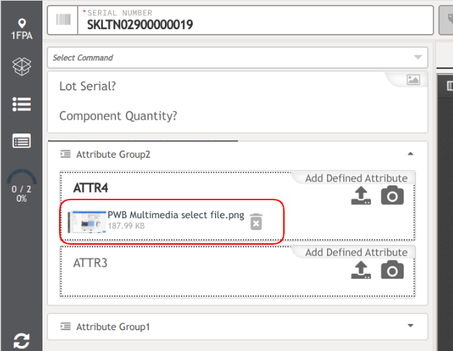
To upload a file from the gallery, first select the arrow icon inside the previously selected chapter.
Once selected, users are able to choose a file from their gallery device by selecting it and clicking open;
users are also able to drag and drop the files from an open folder in their computer or mobile device.
Figure 71: Multimedia Files, Select File
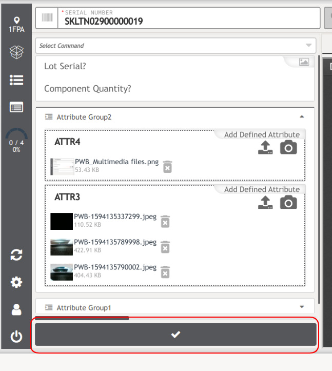
Once the file is uploaded to the attribute group section in Production Workbench, you are also able to remove it from there if needed by selecting the trash can icon.
Figure 72: Multimedia Files, Uploaded File
Take Photos
To open the camera and take a photo, first select the camera icon; inside the previously selected attribute Chapter.
Figure 73: Multimedia Files Camera
Once users have the camera open and the photo taken, the following options will be visible:
- Close
- Retake the photo
- Take another photo
- Delete
- Upload
Figure 74: Multimedia Files Open Camera
Note: It is possible to take and upload more than 1 photo at a time, but only when a computer is in use, this action won't be allowed when using a mobile device.
Figure 75: Multimedia Files Take Another Photo
These gallery options can have two scenarios for the operator;
- The operator takes the photos and does the assembly; to later upload the pictures.
- The operator takes the photos as they do the assembly/ repair process.
Once photos are uploaded and visible on the screen; you can submit them by selecting the Submit Button, as shown in Figure 143.
Figure 76: Multimedia Files Uploaded Photos
After submitting the photos, users would be able to the Success message on top of the page.
Advanced Configuration
Advanced Configuration is now available in the Configuration Panel, this new option provides filters for the information in the configurations ahead.
By selecting the Advanced option the complete configuration is displayed
The previous “advanced” option will be changed to Basic in order to return to the previous view.
Figure 77: Advance Configuration - Basic
Filters
The following filters are available in the Advanced Configuration Panel:
- Generic Attributes Filter
- BOM Item Type Filter
- Location / Process
Figure 78: Advanced Configuration: Filters
Note: In order to be able to see the configuration in Production Workbench, users have to set up the Generic Attributes by entering the filter's items in the flex field of the process:
Shop Floor Control > Configuration > Shop Floor Configuration > Location > Process Maintenance > Add>Flex Field and use the following fields:
- bom_item_filter
To filter the BOM items
- shop_order_attr_filter
To filter the generic attributes
- mapped_bom_item_filter
Set as true to filter the BOM items mapped to the location or process where the operator is working.
Note: In order to add more than an item to filter in a field, the items must be separated by a comma: e.g. item1, Item2.
The information in the FlexField will be loaded in the Advanced Configuration in Production Workbench.
Note: The selected configuration in Production Workbench Filters is loaded from the FlexFields every 24 hours.
Shop Order Sequencing
The Shop Order Sequencing is a new functionality that allows Production Workbench users to visualize the Serial Numbers that belong to a Shop Order; as long as the Shop Order type is different from a non-serialized batch (unit_type 8).
Users are able to see a new copy link ![]() button on the screen that allows them to copy the Shop Order number to the clipboard.
button on the screen that allows them to copy the Shop Order number to the clipboard.
When the user clicks on the copy link an Info! message will appear on the screen to confirm the number was copied successfully.
When users select Shop Order on the panel, the serial numbers in the queue available to scan on the selected Location or Process will be displayed on a list.
Note: The quantity list of the serial numbers in the Shop Order panel is defined by a new generic attribute: ps_shop_order_scheduling_serials_limit
For more information please refer to the Generic Attribute Maintenance
If the Shop Order contains more than the quantity configured, a SHOW ALL button is displayed on the bottom of the panel, allowing the user to see all the available serial numbers on the Shop Order once the button is selected.
Figure 79: Shop Order Sequencing List Show All
After all the available serial numbers are visible, a SHOW LESS button is displayed on the bottom of the panel; if the user selects this option only the configured quantity of serial numbers will be visible again.
Figure 80: Shop Order Sequencing List Show Less
Note: Users can select a serial number from the list by clicking on it; the serial number will be automatically scanned.
When the queue quantity is in the Shop Order Panel and the user clicks on the panel, the serial number will be automatically scanned.
Figure 81: Shop Order Sequencing List: Quantity 1
Figure 82: Shop Order Sequencing List: Quantity 1
Users will see only one operation sequence mapped in a specific location at the moment that the Shop Order is released.
Figure 83: Only One Operation Sequence
Users are allowed to set up the time frame in which the scheduling panel will be refreshed. The default time frame is 60 seconds, but it can be changed to refresh automatically since 29 seconds.
Note: This functionality is available with the previous configuration of the generic attribute ps_so_scheduling_refresh_time. For more information please refer to the Generic Attribute Maintenance.
Figure 84: Refresh Rate
Shop Order Release Notes
Shop Order Release Notes is a new functionality that notifies users if there is Release Notes information in a Shop Order related to the scanned Serial Number.
This new SO Release Notes can be accessed by selecting the Release icon ![]() the right side of the panel.
the right side of the panel.
Figure 85: Shop Order Release Notes
The Release Notes icon will blink in blue to notify the user that the Shop Order has Release Notes information.
This behavior will persist for 30 seconds from the moment the user scans the serial number, however, if the user remains working over serial numbers in the same Shop Order, this behavior will not repeat between scan and scan.
Note: If the Shop Order does not contain any Release Notes the icon ![]() will be gray and once the user opens the Release Notes the icon will also be gray out.
will be gray and once the user opens the Release Notes the icon will also be gray out.
Once users select the Release Notes Icon a menu will appear showing the Shop Order, Release Notes, Generic Attributes, and the BOM Information.
The information listed above are collapsible menus, users can expand these by clicking on each tab.
Shop Order Menu
Once the user clicks the Release Notes (blue) icon, the Shop Order information will be displayed in the information panel with the following collapsible sections:
Shop Order Information
- Shop Order Number
- Revision
- Part Number
- Start Date
- Completion Date
Figure 86: Shop Order Release Notes Information
Note: The Release Notes are supported in HTML format, this functionality depends on how the user loads the information into the release notes.
Production Workbench is not responsible for the information inside the links in the Release Notes.
Generic Attributes
The Generic Attributes and values will be displayed alphabetically.
BOM Information
The BOM section displays the following steps:
- Part Number
- Quantity
- Description
- Revision
- Item Type
- Step
Figure 87: Shop Order Release Notes: BOM
Document Mapping By URL Based On Order Attribute
With this new feature, users can display an HTML page in the Document Window of Production Workbench. For more information, please refer to the Admin Document Control.
Figure 88: Video from an URL
Figure 89: HTML page from an URL
Labor Tracking
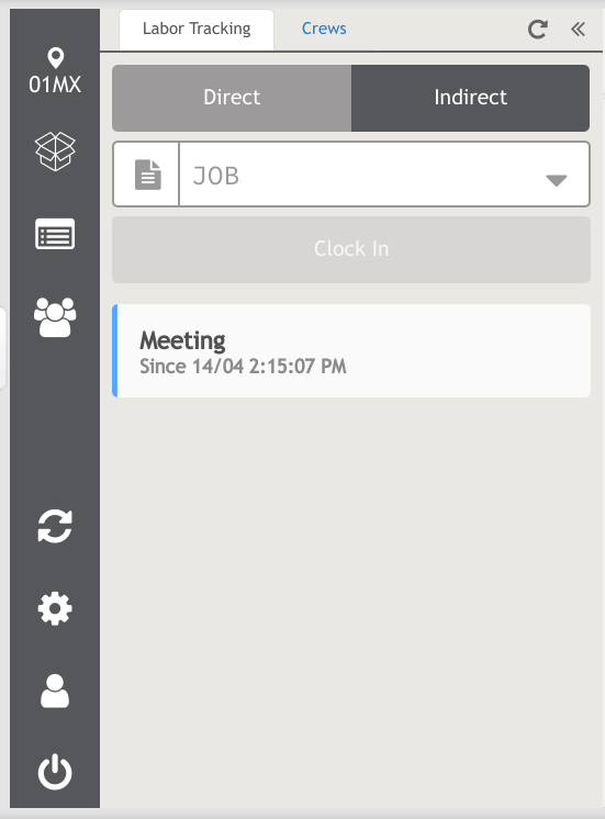
Users will be able to see an icon in the left side panel called: Labor Tracking | Crew ![]() .
.
This functionality allows users to view the list of shop orders assigned to the location operators are working on, collecting the time the operators spend in the current operation as well as see the available crews.
Once this option is selected, users will be able to visualize the two widgets Labor Tracking and Crews.
Figure 90: Labor Tracking and Crew Tabs
Note: Users are able to move from one widget to another.
Labor Tracking Widget
In Labor Tracking there are two different types of labor, Direct and Indirect, Direct Labor refers to the activities related to the manufacturing process i.e. machine setup, machine running, and change over.
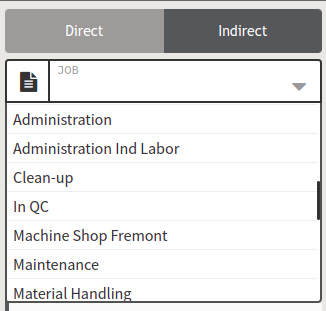
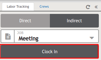
Indirect Labor refers to administrative activities non-related to manufacturing i.e meetings, breaks, training, and cleaning.
Direct Labor
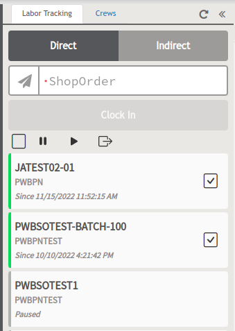
In the Direct Labor Panel, users will see a list of jobs that the operator is working on, grouped by shop order.
Users may notice that if they click on a shop order, the serial numbers that belong to that shop order will be displayed below, if users click on a serial number, that serial number will be automatically scanned.
Note: Scanned shop orders will be added to labor tracking with the serial numbers related to it, and they will be assigned to the user who scanned them.
Smart Insights
This feature makes the operator able to Clock-In, or Clock-out a shop order manually when the Smart Insights pop-up window displays.
If the user scans a serial number that belongs to a certain shop order (e.g. PWBSOT0-00001) Smart Insights will display, so the user can Clocks-In that shop order, but then,
if the user scans another serial number belonging to the same shop order (e.g. PWBSOT0-00002) Smart Insights will not display, instead, Production Workbench will add the time of the first shop order to the second shop order
and then recalculate the time to complete the task.
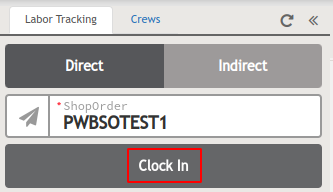
To track a direct shop order that is a Non-Serialized Batch, just enter the job number in the Shop Order field, and then, click the Clock In button or press the Enter key; the Smart Insights pop-up window will appear in the upper right corner.
There will be three options available:
- Clock-In / Resume: Starts to track the time of a shop order, and adds it to the panel as seen in Figure 167, or resumes a paused shop order.
- Clock-out / Resume: Stops the time tracking of a shop order or resumes a paused shop order.
- Dismiss: Closes the Smart Insights pop-up window.
- Dismiss and Don't Ask Again: When this option is selected, the Insights checkbox will appear. With this option, all scanned or ended units will not trigger the Smart Insights pop-up window nor will the unit be time-tracked.
This configuration is saved in the local storage and it will only be applied to the physical station, it will not be propagated to all Locations or Processes.
If the user marks the Insight checkbox the Smart Insights pop-up window will appear again.
There are two ways to configure the Smart Insights feature:
- Based on a generic attribute (configured at the Generic Attribute Maintenance portlet): The generic attribute: ps_insights_enabled can be turned on and off (using the values: true or false).
This attribute triggers the Smart Insights feature as a site-level configuration.
2. Based on a FlexField in the Location or in the Process (configured at the SFDC Configuration portlet)
In cases where the user needs to track time only in a Location (e.g. INSP Inspection), the user must use the FlexField: ps_labor_tracking_option set to the next value: insights or off.
When this attribute is set to insights, it triggers the Smart Insights feature only in that Location, not in the whole system. On the other hand, when the attribute is set to off,
the Smart Insights feature will appear in the whole system except for one Location.
When the FlexField: ps_labor_tracking_option is set to: AUTO. With this configuration, it doesn't matter if the FlexField is set to ON or OFF.
When the user scans a serial number, it will be automatically added to the shop order list, and if the END command is entered, that shop order will be Clocked-Out.
This option only applies to the Location or Process.
When users are working with a Location, and they want to overwrite the generic attribute, they must use the location Flexfield, but if they are working with Process or Devices, they must use the Process FlexField.
When the user is working using Devices, the only difference is that the operator will be able to see where the shop order was tracked from.
Figure 91: Adding a Shop Order To Track
Non-Serialized Batch
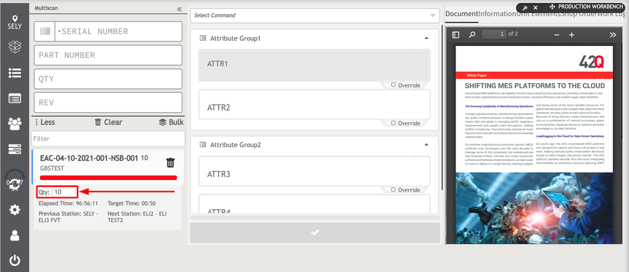
These are shop orders that work by batch; The quantity of the batch the user will work with can be filled out by the users on the QTY field in the Production Workbench header as in Figure 168.
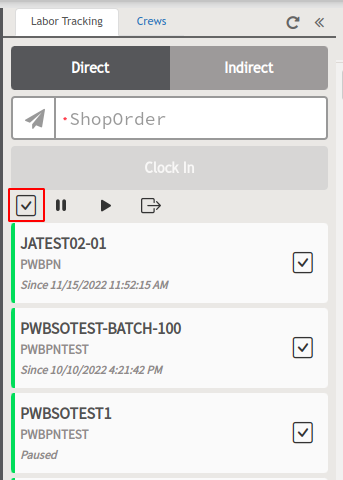
Users can perform three different activities to one or multiple shop orders and serial numbers, either by using the Select All checkbox or manually selecting each of the checkboxes.
Note: Active direct labors are marked in blue color and Paused labors are marked in gray color. (see Figures 169 and 170). Direct labor time is not running if the serial number or shop order is selected on Pause; the serial number and shop order will still be visible on the list.
Note: This applies to all labors with status paused (see Figures 171 and 172). Direct labor time will keep running and the serial number and shop orders will still be visible on the list.
Note: The resumed labors will be marked in blue again. Direct labor will stop and the serial numbers and shop orders will be no longer displayed on the list.
After users click on any of the three activities, a confirmation message will appear, select Yes to do the action or No to cancel.
Recording Labor for Multiple Shop Orders
Users have the capability to work with multiple shop orders by selecting the Select All checkbox, all shop orders assigned to the workstation will be selected and marked in green.
Figure 93: All Shop Orders Selected
Users have the capability to work with multiple shop orders by selecting the checkbox of specific shop orders assigned to the workstation.
Figure 94: Multiple Shop Orders Selected
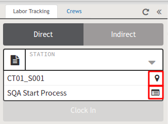
When the Production Workbench is configured in Location mode, users will only see the JOB field but if it is configured in Device mode, users will see an extra field called STATION.
When users click on the STATION field, they will see two different types of icons:
![]() This icon indicates that it is a Location.
This icon indicates that it is a Location.
![]() This icon indicates that it is a Process.
This icon indicates that it is a Process.
Figure 95: Station Options
Indirect Labor
Users must click on the JOB field and select which type of indirect labor they’ll be working on, then click on the Clock In button;
if users have active direct labors, a confirmation message will appear to pause those direct labors in order to create the indirect labor; Click Yes to proceed or No to cancel.
On the other hand, when users Clock-out an indirect labor a confirmation message will appear, there will be 3 available options to select:
All: Resume all inactive direct labors.
Last activities: Resume the activities that were active the last time.
No: Cancel the action.
Supervisors have the option to add more indirect labor codes to the default list through Labor Tracking Maintenance. Once the added indirect labor has been registered, it will appear in the Indirect Labor drop-down list.
To learn how to configure them, please refer to the Labor Tracking Maintenance.
Figure 96: Selecting Indirect Labor
Figure 97: Clock In Indirect Labors
Figure 98: Active Indirect Labor
Note: Indirect labors marked in blue color are currently clocked in, whereas the labors marked in gray were recently clocked in.
Crew Widget
Users are able to see the current active crews, the users can join as soon as this option is selected, the active Crews will display the color blue on the side panel; the crew widget allows users to filter by Crew name, Crew members name, and employee ID.
Logged As Regular User
Logged as a regular user, the user will be able to see the Active crews and members listed there, the user can join a Crew.
Also, users are able to use the Filter field to enter a Crew name, employee name, or employee number, and the system will automatically find it.
Note: As a general rule a user cannot be part of two Crews at the same time.
Figure 99: Click On The Crew To Display The Member Name Found
Figure 100: Filter By Employee Number
Figure 101: Click On The Crew To Display The Employee Number Found
Without using the filter, the system will show the latest Crew the user was working at the top of the list;
users can join a Crew by selecting it but if users have pending labor, the system will prompt to confirm if the user wants to pause the current labor and join a new Crew.
When clicking Yes, a Confirmation Message will pop-up at the top of the screen, letting users know they joined the crew successfully.
Once the user joins a crew, the information on the panel will change and show only the crew name the user is part of, displaying the user name, employee ID, and the date the user joined the crew.
Figure 102: Regular User Panel, After Joining a Crew
On the other hand, if users want to leave a crew, click the Leave button that corresponds to said crew;
A Confirmation Message will pop up, click Yes to leave or No to Cancel. After that, the information on the panel will change back and show the previous one.
Note: Once users are part of a Crew they won’t be able to scan as themselves if they join a Crew, Conduit will block any request that comes with that employee.
Logged As Crew User
Logged as a Crew user, the Crew user will be able to see the current crew information (members listed there), the user can join a Crew.
Also, users are able to use the Filter by employee name, and employee number, and the system will automatically display the information by those parameters.
Note: As a general rule a user cannot be part of two Crews at the same time.
Figure 103: Crew User Login
For more information, please refer to the Crew Maintenance
Decoration Of The Items From The Shop Order And The BOM List
This functionality allows users to decorate, not only the shop order defined attributes, but also the defined attributes that belong to the part numbers contained in the BOM List.
Note: ‘Decorate’ means to set up the defined attributes in Mapping Document.
To use this functionality, users must enable the generic attribute value from Generic Attribute Maintenance, to do so, users must do the following:
- Access Generic Attribute Maintenance by navigating to Administration > Generic Attribute Maintenance.
- Search for the attribute name called ps_bom_attr_decoration_and_wi.
- Select the attribute name ps_bom_attr_decoration_and_wi.
- Click on the Edit Generic Attribute button.
- Change the parameter of the Value field from no to yes.
- Click the Save button.
Displaying Decoration Items
In Production Workbench, once the serial number is scanned, the attributes that were previously configured for this serial number will be displayed, users can click on the defined attributes in order to show the defined attributes’ work instructions.
Figure 104: Defined Attributes Belonging to a Part Number
Show Location
Production Workbench allows users the functionality to be able to search existing serial numbers and preview route information within the header section of the serial number.
In order for the functionality of displaying the Previous and Next location to become available in the Production Workbench, administrators must check the Show Location option within the Configuration Panel.
1. To enable this feature, click on the Configuration Panel tool button and enable the Show Location feature by clicking the checkbox.
Figure 105: Show Location Configuration
2. Click the check to save the changes.
3. Locate the Multiscan button on the left side panel and the multiscan selection page should appear.
4. Click the location icon and search for the location option needed.
5. Input and search the serial number in the search box.
6. Click enter.
Once the serial number is searched, it will appear within the Filter panel.
7. Click within the box of the serial number searched to preview the serial number’s previous and next station location.
Multi Scanning
The multiple scanning functions allow users to scan a batch of serial numbers at the same time.
To enable this functionality, click on the Configuration icon, select Advance, mark the Multiscan check box and finally click on the tick button icon to save changes.
Figure 106: Enable The Multiscan Functionality
Click on the Multiscan icon to open the interface.
Scan a Single Serial Number
Scan a Serialized Number
To scan a single serial number, users must enter a serial number in the input field, and press Enter.
Figure 107: Entering a Serialized Number in the Input Field
Figure 108: Serialized Serial Numbers List
Non-Serialized Batch
To scan a non-serialized number, users must enter a serial number in the input field, and press Enter.
Figure 109: Entering a Non-Serialized Batch Number in the Input Field
On the other hand, to scan and split a batch serial number, users must enter a serial number in the input field, and click the More icon to show more options, then, to split the quantity of the batch serial number, enter a quantity number, and press Enter.
Figure 110: Show More Fields
Figure 111: Split a Batch Serial Number
After that, the non-serialized batch will be scanned and will be added to the serial number list. Users will be able to edit the quantity of each serial number contained in the list.
Figure 112: Editable Quantity Number
Scan Multiple Serial Numbers
To scan multiple serial numbers, users must follow the next step list:
Select the Bulk option; a pop-up window will display.
Figure 113: Bulk Option
- Enter the serial numbers (one per line).
- Click the Scan button to scan all the serial numbers, or click Cancel to abort.
Figure 114: Scan Button
Note: After clicking the Scan button, all serial numbers will be scanned and listed.
Figure 115: Scanned Serial Numbers List
Add a Bulk of Serial Numbers to the List
Only users with an Administrator profile will be able to visualize, and therefore use the Bulk button as seen in Figure 216. The Bulk button provided will list the serial numbers, however, they will not be scanned.
Note: The serial numbers list will not show any information (documents, attributes, cycle time progress bar) they will only show in the list.
Figure 116: Bulk Button
Multiscan Actions
There are multiple actions that users can perform to manage serial numbers:
- Clear: Click this button to delete all the serial numbers listed or only serial numbers with an error.
- Trash: Click this button to delete a specific serial number.
- More: Click this button to show the Part Number, Quantity, and Revision fields. Click Less to hide them.
Figure 117: Multiscan Options
Tip: When users click on the Serial Number field, and then hit the Tab key, the field will be swapped to the next hidden field subsequently (PART NUMBER, QUANTITY, REVISION).
To delete serial numbers with an error, select the Clear option, then, a pop-up message will display, giving the users two options: to delete All listed serial numbers or delete SN/Error (the serial numbers with errors).
Override a Serial Number
When users enter a command, that command will be applied to all the listed serial numbers by default as seen in Figure 221 and 222, but in case users want to modify the value of a specific serial number, users must select that serial number, mark the Override checkbox, and then, modify the value as seen in Figure 223.
Note: The serial number in Figure 223 and 224 have the same Comment Attribute value because the Apply to all option is marked.
Figure 118: First Serial Number
Figure 119: Second Serial Number
Figure 120: The First Serial Number Is Overrode
Figure 121: The Second Serial Number Is Not
Note: The serial number in Figure 223 has a Comment Attribute value but that value was not applied to the serial number in Figure 224.
Note: When users scan a serial number in Multiscan, it will be added to the Direct Labor list (from the Labor Tracking | Crews widget).
Single Transaction
This configuration allows running units one by one when the “Multiscan” option has been selected. To configure the Single Transaction option:
- Open the Advanced Configuration Panel.
- Tick the Single Transaction box.
- And select the ok bar to proceed.
Figure 225: Single Transaction Configuration


