42Q-MES0171-A Work Instructions
42Q Home > Administration > Work Instructions
Administration
Work Instructions
Version MES 15.76
Revision D1
Contents
- 1 Introduction
- 2 Work Instructions Mapping
- 3 Work Instructions Search Doc
- 4 Work Instructions Type
- 5 Email Notification Management
- 6 PCB Engineering Notes
Introduction
The Work Instructions module allows users to map instructions to specific part numbers and processes. These can be an URL, HTML, documents, or embed HTML videos. Work instructions provide more details than a procedure because they contain specific instructions to carry out an activity. Their goal is to outline the steps to assign appropriate documents to the end-user regarding a process or part for which they require instructions.
To access the Work Instructions menu from the 42Q portal, navigate to Administration > Work Instructions. In there, these other folders are available, each one with specific features:
- Work Instructions Mapping
- Work Instructions Search Doc
- Work Instructions Type
- Email Notification Management
- PCB Engineering Notes
Figure 1: Work Instructions Menu
The next sections will give details on how the Work Instructions works.
Work Instructions Mapping
Search for previous mapped Work Instructions
Users can find any record that has been created before by using the searching fields located at the top of the window. The information will be displayed automatically in the panel below, once the user fills in any of the fields. To add or quit other field options, use the +MORE button.
Figure 2: Search Work Instructions
View panel
Users can choose the information that they want to see in the panel, distributed in different columns. The following are the available categories:
- Part Number
- Part Family
- Process Name
- Document Number
- Source
- Source Type
- Document Name
- Document Type
- Start Page
- End Page
- Revision
- Shown Default
- Attribute Name
- Assign
- Value
- Email Notification
- Direct From PLM
- Start Date
- End Date
- Batch ID
- Update Time
- Updated By
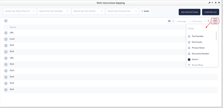
To chose which columns will appear, follow these steps:
- Select the three points located at the right top of the panel to display the different options.
- Then check the box or boxes of the selected category or categories. The selected columns will appear automatically with the corresponding information.
Figure 3: View Panel Menu
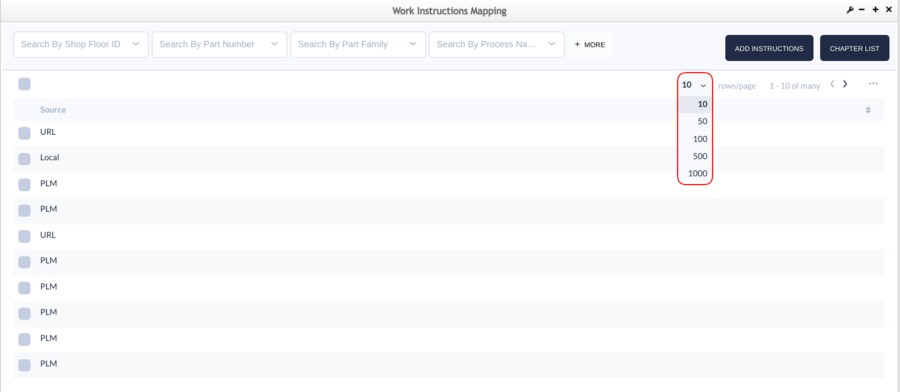
- To decide how many rows will be displayed, select the number menu at the top of the panel to see the different options.
Figure 4: Rows/Page Number Menu
Add work instructions
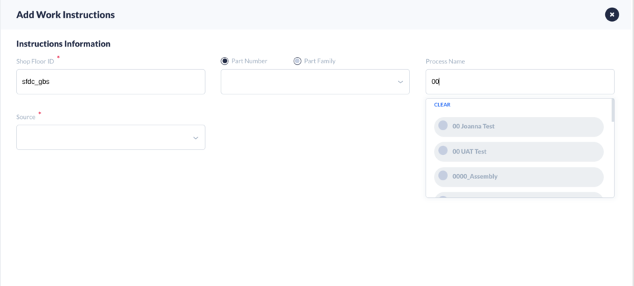
Users can map work instructions that can be seen in the Production Workbench when a Shop Order is scanned. As this is an intuitive tool, some new fields will appear upon users; add the information into the default fields. The Part Number, Part Family, and Process Name fields allow users to select multiple choices at the same time, in any case, the Batch ID field will appear automatically as mandatory.
Note: When a user enters more than one part number, part family or process, the Batch ID field will appear as mandatory.
Figure 5: Multiple Choices
To map work instructions, follow these steps:
- Select the ADD INSTRUCTIONS button located at the right top of the screen. The Add Work Instructions window will be displayed.
Figure 6: Add Instructions
- Input the required information.
- Select the NEXT button to open the next window.
- Complete the required fields and select SAVE to proceed or PREVIOUS to go back.
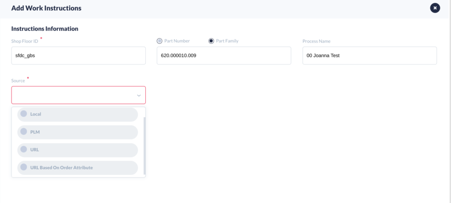
Source: In this field, users can select one of four options: Local, PLM, URL, or URL Based On Order Attribute. Each of them will ask for new information related to the source.
Note: Users are allowed to add URL/HTML documents or HTTP headers without any restrictions when the source is URL or URL Based on Order Attribute.
Figure 7: Source Options
- Local: It allows two Source Types and each requires different information.
- Document: It requires the attachment of a file, the Source Type, and the Document Type.
- Deviation: It requires the attachment of a file, the Source Type, the Document Number, the Document Type, the Value, and to specify if the deviation is assigned to a Shop Order, Unit Serial, Unit Quantity, or Lines.
Figure 8: Add Work Instructions - Source: Local Document 1
Figure 9: Add Work Instructions - Source: Local Document 2
Figure 10: Add Work Instructions - Source: Local Deviation 1
Figure 11: Add Work Instructions - Source: Local Deviation 2
- PLM: Requires Source Type, Document Number, Document Type (that can be created in the Work Instructions Type folder) and to indicate if it is Direct from PLM or not.
- To retrieve the existing revision of a PLM document, select the SEARCH button.
- To retrieve the newest revision of a PLM document, select the SYNC PLM button.
Figure 12: Add Work Instructions - Source: PLM
Figure 13: Add Work Instructions - Source and Type: PLM Document
Figure 14: Add Work Instructions - Source and Type: PLM Item
Figure 15: Add Work Instructions - Source and Type: PLM Deviation
Figure 16: Add Work Instructions - Source PLM fields 1
Figure 17: Add Work Instructions - Source PLM fields 2
- URL: Requires the address format of the URL (https://.com) and the Title of work instruction and Document Type.
Note: Validation is an optional functionality to support previewing the content of the URL.
Figure 18: Add Work Instructions - Source: URL 1
Figure 19: Add Work Instructions - Source: URL 2
Figure 20: Add New Header
- URL Based on Order Attribute: Requires the Attribute name(s) and Document Type. To map an URL Based on Order Attribute, users have to enter the Attribute name/Attribute names.
Note: Users can enter multiple attribute names separated by a comma.
Figure 21: Add Work Instructions - Source: URL Based On Order Attribute 1
Figure 22: Add Work Instructions - Source: URL Based On Order Attribute 2
Users can validate the configured attribute by selecting the Validation button (this is an optional step before clicking the Next button):
- Write down one or more Attribute Names separated by a comma.
- Input the Shop Order.
- Then select the Validation button. The system will list out all the found attribute names which users have inputted before.
- To preview the content of the URL, select the Link icon.
Figure 23: Shop Order and Attribute Validation
Case-insensitive for the Attribute Name:
- If users input several duplicate Attribute Names with the upper and lowercase, since the Attribute Name validation is case insensitive, the system will remove the duplicate Attribute Names to proceed with validation. Such as below three duplicate attributes, it will only verify the first attribute name.
Figure 24: Case Insensitive for the Attribute Name
- If users leave in blank the Attribute Names and input a valid Shop Order (e.g. CEB008), at the moment of selecting the VALIDATION button, the system will list all the corresponding Attribute Names related to this Shop Order.
Figure 25: List All the Attribute Names
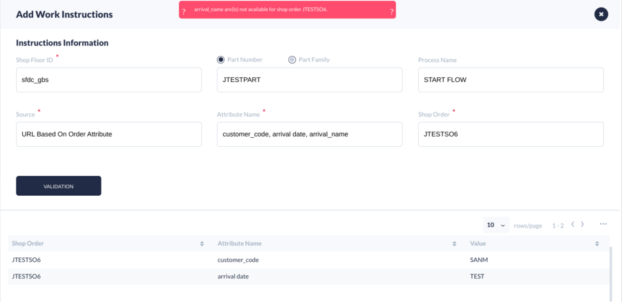
- If users input more than one Attribute Name, some of them will be transferred with the Shop Order (e.g. CEB008). Then, the system will list out those Attribute Names which have been found and, finally, alert those attributes that were not found with the Shop Order.
Figure 26: Invalid Attribute Names
Source Type: This field provides the type of sources to choose from. It appears automatically when the source has been previously selected as Local or PLM:
- GenCAD (this field will appear only if the process is empty when the source is Local)
- Document
- Deviation
Figure 27: Source Type Options - GenCAD
The following are optional fields to detail the information:
- Email Notification: It refers to the group name that has been set up in the Email Notification Management folder.
- Start Date: To indicate the day when the document mapping will begin.
- End Date: To indicate the day when the document mapping will end.
- Convert To: To convert .docx/.doc, .xlsx/.xls, .pptx/.ppt documents into PDFs, so that users can see the mapped documents in Production Workbench. This field will be Static Document when the file formats are .docx/.doc, .xlsx/.xls, .pptx/.ppt, otherwise, it will be blank.
- Start Page: To indicate in which page will begin the visualization of the document, as sometimes it can have too many pages.
- End Page: To indicate in which page will end the visualization of the document.
- Show default: To indicate if the work instructions will appear by default or not.
Note: If the start/end date is not specified, the set record will display the work for 10 years, by default.
Edit Work Instructions
Users are able to edit Work Instructions that have been added before by following these steps:
- Select a Part Number by checking the corresponding box.
- Then, select the Edit icon that appears when the cursor is located at the end of the selected row to display the Edit Document window.
- Edit the information and select the SAVE button to proceed or CANCEL to quit.
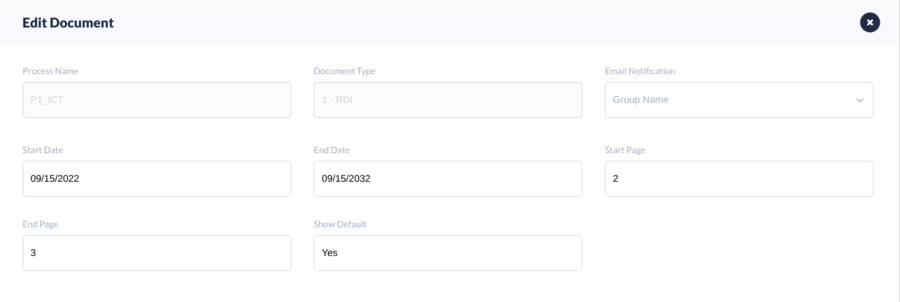
Figure 28: Edit Work Instructions
Figure 29: Edit Document Window
Delete Work Instructions
Users are able to delete Work Instructions that have been previously added following a few steps. They can delete one mapping record at a time, multiple mapping records, or all mapping records at the same time. To delete Work Instructions:
- Select one or more mapping records by checking the corresponding box.
- Then, select the Delete icon that appears when the cursor is located at the end of the selected row or the one that is located above the list, as shown in Figures 28 and 29.
- Confirm the action in the pop-up message to delete.
Figure 30: Delete one Mapping Record
Figure 31: Delete Multiple Mapping Records
To delete all the mapping records at the same time:
- Select the box located above the list of mapping records. All the boxes below will automatically be checked.
- Then, select the Delete icon located above the list.
- Finally, confirm the action in the pop-up message to delete.
Figure 32: Delete All Mapping Records
Preview Work Instructions
The system allows users to preview the URL that has been added as Work Instructions. To preview:
- Check the box of a chosen row.
- Select the Link icon located above the list or the one that appears by locating the cursor at the end of the row. With this action, the URL will be opened automatically in a new window.
Figure 33: Preview URL Work Instructions
Chapter and Step Lists
This functionality applies to users creating chapters and step lists for each Work Instruction. Users can find any record that has been created before by using the searching fields located at the top of the Chapter List window. The information will be displayed automatically in the panel below, once the user fills in Shop Floor ID, and Part Number or Part Family, and Process Name fields.
Add a Chapter List
Users can add, edit, or delete a Chapter List of a part number or a part family that specifies the steps to be followed and perform the information provided in the Work Instructions that have been mapped.
There are two methods to add a Chapter, one is by adding a chapter based on a work instructions mapping record, the other one is by adding a chapter directly without selecting a mapping record.
Add chapter list directly without selecting a mapping record
- The first step is to select the Chapter List button at the top of the screen.
Figure 34: Chapter List Button
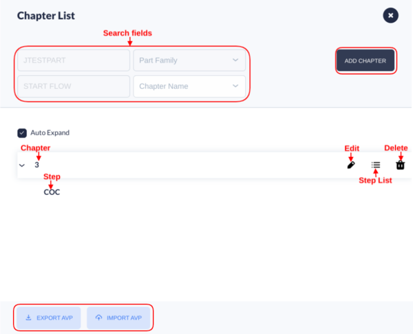
- The Chapter List window will be displayed without any general information.
Figure 35: Chapter List
- Click on the ADD CHAPTER button to display the Add Chapter window.
- Select the part number or part family radio button.
- Input the required information into the Chapter Information fields.
- Select SAVE to proceed or CANCEL to quit the action.
Figure 36: Add Chapter - Chapter Information Window
The chapters and steps can be displayed in the panel to easily locate a specific section by checking the box of Auto-Expand.
Add chapter list based on a work instructions mapping record
- The first step is to search and select a part number or part family by using the searching fields at the top of the screen.
- Tick the checkbox of any work instructions mapping record.
- Then, select the Chapter List button located on the right top of the panel. The Chapter List window will be displayed with general information about the Part Number or Part Family, and the process name that was chosen previously.
Figure 37: Work Instructions - Chapter List
- Click on the ADD CHAPTER button to display the Add Chapter window. The part number or part family, the process name, and step fields will be automatically populated.
- Input the required information in the blank fields.
- And finally, select SAVE to proceed or CANCEL to quit the action.
Note: Once the Attribute Group is selected, the steps of a chapter will be added automatically and they can be seen after the chapter is successfully saved.
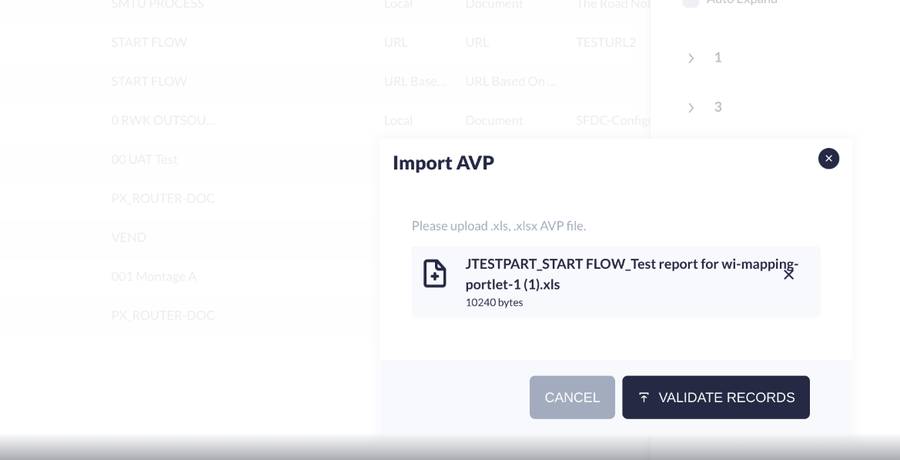
1. Click "IMPORT AVP" to import files.
Figure 38: Validate Records
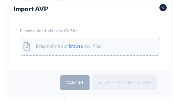
2. Insert the desired AVP browse files to import.
3. Click "Validate Records".
Figure 39: Import AVP
Edit a Chapter List
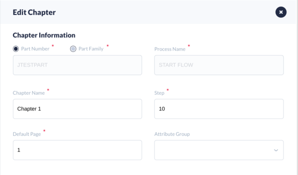
Users are also allowed to modify the information of a chapter such as chapter name, step, default page, and attribute group. To edit a chapter:
- Select the Edit icon that appears automatically when the cursor is located at the end of the chosen row.
- Edit the information of the fields.
- Then select SAVE to proceed or CANCEL to quit.
Note: If users create a chapter directly without selecting a mapping record, there won’t be a default page.
Figure 40: Chapter List - Edit Chapter
Figure 41: Edit Chapter Window
Delete a Chapter List
Users can delete a chapter by selecting the Delete option that appears when the cursor is located at the end of a chosen row.
Note: The steps will also be deleted accordingly.
Figure 42: Chapter List - Delete a Chapter
Steps from a Chapter List
The Work Instructions module has other intuitive functions that allow users to view, add or edit the Steps from a Chapter.
View Steps
To visualize the data steps, users can select the Step List button that appears when the cursor is located at the end of the chosen row.
Figure 43: Chapter List - Step List Icon
Figure 44: Chapter List - Step View
Add Steps
The incorporation of new steps to a chapter must be done in the Add Chapter window by adding an Attribute Group. Once done this addition, the steps will be successfully added.
- Open the Add Chapter Window.
- Input the required information in the mandatory fields.
- Enter an Attribute Group.
- Select the SAVE button. A confirmation message will appear at the top of the screen once the step has been successfully saved.
Figure 45: Add Chapter Window - Attribute Group
Figure 46: Message Confirmation - Saved Step(s)
Edit Steps
To edit a step from a chapter:
- Tick the Auto Expand checkbox or select the down arrow to display each step.
- Then select the Edit button that appears when the cursor is located at the end of a chosen row. The Edit Step window will be displayed.
- Enter the required information.
- Then select SAVE to proceed or CANCEL to quit.
Note: The Mode field displays multiple options. Each of them will require different information as can be seen in the following figures.
Figure 47: Chapter List - Edit Step
Figure 48: Edit Step - Step Information
Figure 49: Edit Step - Q&A Mode
Figure 50: Edit Step - Text Mode
Figure 51: Edit Step - Checkbox Mode
Figure 52: Edit Step - Auto Mode
Figure 53: Edit Step - Media Mode
Work Instructions Search Doc
This feature allows users to search a document that has been mapped to an existing part or process. To automatically display the Work Instructions document, the mandatory fields must be filled in.
In case that there are multiple documents configured, users can select one of them from the drop-down menu located below the search fields and at the bottom of the panel where the documents are displayed.
Figure 54: Multiple Documents Displayed
Work Instructions Type
Search Work Instructions Type
Users can find easily any work instructions type recorded previously by using the filters above the list that allows to search by Document Type or by status (active or inactive).
Figure 55: Work Instructions Type

Add Work Instructions Type
The Work Instructions Type folder helps users to create the Document Type that will be mapped through Work Instructions Mapping. To add a Document Type, follow these steps:
- Select the ADD button to display the Add Document Type window.
- Enter the required information in each field.
- Document Type (mandatory): To name the work instructions that will be mapped.
- Frequency (optional): To set how frequently alert emails will be sent to the user before the mapping record expires.
- Time(D) (optional): To set how many days before expiration the alert email will be sent to the user.
- Active: To set if the Document Type will be listed or not in the Work Instructions Mapping.
Figure 56: Add Document Type
- Once all the fields are filled, select SAVE to proceed, or CANCEL to quit.
Edit or Delete Work Instructions Type
The Work Instructions Type Module also allows users to edit or delete a Document Type from the list by selecting the Edit or Delete button located at the end of the row.
Figure 57: Work Instructions Type - Edit and Delete functionality
- The Edit functionality will open a new window where users can modify the Frequency, Time(D), and Active information. To keep the changes select the SAVE button.
Figure 58: Edit Document Type
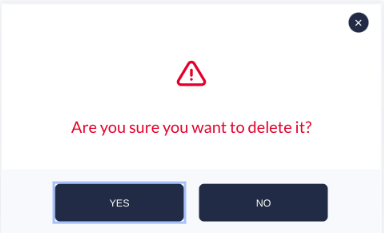
- The Delete functionality will open a confirmation window asking if the deletion is correct. Select YES to proceed or NO to cancel the action.
Figure 59: Confirmation Pop-up Window to Delete
Email Notification Management
The Email Notification Management helps users to:
- Create a Group Name with a list of the email addresses that will receive
- the notifications about the mapped work instructions.
- Manage the users’ emails that will be included in a Group Name.
- Edit or Delete Group Names that have been created previously.
Figure 60: Email Notification Management
To create a Group Name that will receive email notifications about the work instructions mapping:
- Select the ADD button to display the options.
- Then select ADD GROUP to display the Edit Notification window.
- Write the Group Name for the list of emails that will receive notifications and optionally, input the Department Name and Email.
- Select the Active option from the Email Notification field to allow that the Group Name can be selected when mapping an Added Work Instructions.
Figure 61: Edit Notification - Group Information
To edit the group information:
- Locate the cursor at the end of the row of a selected group. The Edit icon will appear to be selected.
- Select the Edit icon to open the Edit Notification window.
- Edit the information.
- Once edited, click SAVE to proceed or CANCEL to quit.
Figure 62: Edit Notification - Group Information
To delete a group:
- Locate the cursor at the end of the row of a selected group. The Delete icon will appear to be selected.
- Select the Delete icon.
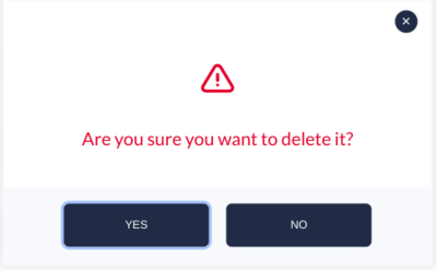
- A confirmation message will be displayed. Select YES to proceed or NO to cancel the action.
Figure 63: Confirmation Message
Note: If there are assigned users to a group, the system will prompt an alert message advising that users must be removed first before deleting the group.
Figure 64: Alert Message
To add users’ emails to a Group Name:
- Select the ADD button to display the options.
- Then select MANAGE USER to display the Manage User pop-up window.
- Select the Group Name where a new email will be added.
- Write the User Email.
- Select the Plus button. The email will appear automatically in the User List.
- SAVE to proceed or CANCEL to quit the action.
Note: Once it is successfully saved, the user list will be displayed on the User Information of the Manage User or the Group Information.
After the email has been added to a Group Name, it will appear in the User List located on the right side of the window.
Figure 65: Add Manage User
Figure 66: Add Manage User - User Information of this Group
PCB Engineering Notes
The Work Instructions tool allows the addition of PCB Engineering Notes as extra information for the mapped document, as well as to configure whether those notes will appear as default or not in the Production Workbench.
Add PCB Engineering Notes
- To create notes for any document, select the ADD NOTES button located at the right top of the screen. The Add PCB Engineering Notes pop-up window will appear asking for specific information.
- Input the information and decide whether the notes will be displayed as default or not.
- Select SAVE to create notes or CANCEL to quit.
Figure 67: PCB Engineering Notes
Figure 68: Add PCB Engineering Notes
Note: The Tool/Cam Number must be configured in the corresponding Flex Field Form (“tool_cam_number”). If this step is not completed previously, the system will prompt a message alert when clicking the Tool/Cam Number field at the Add PCB Engineering Notes window.
Figure 69: No Available Tool/Cam Found Alert Message
Edit PCB Engineering Notes
Users can edit the status of the notes or decide if they want them to display or not automatically.
To edit notes for any document from the list:
- Select the Edit icon that automatically appears when locating the cursor at the end of the selected row. The Edit PCB Engineering Notes pop-up window will appear.
- Edit the status of the engineering notes.
- Indicate if they will be displayed or not.
- Select SAVE to proceed or CANCEL to quit.
Figure 70: Edit PCB Engineering Notes
Delete PCB Engineering Notes
Users can select one, multiple, or all PCB Engineering Notes to delete them by checking the corresponding boxes.
- To delete all at the same time', check the box at the top of the list and all the boxes of the list will be ticked automatically. Todelete multiple notes, select the corresponding checkboxes of the desired notes. To delete' only one, check the corresponding box of the chosen row.
- Then, select the Delete icon. A confirmation question will be displayed in a pop-up window.
- Select YES to confirm or NO to quit.
Figure 71: Delete All PCB Engineering Notes
Figure 72: Delete Multiple PCB Engineering Notes


