42Q-MES0135-C Rapid IIoT Work Instruction
This edition applies to MES 15 Portal 1.0 and all subsequent releases and modifications until otherwise indicated in new revisions.
Contents
- 1 42Q Rapid IIoT
- 2 Introduction
- 3 Home
- 4 SPC Monitor
- 5 Measurement Configuration
- 6 Rapid IIoT Workflow
- 7 Document Revision History
42Q Rapid IIoT
42Q's Rapid IIoT solution accurately captures raw data from the shop floor (sensor devices and machinery), and inserts that data into business intelligence software, MESWeb, or 42Q SPC, where reports such as unit history, defect and repair, and SPC charts are generated for self service analytics.
Connectivity
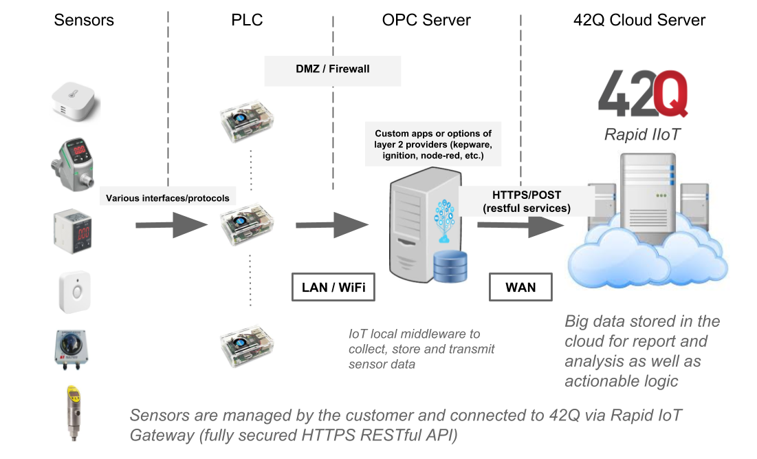
Sensor data from the Shop Floor moves to the 42Q Cloud through a designated path. The following architectural diagram illustrates the equipment and protocol used to exchange information.
42Q Rapid IIoT System Architecture Diagram
Data Applications
Rapid IIoT enables factories to quickly capture sensor data, and analyze that data to improve productivity and performance. The following sensor-related capabilities are possible through Rapid IIoT's dynamic data exchange.
- Collect sensor data from machines (e.g. temperature, pressure, tension).
- Perform SPC analytics on sensor data.
- Generate Out of Control Action Plans (OCAPs) for sensor behavior outside of lower and upper control limits.
- Compile sensor data for self-service analytics.
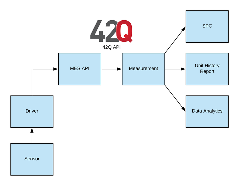
Sensor Data Flow
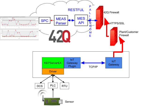
IIoT Connectivity
- Sensors capture sensitive measurement data (such as temperature, and humidity).
- Plants can use a variety of systems to release data from controlled machinery (e.g. reflow ovens).
- Some standard hardware solutions include: PLCs, DCS, and RTU (see drawing).
- Sensor data is then transferred to the system’s driver via an OPC (KepServer is one OPC software used by many manufacturers).
- OPC then sends the information to an IoT plugin that communicates with 42Q’s API.
- 42Q’s API utilizes a Measurement parser to process and store the data.
- Measurement pushes data to the data analytic tool (SPC, MESWeb, or other third party data analytic tool such as Tableau or Splunk).
- Data is analyzed by SPC and/or MESWeb, where reports are generated.
Configuration Prerequisites
In order to capture sensor data, the following items must be defined:
- A Generic Part Number (PN) See Part Number Maintenance.
- An Attribute by Process. See Attribute Definition.
- SPC Monitor (described in this document).
- Sensor Capture Measurement Parser (described in this document).
NOTE: The Process serves an important function by creating a context for the data being captured. The Process aids technical engineers and administrators in analyzing reports and diagnosing root causes. See also: SPC and Test Integration.
Introduction
This document provides complete instruction on how to configure a sensor capture parser that captures data from sensors. Instructions also include how to send that data to other systems, such as SPC or CMMS.
Home
Measurement can be accessed from the 42Q Welcome page. To log in, select a language, enter a valid screen name and password, and click the Sign In button.
Figure 1: Log In
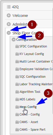
The Parser, Tooling, AutoLog Configuration, SPC Integration and Recipe Maintenance modules are located in the Shop Floor Control menu, within Meas Config. To access, navigate to: Shop Floor Control > Configuration > Meas Config.
Figure 2: Navigation
Select the Meas Config menu item to display the available modules.
Figure 3: Meas Config Modules
Note: To return to the menu of the current application suite, click the Return to Menu button.
Figure 4: Return to Menu Icon
Instance Selection
The Measurement Configuration web application is instance based. All parsers, stations, and any Measurement automated line production related information constitutes an instance and is stored in a Measurement database. Each instance is set to view one Measurement database. This produces one instance per Measurement installation. Generally, Measurement is configured to have one installation per site. It is also common to have a separate instance in the same site when there are medical operations.
To view available instances in the Measurement application, select the Instances drop down list.
Figure 5: Instance Menu Bar Location
A list of instances will display. Instances can be selected in order to update information.
Figure 6: Select a new Instance
The instance set displays as the screen’s title to help the user identify the current instance.
Figure 7: Instance in Screen Title
SPC Monitor
In order for measurement to send data to SPC, engineers must first assign an SPC monitor to receive the data. To configure an SPC Monitor:
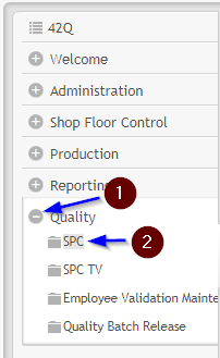
- Navigate to: Quality > Reporting > SPC.
- From the system menu, click the Expand button (+) on the left of Quality to show the menu options.
- Select the SPC icon.
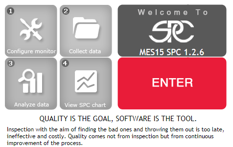
- Select Enter to access the SPC monitor list.
Figure 8: SPC Monitor Location
Figure 9: Enter SPC Portal
A list of all available Monitors displays on the SPC Home page.
Figure 10: Select Monitor Group List
Create a New Monitor
- The Function List displays in icon format.
- Select Monitor Maintenance to open a list of all Monitors available (Figure 11).
Figure 11: Select Monitor Maintenance from the Function List
Figure 12: Monitor List
- To create a new Monitor, click on the green +New icon. The following form displays:
Figure 13: New Monitor Form
Complete the Monitor Form
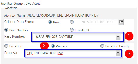
- Select a Part Number from the drop down, or type it in the Part Number field (value is case sensitive).
- Select Process.
- Select the predefined process from the drop-down menu.
- NOTE: Part Number and Process are Configuration Prerequisites.
- Important Note: To create an SPC Monitor fed from sensor data, select Manual Collection via SPC UI.
Figure 14: Manual Data Collection Strategy
- Choose an Attribute to Monitor.
- NOTE: Attributes are Configuration Prerequisites.
- Configure chart parameters as desired:
- Control Chart Type
- Chart Rules
- Notification Actions
- After all configuration fields are complete, select Save.
- The new Monitor is now available in the Monitor List and ready to receive sensor data.
Measurement Configuration
Parser
Create a New Parser
To access the Parser module from the main menu, go to: Shop Floor Control > Configuration > Meas Config and select the Parser icon.
Figure 15: Create New Parser
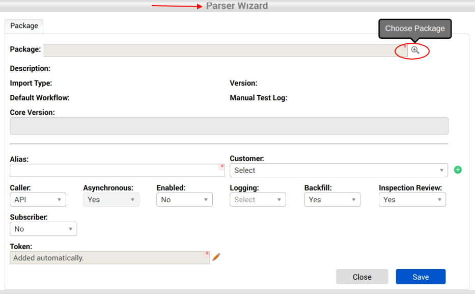
To create a new sensor capture Parser, click the green +New icon for the Parser Wizard, located at the top right of the menu bar. This action opens the Parser Wizard.
Figure 16: Parser Wizard
Figure 17: Parser Wizard
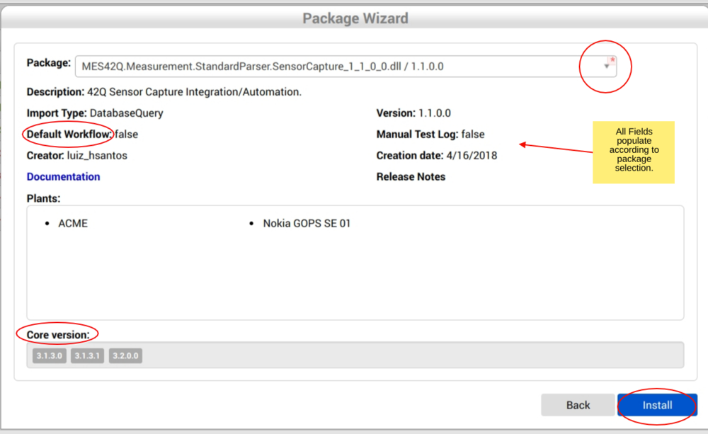
Choose & Install the Package
- Select the + icon
 to Choose and Install the Parser Package.
 - This action opens a new screen (see Figure 18, below).
- Choose the Sensor Capture Package from the drop-down menu available in the new screen.
- This action populates the remaining fields:
- Core Version: The 4-digit version from Measurement application this parser was deployed to run.
- Parser Version: 4-digit version number from this parser assembly file.
- Import Type: Informative data to identify the import mechanism the parser uses.
- Default Workflow: Technical option set by the developer to identify the parser to run in a default workflow (Import data, Parse to measurement data, send unit information to SFDC, store parametric data, release the file to out folder).
- Select Install.
Figure 18: Install Package
Package Tab Field Description
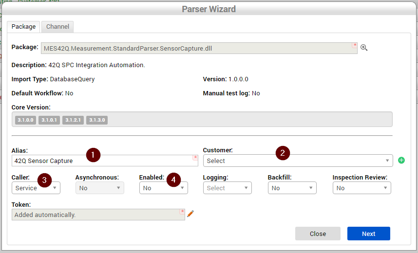
Once the package is installed, the user is redirected to the Parser configuration page (Parser Wizard) (See Figure, below). Note that the Package Field is now populated with the newly installed package and the additional Channel Tab is also available.
Package Field Descriptions are outlined as follows:
- Package: The system populates this field based on the package installed. It includes the fully qualified name from the parser file, including its extension.
- Alias: The alias identifies the parser instance. This field is automatically populated based upon the package installed. Users may optionally change the Alias by deleting the text and entering a new Alias.
- Customer: The customer whose products are processed on the automated line connected with sensor activity.
- Caller: Set how the parser will process data.
- API: Set the parser to be run from Measurement Core.
- Service: Set the Parser to be loaded from another parser.
- Asynchronous: Identify if the parser will process multiple serial number in parallel on SFDC.
- Enabled: Set the parser to run or stop.
- Logging: The user can set logging to all, info, or debug information.
- Backfill: Select whether or not to load historical data.
- Inspection Review: Toggle inspection review on or off.
- Token: A unique identifier string associated to a parser instance. This token is automatically generated.
Figure 19: Sensor Capture Parser Package
Sensor Capture Parser Field Requirements
- For Sensor Capture Parsers, the following Package Fields are required. Refer to Figure 19 (above) for Sensor Capture Configuration Example.
- Caller: Defines if this parser will be called via Service or API. For sensor capture, Select Service.
- Enabled: Defines if this parser will be initially created as enabled or not. There are more configurations to set before enabling it, it should remain No.
- Backfill: Select No.
- Inspection Review: Select No.
- Click the Next button to go to the next screen, or click Close to abandon changes.
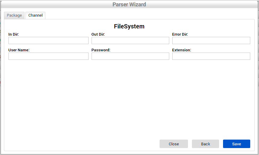
Channel Tab
- None of the fields in the Channel tab are required for Sensor Capture parser.
- Select Save to save the parser and reload the parser list screen. Select Close to abandon changes
- Select Back to return to the Package tab.
- For more details about Channel Tabs and Parser configuration, refer to Measurement/Test Integration.
Figure 20: Channel Tab
Rapid IIoT Workflow
- A parser has a well-defined workflow structure based on inbound processing and outbound information.
- Group configurations dictate where payload data will be stored & transferred.
Parser Configuration Groups
Configuration Groups allow plants to customize workflows to accommodate production line variances and technical integration requirements.
The following 4 groups must be configured for sensor parsers to capture data:
- CMMS Configuration
- Sensor Capture
- SPC Configuration
- Tag Attribute Mapping
- Select the + icon to the left of the Sensor name.
- Select the notepad icon in the Configuration Groups tab (see Figure 21, below).
Figure 21: Parser Configuration Groups
- To add a configuration to each dynamic configuration group/item, expand the group by selecting the + icon
 to the left of the group name.
Figure 22: Expand To Configure Item
Figure 23: Select Edit Icon
Figure 24: Save, Cancel, and Delete Icons
CMMS Configuration
CMMS configuration defines how the parser will send data to CMMS.
Figure 25: CMMS Configuration Group
CMMS Configuration Items
- AddDataToCMMS: Define if data will be sent to CMMS or not.
- SendAllTagsToCMMS: Define if Sensor Capture parser will send all tags received via payload to CMMS or only the ones configured in the TagAttribute item. Select False to specify a TagAttribute (see NOTE, below).
- SiteId: Site identification at CMMS.
- TagAttribute: Define which tag from the payload will be sent to CMMS. NOTE: When TagAttribute mapping is selected, SendAllTagsToCMMS value must be FALSE.
- URL: Define the CMMS URL the API will call.
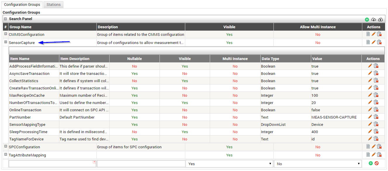
Sensor Capture Configuration
The Sensor Capture Group defines how the Sensor Capture parser handles data.
- Select Edit.
- Complete the fields per plant requirements.
Sensor Capture Configuration Items
- AddProcessFieldInformation: Defines if parser will send information to the FlexFields attached to the process or not. Select True to utilize Flex Field configuration options.
- AsyncSaveTransaction: Select True to store the transaction in parallel to the rest of the processing.
- CollectStatistics: Defines if system will collect growth statistics related to the database and transaction tables. Default value is FALSE.
- CreateRawTransactionOnLine: Defines if transactions entering via MES-API sync method (online transaction) are saved. Select TRUE to save MES-API transactions.
- MaxRecipeOnCache: Defines the Maximum number of Recipes that can be cached.
- NumberOfTransactionsToProcess: Defines the number of transactions to be retrieved for processing. Default value is 50.
- OnLineTransaction: Defines if parser will send values to CMMS and SPC synchronously or not.
- PartNumber: Defines the generic part number the parser will use.
- SensorMappingType: Defines the Tag Sensor Capture parser should look for in the station mapping configuration.
- SleepProcessingType: Defines the amount of time (milliseconds) the parser will wait to start processing the next set of data.
- TagNameForDevice: Tag name used to locate device information.
Figure 26: Sensor Capture Configuration Group
SPC Configuration
This configuration section defines how the parser integrates with the API to send data to SPC.
Figure 27: SPC Configuration Items
SPC Configuration Items
- GetAddDataToMonitor: Define the Method used to post data to a given SPC monitor.
- GetMonitorsMethod: Define the Method used to get the list of monitors available.
- SendMonitorDataInBatches: Define whether the parser will send data to monitors in batches or not.
- SPCUri: Define the Base SPC Uri.
Tag Attribute Mapping
Tag Attribute Mapping defines the relationship between tags (sent within payloads) and attributes (configured in MES). The Sensor Capture parser uses this configuration to send data to SPC.
Tag Attribute Mapping Format Requirements
Sensor data from PLCs (Programmed Logic Controls) is sent to 42Q’s API via HTTPS. During original configuration, the Measurement parser generates a token that includes the URL (instance), the process, and the software’s payload. Payload is written in JSON format Text (see below). In this way, the parser is able to locate the information according to the token, URL, and process, then send the data to 42Q’s SPC via 42Q's API.
JSON Format
{
"agent_id": "PLC_1",
"data_acquisition_ts": “123213213132” ,
"measurements": [
{
"id": "sensor_pi.office.temp",
"value": “74”,
"quality": "true",
"timestamp": "213132132132"
}
]
}
Create an Attribute Mapping
- Select AttributeMapping.
- Select Edit.
Figure 28: Create Attribute Mapping
- A new form displays: Item Name: Attribute Mapping.
Figure 29: Item Name: Attribute Mapping Form
- Complete the fields:
- Key Field: Enter the Tag Id (from the payload)
- Value Field: Enter the Attribute (from MES).
- Save.
Figure 30: Tag Attribute Mapping Configuration Example (Completed)
To further explain the movement of data, refer to the figure above. The popup shows the xml for the tag list. Note that the attributes defined in the tag are embedded in the code.
Flex Field Use Case
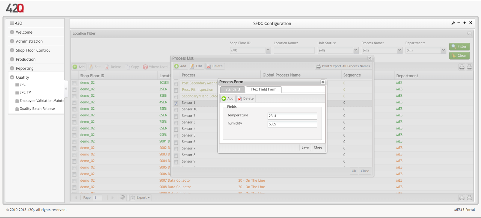
To illustrate how flex fields are applied to a factory floor, consider Shop Floor X. Shop Floor X managers need to measure two different attributes on PCBs as they exit the reflow oven: temperature and humidity. The first image (Flex Field Use Case 1) shows the last parsed values of the flex field.
Figure 31a: Flex Field Use Case 1
- Flex Field attributes are mapped to a process in MES and connected to the sensor via the attribute’s tag sent through the payload (see Flex Field Use Case 2,below).
Figure 31a: Flex Field Use Case 2
- This measurement tag shows the temperature value of 23.9 sent in the payload:
Measurement Tag
|
{ "timestamp": 1532535732707, "quality": "true", "id": "simulator.001a38000080029e.temperature", "value": 23.9 } |
- The final flex field image (Flex Field Use Case 3, below) shows all attribute/tag values sent from connected sensors on Shop Floor X.
Figure 31a: Flex Field Use Case 3
Station
The Station Mapping module links test stations to an SFDC device number and process. Within the IIoT framework, a Device is noted on the payload’s Tag. (See Tag Attribute Mapping Requirements for more details).
The Station mapping feature provides plants the ability to dynamically connect multiple customers, brands, and/or test stations to SFDC/MES locations and workstations. By placing similar data into the same subset, administrators can view overall measurement patterns to analyze and improve production.
For Sensor Capture parsers, station mapping is used to hook up data coming from specific sensors to a process, and allows measurement to send data to different SPC monitors.
Add Station
To add a new station, select the New + icon.
Figure 31: Add Station
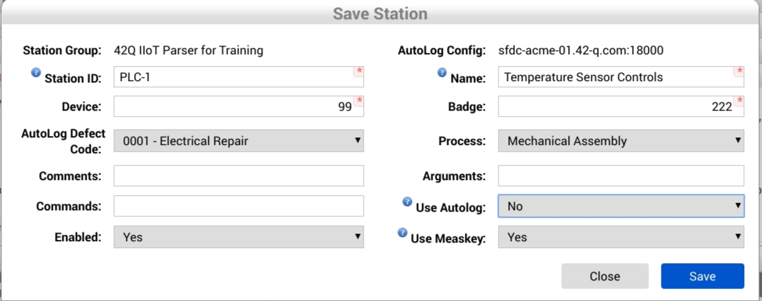
The Station Form will display.
Figure 32: Save Station Form
Station Form Fields
- Station Group: Name of the group to which the station will belong.
- *Station ID: This is the station identification. Measurement parsers use this field to match a station and device mapping from a tag in the payload sent by the sensors.
- *Device: The SFDC device number Measurement will use to communicate to SFDC when using this Station mapping.
- AutoLog Defect Code: If there is no defect mapping found for the defect being recorded, Measurement uses this default defect code on SFDC to fail a unit. This field will automatically populate.
- Comments: This is a generic field to provide additional information on the parser. Optional.
- Commands: This is a generic field to provide additional information on parser. If this sensor parser is being configured to send data to an SPC monitor, then this field must contain the monitor name the parser will send data to.
Note: Enter the exact monitor name defined in SPC: SPC_MON={spc-monitor-name}. For example: SPC_MON=MEAS_SENSOR_CAPTURE_Sensor 1_temperature
- Enabled: Set the station to be used, or not, while processing a test result data. For sensor parsers, select YES.
- AutoLog Config: The SFDC PC this parser uses to send data.
- *Name: A station name identification, like an alias, to be used on a station. .
- *Badge: The default operator to be used to login on SFDC in case this information is not provided in the test result data.
- Process: The MES process to which the test station belongs. This is used for recipe creation. It is part of the Checklist module that identifies the recipe, and sends sensor data to SPC monitors. NOTE: SPC monitors are configured in Quality > SPC.
- Arguments: This is a generic field that allows plants to pass information (arguments) from plant-specific data centers to parsers (e.g. a custom tag for a work station).
- Use Autolog: If yes is selected, the Station will not communicate with SFDC. For sensor parsers, select No.
- Use Measkey: This sets the parser to send/not send the MEASKEY command to SFDC. When set to Yes, Measurement sends the MEASKEY command to SFDC and links this MES Activity to Measurement parametric data generated by this test. Doing so makes Parametric data viewable inside the Unit History report on MESWeb. For Sensor Parsers, select No.
- Fill out all mandatory fields (denoted with*).
- Select Save.
- Measurement will validate the data and insert the new station into the group.
- The new station is now available in the station list (see Figure, below).
Figure 33: Newly Configured Work Station
Document Revision History
| Date | Author | Title | Version | Approved by |
| 05/11/18 | Luiz Santos/Martha Jordan | Development Supervisor/Technical Writer | A | This is the first version of Rapid IIoT. |
| 07/31/18 | Martha Jordan/Lucas Hopkins/Disha Sharma | Technical Writer/Business Analyst | A1 | Add use case. Remove screenshot. Add field details. |

