SOP-42Q-MES0012 Product Route Maintenance
42Q Home > Shop Floor Control > Configuration > Product Route Maintenance

This edition applies to MES15 Portal 1.0 Application and all subsequent releases and modifications until otherwise indicated in new revisions.
Contents
- 1 SFDC Configuration Setup
- 2 Product Route Maintenance
- 3 Appendix A
- 4 Document Revision History
SFDC Configuration Setup
42Q’s powerful data collection system collects critical information from a plant’s shop floor, utilizing shop floor data collector, an intuitive tool developed by 42Q’s experienced manufacturing team. The aggregate information is stored in a cloud database, and available to MESWeb, where quality reports are generated. The 42Q system uses manual and automated barcode scanning to collect data for a product line or plant. Thus, 42Q plays an important role in maintaining unit histories and directing product movement on the manufacturing floor. The current version of 42Q includes configuration capabilities, which provide access to all sub-modules pages and their functionalities (view, add, edit, print/generate output files).
NOTE: A user only has access to the
Product Route Maintenance
A route is the sequence of steps that a product follows to complete the manufacturing process. A route also controls rework requirements. The Product Routing Manager creates, views, and updates Route definitions. SFDC assigns every product to a route. The route should be flow-charted as a reference for the actual process prior to creating the route definition.
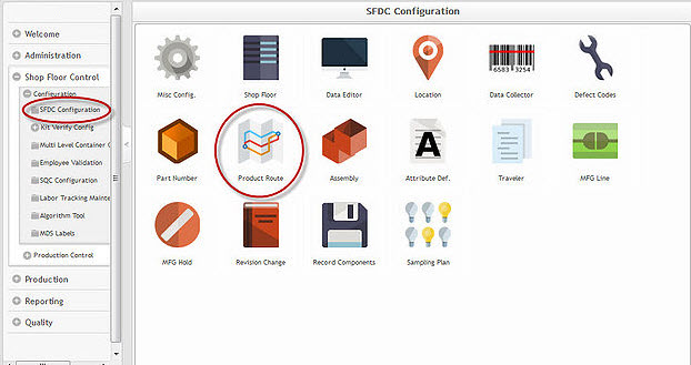
1. To access Product Route Maintenance, navigate to Shop Floor Control>Configuration>SFDC Configuration>Product Route.
Figure 1: SFDC Configuration Main Page
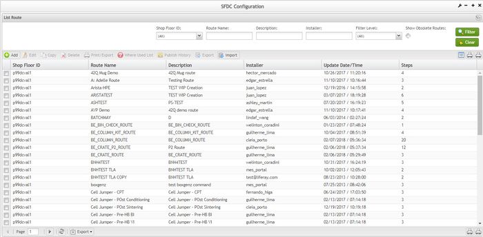
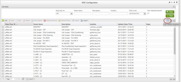
Figure 2: List Route
2. From this page, the user is able to execute the following actions:
- Edit
- Copy
- Delete
- Print/Export
- Where Used List
- Print/Export Filtered
- Export All Installed Steps
- Part X Routes Assignments
The user is able to use the pagination feature to navigate between the Product Route pages.
Route Naming Conventions
As a general rule, route names should be prefaced with a character and a colon ":" to easily identify the type of route, as well as simplify sorting and/or filtering. The route type would depend on its intended use. For example, Product Specific, Generic/General Shared, Subroute, and Master Subroute.
Product Specific Routes are assigned only to a single product or part number. The route name will begin with "P: " (for Product) identifying it as a product specific route.
Product Specific Route Examples:
P:VALBB_TCOMP
If multiple routes are to be created for the same part number, add a -A, -B (or -1, -2) suffix to the end of the Route Name.
Multiple Product Specific Route Examples:
P:LF563-041-A
P:LF563-041-B
P:LF563-041-C
Generic/General Shared Product Routes are assigned to multiple products or product lines, or family. The route name will begin with “G:” (for Generic or General) identifying it as a generic/general shared route. When using a part number as part of the route name, use the standard masking format (a for letters, and n for numbers) where necessary.
Generic Shared Product Route Examples:
G:GE1006711-9m
G:GE1006712-9m
Subroutes are used in multiple product specific, or generic/general shared routes. The route name will begin with “S:” identifying it as a subroute.
Standard Subroute Example:
S: AUDT-SHIP-SUBVC
S: AUDT-CMP1
Above identifies a subroute with definite 'from' and 'pass' locations.
Subroute Exit Example:
S: ADT1 – (?)
S: AXI1 – (?)
Above identifies a subroute as a subroute exit. The 'pass to' location, denoted by the “(?)” is defined in the product route.
Subroute Entry Example:
S: (?) – PURG
S: (?) - OBAT
Above identifies a subroute as a subroute entry. The 'from' location, denoted by the “(?)” is defined in the product route.
Master Subroutes are Subroutes that are used in all (or many) P: Part_Number or G: Generic_Route routes. Master Subroutes provide an easy way of adding/modifying routes (mass rework, scrap, evaluation, etc.) that affect every part number. The route name will begin with “M: ” identifying it as a master subroute.
Master Subroute Example:
M: Master – MFG
M: Master - RMA
Filter Routes
This functionality enables the user to search for a specific route from all available routes.
To perform the filter search, populate the desired filter fields then select Filter.
Select Clear to clear the filter fields.
Figure 3: List Route – Filter/Clear routes
Add Route
This functionality enables the user to add a new route to the database.
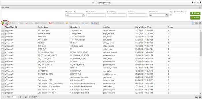
To add a route, select the Add icon located in the List Route main screen. The Route form is displayed:
Figure 4: Add Route
1. Select the desired Shop Floor ID from the drop-down list.
2. Enter the Route Name.
As a general rule, it is preferred that the aforementioned Route Naming Conventions be used when naming routes.
3. Enter a brief route Description.
NOTE: This is a user defined field. It is often useful to describe the route in this field.
4. The Route Step formis displayed.
Figure 5: Route Step page
SOP-5-I-MDS0040- RA1 MDS Product Route Maintenance WIKI 05.png
There are four different route options used to create routes: Standard, Inserted Subroute, Subroute Entry and Subroute Exit.
Start defines the status of each Route step. Select Yes if any of the following conditions exist:
- The product is scanned for the first time and the serial record is being created.
- The product has a serial record created, released on a Shop Order, and is scanned for the first time at the location specified as a start step.
- The product is associated with another Route (same or different SFDC ID) and is scanned for the first time as a step in this Route. The product must be in an Online Hold or In Repair Hold location and be listed as a ’from location for the start step location.
Standard Route Option
The standard route option is the most basic of all route types. The steps need to be defined with each new route created. The configuration of a Standard Route Option can be completely unique to this route.
As a general rule, when a commonly used route step configuration is desired, utilizing Subroute type Options is preferred. These route options allow the user to avoid having to reconfigure the same Location multiple times for each new route, which is the case when using the Standard Route Option. The Subroute Option provides an extremely fast means for updating multiple product routes that call the subroute. The user is only required to update one route; therefore any/all routes calling the subroute will follow its Route Step configuration. Subroutes are called by selecting Inserted Subroute Option when creating the route.
Figure 6: Route Step - Standard
1. Select the Step number, then the Standard option, and check Start? if the step is a start location.
NOTE: The Step number is used for ordering the route steps.
As a general rule, configure each Route Step in chronological order with the process flow of the product.
2. Enter, or select from the drop-down menu, the desired Location name.
Location: Defines the Location in the assembly process where the product is scanned. The location must be unique from all other Locations within the Route, including subroutes.
NOTE: Only locations associated to the selected SFDC ID are displayed.
3. Enter, or select from the drop-down menu, the desired Pass Location.
Pass: Defines the pass location in the assembly process. This Location should be a Logical Location with an On the Line status. This allows multiple Locations with the same Process name to pass to a common holding area for the next Location in the Route. It is mandatory to select the Pass step.
NOTE: Only On the Line status locations associated to the SFDC ID are displayed.
4. Enter, or select from the drop-down menu, the desired Fail Location.
Fail: Defines the fail location in the assembly process. This Location should be a Logical Location with an In Repair status.
NOTE: Only In Repair status locations associated to the SFDC ID selected in the previous Route are displayed.
5. Enter, or select from the drop-down menu, the desired SFDC ID and Src. Loc. 1: (Source, or 'from ’
Location) Up to four Source Locations may be defined for a single route step.
Source Locations: define the Location from which a unit is accepted. If a unit is at any Location other than one of the four listed, a Flow Error occurs and the product is not accepted. This Location is one of the Logical Locations used as a pass or fail in any of the previous steps. Unless this route step has a Start status, at least one from Location should be selected. If no Source Location is defined, and it is not a Start Step, the route step location is able to accept units from any location on the same SFDC ID. Caution should be taken when leaving the Source Locations blank as the flow of control provided by the route is compromised. Leaving Source Locations blank is not a preferred routing strategy in most production location steps.
By default, the SFDC ID selected in the first step is displayed. The user may select any SFDC ID and Location desired. If selecting a SFDC ID other than the one selected in the first step, keep in mind that this route step must be a Start step and the location selected as the Source Location on the other SFDC ID must be status On the Line Hold or In Repair Hold.
NOTE: As a general rule, the Source Location 1 is defined as the same location selected for the Route Step. The scan location must always accept from itself to avoid Flow Error.
6. Check the Add More? check-box to insert additional route steps, or remove the check if this is the last Route Step to be defined for this route.
NOTE: If Add More? Check-box was checked, the user is able to define another Route Step.
The route step list is displayed. If no update is necessary, select Save. A confirmation message is displayed.
Figure 7: Install Route
Subroute Entry Route Option
The Subroute options indicate that a route step will be configured separately from a product route and will be called by another route (using the Inserted Subroute option). When a Subroute option is selected, all input fields except for the required input fields are disabled. The Subroute Entry Route Option indicates the step is an entry for the subroute used by another route. All source locations are disabled and the route calling the Subroute will provide the Source Locations.
As a general rule, when a commonly used route step configuration is desired, utilizing Subroute type Options is preferred. These route Options avoid having to reconfigure the same Location steps over and over again, with each new route, which is the case when using the Standard Route Option. The Subroute Option provides rapid means for updating multiple product routes that call the subroute. The user is only required to update one route; therefore any route calling the subroute will follow its Route Step configuration. Subroutes are called by selecting Inserted Subroute Option when creating the route.
Figure 8: Subroute Entry
1. Select the Step number, then select Subroute Entry, and check the Start? check-box if the step will be a start location.
NOTE: The Step number is used for ordering the route steps.
As a general rule, configure each Route Step in chronological order with the process flow of the product.
2. Enter, or select from the drop-down menu, the desired Location name.
Location: Defines the Location in the assembly process where the product is scanned. The location must be unique from all other Locations within the Route, including subroutes.
NOTE: Only locations associated to the selected SFDC ID are displayed.
3. Enter, or select from the drop-down menu, the desired Pass Location.
Pass: Defines the pass location in the assembly process. This Location should be a Logical Location with an On the Line status. This allows multiple Locations with the same Process name to pass to a common holding area for the next Location in the Route. It is mandatory to select the Pass step.
NOTE: Only On the Line status locations associated to the SFDC ID selected are displayed.
4. Enter, or select from the drop-down menu, the desired Fail Location.
Fail: Defines the fail location in the assembly process. This Location should be a Logical Location with an In Repair status.
NOTE: Only In Repair status locations associated to the SFDC ID selected are displayed.
5. The Source Locations are disabled because the route calling the Subroute will provide the Source Locations when configuring the Inserted Subroute Option.
6. Check the Add More? Check-box to insert additional route steps, else remove the check if this is the last Route Step to be defined for this route.
7. Click Save to proceed to the Route Step List page.
Subroute Exit Route Option
The Subroute options indicate that a route step will be configured separately from a product route and will be called by another route (using the Inserted Subroute option). When a Subroute option is selected, all input fields except for the required input fields are disabled. The Subroute Exit Route Option indicates the step is an exit for the subroute used by another route. The Pass Location is disabled because the route calling the Subroute will provide the Pass Locations.
As a general rule, when a commonly used route step configuration is desired, utilizing Subroute type Options is preferred. These route Options avoid having to reconfigure the same Location steps over and over again, with each new route, which is the case when using the Standard Route Option. The Subroute Option provides an extremely fast method for updating multiple product routes that call the subroute. The user is only required to update one route; therefore any route calling the subroute will follow its Route Step configuration.
Figure 9: Setup the Option and the Step Number
1. Select the Step number, then select Subroute Exit, and check the Start? check-box if the step is a start location.
NOTE: The Step number is used for ordering the route steps.
As a general rule, configure each Route Step in chronological order with the process flow of the product.
2. Enter, or select from the drop-down menu, the desired Location name.
Location: Defines the Location in the assembly process where the product is scanned. The location must be unique from all other Locations within the Route, including subroutes.
NOTE: Only locations assigned to the selected SFDC ID are displayed.
3. Pass location is disabled because the route calling the Subroute will provide the pass locations when configuring the Inserted Subroute Option.
4. Enter, or select from the drop-down menu, the desired Fail Location.
Fail: Defines the fail location in the assembly process. This Location should be a Logical Location with an In Repair status.
NOTE: Only In Repair status locations associated to the selected SFDC ID are displayed.
5. Enter, or select from the drop-down menu, the desired SFDC ID and Src. Loc. 1: (Source, or ’
from ’
Location) Up to four Source Locations may be defined for a single route step.
Source Locations define the Location from which a unit is accepted. If a unit is at any Location other than one of the four listed, a Flow Error occurs and the product is not accepted. This Location is one of the Logical Locations used as a pass or fail in any of the previous steps. Unless this route step has a Start status, at least one from location should be selected. If no Source Location is defined, and it is not a Start Step, the route step location is able to accept units from any location on the same SFDC ID. Caution should be taken when leaving the Source Locations blank as the flow of control provided by the route is compromised. Leaving Source Locations blank is not a preferred routing strategy in most production location steps.
By default, the SFDC ID selected is displayed. The user may select any SFDC ID and Location desired. If selecting a SFDC ID other than the one selected in the first step, keep in mind that this route step must be a Start step and the location selected as the Source Location on the other SFDC ID must be status On the Line Hold, or In Repair Hold.
NOTE: As a general rule, the Source Location 1 is defined as the same location selected for the Route Step, which is itself. The scan location must always accept from itself to avoid Flow Error.
6. Check the Add More? check-box to insert additional route steps, else remove the check if this is the last Route Step to be defined for this route.
NOTE: If Add More? Check-box was checked, the user is returned to define another Route Step.
7. Select Save to proceed to the Route Step List page.
Inserted Subroute Option
The Subroute options indicate that a route step will be configured separately from a product route and will be called by another route (using the Inserted Subroute option). When the Inserted Subroute Option is selected, all input fields except for the required input fields are disabled. The Inserted Subroute Option indicates the step will insert a previously created subroute. The required input fields are displayed as required, depending on the route type option selected.
The following conditions are implied when inserting subroutes:
- If a Standard Subroute is selected, no other input field is required.
- If a Subentry Subroute is selected, only the Source Locations will be required.
- If a Subexit Subroute is selected, only the Pass Location will be required.
As a general rule, when a commonly used route step configuration is desired, utilizing Subroute type Options is preferred. These route Options avoid having to reconfigure the same Location steps over and over again, with each new route, which is the case when using the Standard Route Option. The Subroute Option provides an extremely fast method for updating multiple product routes that call the subroute. The user is only required to update one route; therefore any/all routes calling the subroute will follow its Route Step configuration.
Figure 10: Inserted Subroute Option
1. Select the Step number, then select Inserted Subroute, and un-check the Start? check-box.
NOTE: The Step number is used for ordering the route steps.
As a general rule, configure each Route Step in chronological order with the process flow of the product. Inserted Subroute Options are rarely flagged as Start status as this should be defined in the subroute.
2. Enter, or select from the drop-down menu, the desired Subroute name.
NOTE: Only Subentry and Subexit Subroutes associated to the selected SFDC IS are displayed.
If the standard route naming convention was followed, the user can type the Subroute prefix (S:) to retrieve the desired subroute names.
3. Check the Add More? check-box to insert additional route steps, else remove the check if this is the last Route Step to be defined for this route.
4. Select Save to proceed to the Route Step List page.
Edit Route
This functionality enables the user to edit any of the available fields to update a Route.
NOTE: Fifty-five minutes after the Route has been opened for Edit, the system warns the user that the edit time will expire. Five minutes after the warning, the route update page is closed and the user is redirected to the main route list.
MES does not allow editing a Route at the same time by two different users. If a Route is being edited by one user and another user opens the route, a message is displayed stating the route is locked for editing and is read-only.
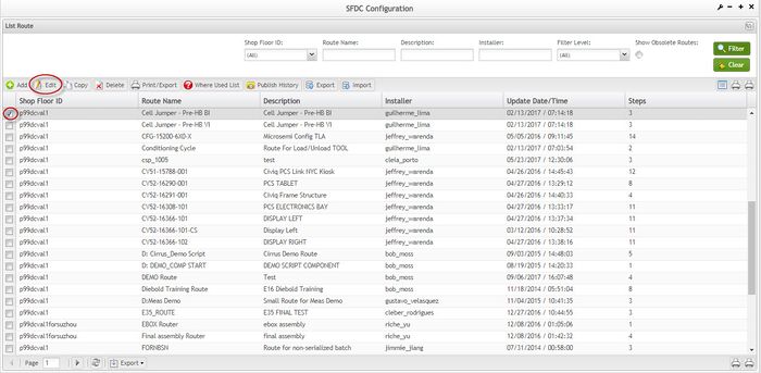
1. To edit a route, select the Route to be updated then select Edit from the List Route main screen.
Figure 11: List Route - Edit Route
The Route Step List is displayed:
Figure 12: Route Step List
The route information contains Route Name, Description, SFDC ID, Update Date/Time, Steps and the Installer.
The colors in the tree depend on the Location status.
Add Route Step
This functionality enables the user to add a route step to the selected Route.
1. To add a route step, select the Add icon.
The Route Step Configuration form is displayed:
Figure 13: Add Route Step
2. Reference section Add Route for additional details, as this is the same process (with the exception of selecting the SFDC ID, creating the Route Name, and Description, as these tasks only occur when creating a new route).
Edit Route Information
This functionality enables the user to edit the Route Name and Description.
1. To edit Route Information, select the main Route Name from the display window, and then select Edit.
2. The Route Information page is displayed:
Figure 14: Edit Route
3. Make the necessary updates and click on Save.
As a general rule, it is preferred that the Route Naming Conventions be used when naming routes.
Edit Steps of Route
This functionality enables the user to modify any of the available fields to update a step route.
1. To edit a step route, first select the step to be edited, and then select Edit.
The Route Step Information window displays.
Figure 15: Route Step List
The route step information contains Step, Option (Standard, SubEntry, SubExit and SubRt – Inserted Subroute), Location, Subroute, Pass and Fail (next step options), Source Locations and Is Start (true or false).
From the Route Step List, the user can perform the following operations for the selected Step:
- Add
- Edit Steps information
- Copy Steps
- Delete Steps
- Change Step Number
Edit Step Information
This functionality enables the user to edit Route step information.
NOTE: It is not possible to edit an Inserted Subroute. These subroutes must be modified as a Local Route separately.
1. To edit step information, select the desired step and then select Edit.
Figure 16: Route Step Information
2. Make the necessary updates to the Route Step.
NOTE: Location is mandatory in this example, though this will not always be the case. This is the case when editing a step that contains an Option of SubRt. As the Option is changed, the required fields are enabled for editing. If a mandatory field is missing information, a warning message is displayed.
3. Select Next to confirm modifications.
Copy Route Step
This functionality enables the user to copy Route Steps from one selected step to another.
1. To copy a route step, select the desired step to copy and then select Copy.
The Route Step page is displayed:
Figure 17: Copy Route Step
2. Enter the desired Step#.
If the entered Step# already exists in the route, a confirmation message is displayed stating the step number already exists and prompts to overwrite the existing step.
NOTE: the Step number is used for ordering route steps.
As a general rule, configure each Route Step in chronological order with the process flow of the product.
3. Select Save to continue.
A "Successful" message is displayed to the user.
Select Save to install the route.
Delete Route Step
This functionality enables the user to delete a selected Step.
1. To delete a route step, select the desired step to delete and then select the Delete icon.
Figure 18: Delete a Route Step
A confirmation message is displayed.
Select Save to install the route or Reset to return.
Change Route Step Number
This functionality enables the user to change a Route Step Number. The new Step Number must be unique as duplicates are not allowed.
1. To change route step number, select the desired step and then select Change Step Number.
The Change Step Number popup is displayed:
Figure 19: Changing Step Number
2. Enter the desired Step#.
If the entered Step# already exists in the route, an error message is displayed stating the step number already exists. Select Ok to return to the Change Step Number window and re-enter unique step number.
NOTE: the Step number is used for ordering route steps.
As a general rule, configure each Route Step in chronological order with the process flow of the product.
3. Select Save to continue.
4. Select Save again to install the route.
Delete Unused Routes
This functionality enables the user to delete unused routes. It might be utilized when routes for obsolete products are no longer needed.
Prior to deleting a route the following must be taken into consideration:
- Caution should be used when deleting routes, as the route is removed from the local database. If there is a reason the route needs to be restored, the plant is required to submit a Work Request to have SFDC group restore the route.
- There may not be any serial numbers associated to the route in WIP. A validation is performed on WIP to insure that there is not any unit with a status less than 30 attached to the route to be deleted. If there is, a dialog box is displayed stating there is a unit attached to the routing that must first be completed before the route can be deleted.
- There Setup Editor may not contain any active references to the route to be deleted. If references are found, an MDS Error box notifies the user that the route is unable to be deleted as it is referenced in the displayed Shop Floor IDs. Any/all references to the route must first be removed from the Setup Editor prior to deletion.
- The system will remove any Part x Route Assignments associated with the route upon deletion.
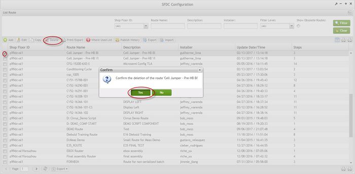
1. To delete an unused route, select the desired route to be deleted and then select Delete.
A confirmation window is displayed:
Figure 20: List Route – Delete Unused Route
2. Select Yes to confirm or No to cancel
3. The route is deleted from the database.
Copy Routes
This functionality enables the user to copy an existing route. This may be useful when replicating a complex route that may require little or no modifications. All Route information is copied to the new Route Name.
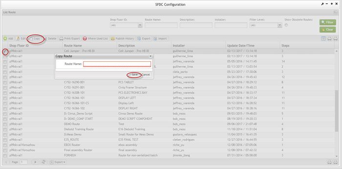
1. To copy a Route, select the desired Route to copy and then select Copy.
The Copy Route popup is displayed:
Figure 21: List Route - Copy
2. Enter the desired Route Name.
As a general rule, it is preferred that the Route Naming Conventions used when naming routes.
3. Select Save to confirm or Cancel to cancel route copy.
4. The original selected route has been copied and added to the database under the new route name.
Print/Export Individual Route
This functionality prints the steps of a Route selected from the Routes List. The report results include all Route Information. The report prints to the default printer for the workstation.
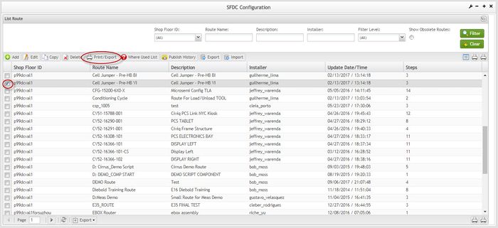
1. To print/export an individual route, select the desired route and then select Print/Export.
Figure 22: List Route – Print/Export
2. A report is generated and the user is able to save the file or print it.
Figure 23: Generated report
Print/Export Filtered Routes
This functionality enables the user to print or export filtered routes.
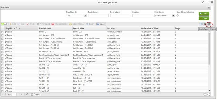
1. To print filtered Routes, select Print Filtered Routes from the List Route main screen.
Figure 24: Print Filtered Routes
A report is generated and the user is able to save the file or print it:
Figure 25: Generated report
Print/Export All Installed Steps
This functionality enables the user to print or export all Installed Steps.
1. To print all installed steps, select Print All Installed Steps from the List Route main screen.
Figure 26: Print All Installed Steps
A report is generated and the user is able to save it locally.
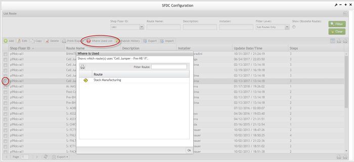
Where Used List
This functionality is enabled when the selected route is a subroute.
Select the route and then select Where Used List.
Figure 27: Where Used List
In this sample it is possible to know that the selected route is used as a subroute of PF: TESTTLAPNxx.
Publish History
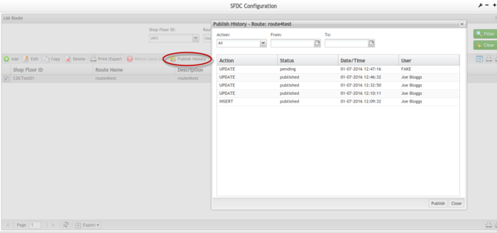
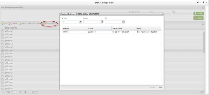
The Publish History functionality is used by permitted users to show and publish the action history of a Route. To use this functionality
- Select a route from the list. The Publish History function becomes available for selection.
- Select Publish History. The Publish History window pops up for the given route. This history shows the Action, Status, Time/Date, and User for each item.
- Select Publish, to publish the history to Conduit. Select Close to end or abort.
NOTE: The Publish History Conduit functionality is also available under Part x Route Assignment. The functionality is used the same way as described for List Route.
Figure 28: Publish History
Part x Route Assignment
This functionality enables the user to view the Part Route Assignments.
All part numbers require a Part x Route Assignment to follow the production process flow defined in the Route. The exception to the addition of a Part x Route Assignment is when the assignment statement is added to the Setup Editor. i.e. NAME PRODUCT=(part mask) ROUTE=(route name)
1. To assign a part to a route, select Part x Route Assignment from the List Route main screen.
Figure 29: Add Part X Route Assignment
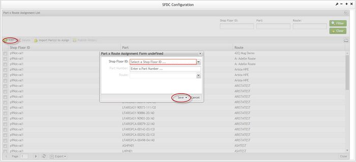
Figure 30: Add Part x Route Assignment (from Part x Route Assignment List page)
1. Select the desired SFDC ID;
2. Enter the Part Number;
3. Select the Route.
4. Select Save to commit the addition or Cancel to cancel the action.
5. A successful message displays.
6. The new assignment is displayed at Part / Route Assignment List.
From this page the user is able to Add Part x Route Assignment, Import Part(s) to Assign, Print/Export Filtered Part x Routes as well as Delete part to Route Assignments.
Delete Assignment
This functionality enables the user to delete the selected Part x Route Assignment.
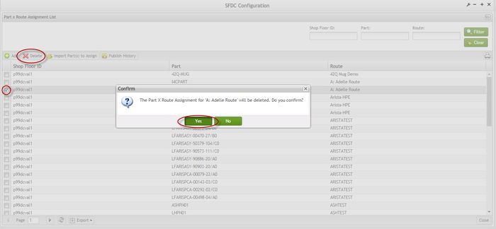
1. To delete a Part x Route Assignment, select the desired part x route assignment and then select Delete.
Figure 31: Part x Route Assignment List - Delete
2. A confirmation window is displayed;
3. Select Yes to confirm or No to cancel.
4. The selected Part x Route Assignment has been deleted from the database.
Print/Export Filtered Part x Route
This functionality enables the user to print or export the filtered Part/Route Assignment List.
1. To print assignments, select Print from the Part x Route Assignment List screen.
Figure 32: Print/Export Filtered Part x Routes
A .PDF report is generated:
Figure 33: Print/Export Filtered Part x Routes Report
Import Part(s) to Assign
This functionality enables the user to import a list of part numbers to assign to a single Route. The import requires the part numbers be defined in a comma separated value (CSV) file that has been exported from the Part Maintenance module.
1. Save the CSV file at a known location. This file will be imported in step 4.
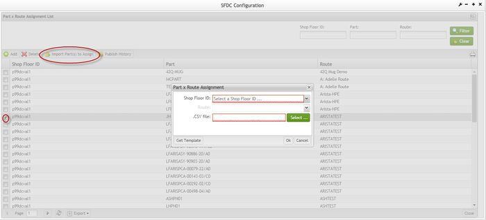
2. To import part(s) to assign to a route, select Import Part(s) to Assign.
3. The Part x Route Assignment importpage is displayed:
Figure 34: Import Part(s) to Assign
4. Select the SFDC ID from the drop-down list.
5. Select the Route from the drop-down list.
6. Select Ok to import or Cancel to cancel import.
The Assigning Results confirmation page is displayed:
Figure 35: Part x Route Assignment Import Result
SOP-5-I-MES0012-C RA1 ProdRoute35A.jpg
Publish Histpry
The Publish History functionality is used by permitted users to show and publish the action history of a Route. To use this functionality.
Figure 36: Publish History
For further information, please see Publish History topic on page 29.
Appendix A
Glossary
Access Control
A module that will set the permissions for users and external customers of 42Q
Administrator
The System Administration has full access - all plants, all reports, all users.
Component
A component is a specific piece of data that appears on a label, for example: bar code, part numbers, graphic images, line or text. Hence, label components are broken down into several different types: text, graphic images, MDS database values, or a combination of text and database values.
Framework
In software development, a framework is a defined support structure in which another software project can be organized and developed. A framework may include support programs, code libraries, a scripting language, or other software to help develop and glue together the different components of a software project.
SFDC Configuration
The rules used to define how SFDC collects data, provides analysis, controls processing and maintains unit histories
Site Minder
Universal login of 42Q
Username
The username is the siteminder username (or a partial string)
Document Revision History
| Date | Author | Title | Version | Change Reference | Approved by |
| 09/09/13 | Elaine Fonaro | Technical Writer | v 1.0 | This is the first revision of MDS User ’s Guide | |
| 02/10/14 | Ashley Martin | Technical Writer | v 1.0 | Grammar and images review | |
| 02/12/14 | Elaine Fonaro | Technical Writer | v 1.0 | Formatting | |
| 01/21/16 | Dane Parker | Technical Writer | v 1.0 | Added Conduit functionality | |
| 04/26/16 | Elaine Fonaro | Technical Writer | v 1.0 | Converted to 42-Q | |
| 07/21/16 | Molly Kits | Technical Writer | Converted to Google Docs | ||
| 10/07/16 | Benjamin Cavanaugh | Technical Writer | v 1.0 | Minor formatting changes | |
| 04/3/17 | Martha Jordan | Technical Writer | v 1.0 | Rewrite SFDC introductory paragraph according to current 42Q functionality | Bob Moss |
| 08/02/17 | Lucas Hopkins | Technical Writer | v 1.0 | Minor grammatical and formatting edits | |
| 02/08/2018 | Elaine Fonaro | Thecnical Writer | v 1.0 | Updating Images 2,3,4,11,20,21,22,24,27,29,30,31,34 and 36 to reflect the Pagination and Publish History features. |
