SOP-42Q-MES0005 Data Editor Maintenance
Cirrus > Shop Floor Control > Configuration > Data Editor Maintenance

This edition applies to MES15 portal V1.0 and all subsequent releases and modifications until otherwise indicated in new revisions.
SFDC Configuration Setup
This edition applies to MES 15 Portal 1.0 and all subsequent releases and modifications until otherwise indicated in new revisions.
The Shop Floor Data Collection (SFDC) system communicates interactively with the Customer Order Processing System (COPS), and Statistical Process Control/Statistical Quality Control (SPC/SQC). The Manufacturing Data System (MDS) makes the communication between these systems possible.
SFDC provides real-time information used by SPC/SQC and MESWeb to create quality control reports. The data configuration for SFDC PC is handled within the Manufacturing Data System (MDS), which is a complete factory automation system. The SFDC System uses bar-code scanning, both manual and automated, to monitor and control a single product line or an entire plant. SFDC Configuration collects data, provides analysis, maintains unit histories, and controls product movement on the manufacturing floor.
The system provides Access Control between the modules of the application, including the portlet of each screen. The current SFDC Configuration page provides access to all sub modules pages and their functions (view, add, edit, delete, print and generate output file).
SFDC Configuration
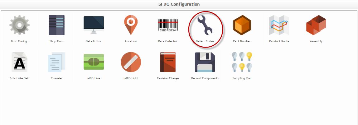
1. To access SFDC Configuration, navigate to Shop Floor Control > Configuration > SFDC Configuration. The main SFDC Configuration page is displayed:
Figure 1: MES Portal – SFDC Configuration Sub-modules
NOTE: A user only has access to the modules assigned to his/her profile.
Defect Codes Maintenance
Defect and Repair Codes are maintained through Defect Codes Maintenance from the SFDC Configuration Maintenance module.
This module allows defects found after a component is manufactured to be recorded. According to the number of records, the operator will be able to identify a defect to a specific component and reference that defect in the future.
List Defect Codes
To list Defect Codes, click on Defect Codes Maintenance in the SFDC Configuration menu.
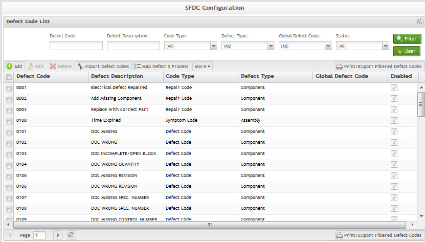
The list of defect codes is displayed:
Figure 2: Defect Code List
The user is able to Add, Import, Print/Export, Edit and Delete Defect Codes.
- Defect Codes beginning with ’B’ are displayed in blue.
These codes are known as Process Indicator defects. Process Indicator codes do NOT negatively affect process yield. A process indicator is only used to document a marginal attribute to indicate that it was noted, reviewed and found to be acceptable by the reviewer. Documentation of process indicators provides a measure of the frequency of marginal attributes.
- Defect Codes beginning with "K" are displayed in green.
- All other Defect Codes are displayed in black.
Note: All defect codes that begin with the letter B are called process indicators. They are unique in that they will not impact yield and they will not trigger a failure in SFDC. Any defect code that begins with K is a standard defect code, which will result in a failure and impact the yield. B defect codes are used to indicate the current condition of a process.
Add Defect Code
This functionality adds a defect code in the system.
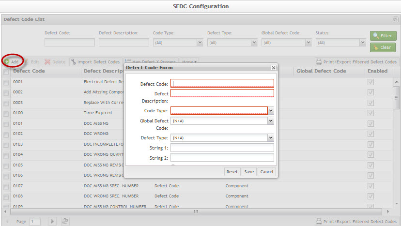
1. To add a Defect Code, click the Add button. The Defect Code Form is displayed:
Figure 3: Add Defect Code
2. Populate the mandatory fields (indicated in red) to add a Defect Code. If the mandatory fields are not populated, an error message displays.
Defect Code: must be four unique characters
As a general rule:
- Defect Codes that begin with "B" represent Process Indicators. For example: B174 Probe Mark
Process Indicator codes do NOT negatively affect process yield. A process indicator is only used to document a marginal attribute to indicate that it was noted, reviewed, and found to be acceptable by the reviewer. Documentation of process indicators provides a measure of the frequency of marginal attributes.
- Defect Codes that begin with "K" represent Symptom Codes. For example: K001 Boot Strap Failure. Symptom Codes define the symptom of the failure, not an actual defect. Symptom Code defects negatively affect process yield the same as all other defects.
- Defect Codes that begin with "R" represent Repair Codes. For example: R001 Replaced Missing Components. Repair Codes are used to indicate specific repair activity for a recorded defect. For example, the Repair Code for the "Missing" defect code may be "Replaced Missing Components". The four character Repair Code is used in place of "Yes" and/or "No" for defect repair activity.
Defect Description: Intuitive Description of the defect, limited to 30 characters
String 1 and String 2: Editable user-defined fields
Code Type: Defect Code, Repair Code, or Symptom Code
NOTE: Align the Code Type with the Defect Code formatting discussed above.
3. Select Save to add Defect Code, or select Cancel to cancel. The new Defect Code list is now displayed in the defect list.
Edit Defect Code
This functionality enables the user to edit the available fields to update a Defect Code.
Note: Be aware that modifying Defect Codes will affect the historical defect information for any serial number with the defect recorded. Take care when editing to avoid changing the code description in such a way that it is completely different than the original. It is best to create a new Defect Code in this situation.
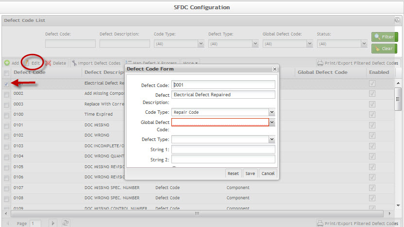
1. To edit a defect code, select a defect and click the Edit button. The Defect Code Form page is displayed.
Figure 4: Edit Defect Code
2. Make desired updates in the Defect Code Form and click on Save to confirm the updates.
Delete Defect Code
This functionality deletes the selected Defect Code.
NOTE: It is not possible to delete Defect Codes that have activity recorded.
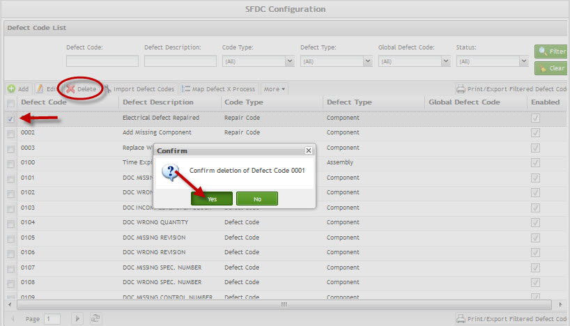
1. To delete a Defect Code, select the Delete button for desired defect code. A confirmation message is displayed.
Figure 5: Delete Defect Code
2. Select Yes to confirm the deletion action, or select No to cancel the action.
Map Defect X Process
This functionality maps defect codes by processes. By mapping defect codes according to processes, the selection of defect codes, repair codes, and symptom codes can be controlled. If defect codes are not mapped to a process, all defect codes will be available to the user.
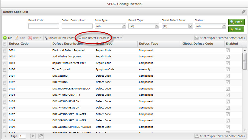
1. To access Map Defect Codes by Process, select the button located above the Defect Code list.
Figure 6: Map Defect X Process
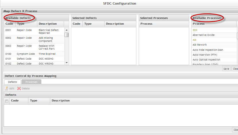
The Defect X Process screen displays. In the panel on the left, all available defects are listed. In the panel on the right, all available processes are listed. The center columns are empty until defects and/or processes are selected and moved into them.
Figure 7: Available Defects/Processes
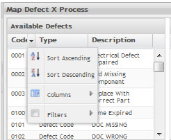
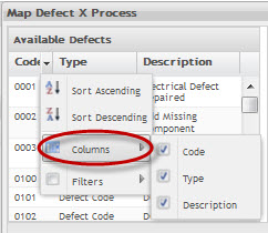
For each column in the panels, sorting and filtering options are available.
Figure 8: Sorting/Filtering Options
Columns and Filters have sub-selections available.
Figure 9: Filter Columns
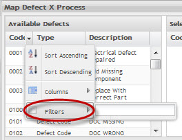
Columns can be filtered by Code, Type, or Description depending in which column the user chooses to select.
Figure 10: Filters
Filters can be sorted according to the specific column. If under Code, enter a specific Code. If under Type, enter Defect, Repair, or Symptom. If under Description, enter the first characters of the description and all applicable options will display in the available panel.
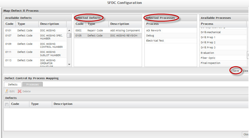
2. Once the list of desired defect codes displays, select the appropriate codes and move them into the Selected Defects panel. Defect codes can be moved by the double-clicking or dragging and dropping method. To remove a defect code from the selected panel, double-click or drag and drop it back in to the available panel.
3. Continue to the Available Processes panel. Filter and move the available processes into the Selected Processes panel.
Figure 11: Map Defects
4. Select Save to map the selected defects to the selected processes. A confirmation will prompt. Select Yes to confirm or No to cancel.
5. Select Clear to remove all defects and processes from the selected panels.
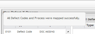
6. Once mappings are saved, a message will display confirming their creation.
Figure 12: Successful Mapping
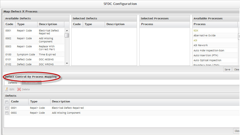
Located at the bottom of the Map Defect X Process page is a panel labelled Defect Control By Process Mapping that displays the mapped defect codes. Once mapping has been completed, the selected defect codes and processes will be available to edit or delete from this panel.
Figure 13: Defect Control By Process Mapping
Located in this panel are two tabs titled Defects and Processes. The Defects tab lists the selected defects for the selected process/processes. The Processes tab lists the selected processes that contain the selected defects.
In either tab, the user can select a Defect code or Process and edit or delete it.
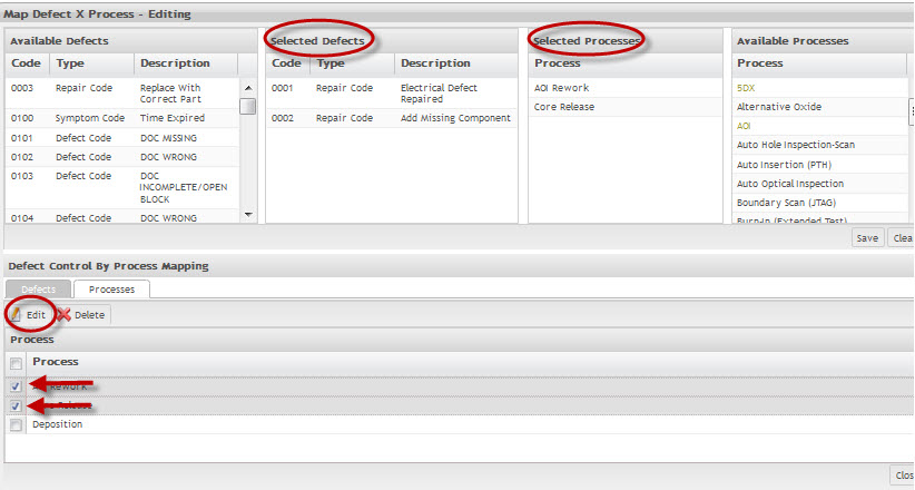
1. To edit created mapping, select a specific defect or process, and then select Edit.
2. The defects and processes attached to the selection will appear in the Selected Defects and Selected Processes panels. The user can move either the defects or processes from these panels by double-clicking or dragging and dropping back into the available panels.
Figure 14: Edit Map
3. To delete a created mapping, select either a defect code or process and then select Delete.
4. A confirmation will prompt. Select Yes to confirm or No to cancel.
Figure 15: Delete Map
Figure 16: Successful Deletion
Note: Once defect codes have been mapped to the appropriate processes, the user must install the updates using the Downloads and Services portlet located under Administration in the SFDC Administrator heading.
Mark as Enabled/Disabled
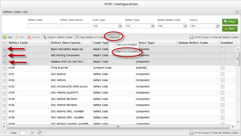
With the functionality, the user can mark single or multiple defect codes as enabled or disabled. If a defect code is enabled, it can be mapped to a process. If a defect code is disabled, it will no longer be available to be mapped to any processes. The user may need to disable a defect code without deleting it if it still exists in certain processes.
1. To disable defect codes, select the appropriate defect codes, and then select More.
2. Select Mark as Disabled.
Figure 17: Disable Defect Codes
The following screen will display:
Figure 18: Disabled Defect Codes
3. To enable defect codes, select the appropriate defect codes (now in red), and then select More.
4. Select Mark as Enabled.
Figure 19: Enable Defect Codes
The following screen will display:
Figure 20: Enabled Defect Codes
Import Defect Codes
This functionality imports Defect Codes into the database from a comma separated value (.csv) file.
1. Create a template file using notepad: sample file name ’template.csv’.
2. Add the following column headers:
Defect Code, Defect Code Description, Code Type
3. Add the desired Defect Code records below the header row separated by comma:
For example:
D000, Defect Code Test, Defect Code
R001, Repair Code Test, Repair Code
K002, Symptom Code Test, Symptom Code
4. Save the file.
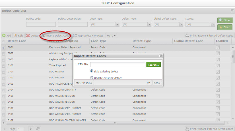
5. To import Defect Codes (.csv file created above), select the Import Defect Code button. This displays the import Defect Codes pop-up.
Figure 21: Import Defect Codes
6. Enter path, or navigate, to desired .csv file to be imported and select Open.
7. Select either Skip existing defect (if applicable) or Update existing defect (if applicable).
Skip existing defect: Skips defect(s) upon import if the Defect Code exists in the database.
Update existing defect: Updates defect(s) upon import if the Defect Code exists in the database.
The selected file will be imported.
Print/ Export Filtered Defect Codes
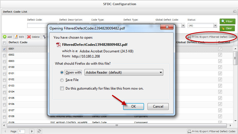
This portlet enables the user to print filtered Defect Codes. The report results include the Defect Code, Description, and Code Type.
1. To print filtered Defect Codes, click the Print/Export Filtered Defect Codes in the Task page. A report is generated and the user is able to save the file or print it.
Figure 22: Print Filtered Defect Codes
Figure 23: Print/Export Report Result
Appendix A
Glossary
Access Control
it is a module that will set the permissions for users and external customers of Sanmina
administrator
the System Administration has full access - all plants, all reports, all users.
component
A component is a specific piece of data that appears on a label, for example: bar code, part numbers, graphic images, line or text. Hence, label components are broken down into several different types: text, graphic images, MDS database values, or a combination of text and database values.
framework
In software development, a framework is a defined support structure in which another software project can be organized and developed. A framework may include support programs, code libraries, a scripting language, or other software to help develop and glue together the different components of a software project.
SFDC Configuration
The rules used to define how SFDC collects data, provides analysis, controls processing and maintains unit histories
Site Minder
Universal login of Sanmina
username
the username is the siteminder username (or a partial string)
Document Revision History
| Date | Author | Title | Version | Change Reference |
| 08/14/13 | Elaine Fonaro | Technical Writer | v 1.0 | This is the first revision of MDS User’s Guide |
| 03/17/14 | Ashley Martin | Technical Writer | v 1.0 | Review and added the new function Map Defect X Process |
| 03/17/14 | Elaine Fonaro | Technical Writer | v 1.0 | Review and format for WIKI |
