Production Control
Contents
- 1 Shop Order Control
- 2 Serialized Item Tracker
- 2.1 SIT – Functionalities Executed from Serialized Items List
- 2.1.1 Accessing SIT (Serialized Item Tracker) Application
- 2.1.2 Serialized Item Tracker List
- 2.1.3 Edit (Update)
- 2.1.4 Return/Obsolete/Damage
- 2.1.5 Resend
- 2.1.6 Additional Information
- 2.1.7 Print/Export or Print/Export Filtered
- 2.1.8 SIT Batch Traveler
- 2.1.9 Receive
- 2.1.10 Receive PTS
- 2.1.11 Resend
- 2.1.12 Print/Export Filtered Ranges
- 2.1.13 Part x Sit Type
- 2.1.14 Location x Sit Type
- 2.2 Appendix A
- 2.3 Appendix B
- 2.1 SIT – Functionalities Executed from Serialized Items List
- 3 Multi-Level Container Pack
- 3.1 Multi-Level Containerization Browser
- 3.2 Container Task Panel
- 3.2.1 Containerize – Opening a Container
- 3.2.2 Containerize – Creating a New Container
- 3.2.3 Create Parent Containers
- 3.2.4 Print Export Filtered Containers
- 3.2.5 Export Filtered Containers
- 3.2.6 Multi-Level Container Pack
- 3.2.7 Accessing the Multi-Level Container Pack
- 3.2.8 Open/Containerize
- 3.2.9 Close/Print Container
- 3.2.10 Create Parent Container
- 3.2.11 Cancel Containers
- 3.2.12 Dimensions
- 4 Kit Verify
- 5 Production Setup
- 6 Incoming
Shop Order Control
- Shop Order Release Module enables user to release Standard and Oracle Shop Orders.
All Shop Orders with status “N” or “R” with increased quantities are displayed.
Shop Orders are displayed in the following colors:
- Black – Shop Order is ready for release
- Red – The number of serial numbers on the Shop Order is incorrect
- Green – All the serial numbers have been generated but the Shop Order status was not changed
-
- Filter enables user to filter Shop Orders by the following fields:
- Shop Order Number – enter desired Shop Order Number for filtering
- Part Number – enter desired Part Number for filtering
- Revision – enter desired Revision for filtering
- Oracle Shop Orders – Shop Orders passed to MDS via MDS/Oracle Interface
Note: Oracle Shop Orders are created as Discrete Jobs in Oracle and are not created in MDS.- Releasable – check to include Oracle Shop Orders that are ready for release
- Not Releasable – check to include Oracle Shop Orders that are not ready for release
- Mapped – check to include Oracle Shop Orders that are already mapped
- Unmapped – check to include Oracle Shop Orders that still require mapping
- Standard Shop Orders
- Releasable – check to include Shop Orders that are ready for release
- Click Filter to filter by above entered criteria, or click Clear to clear filter criteria
- The filtered results are displayed
- Filter enables user to filter Shop Orders by the following fields:
-
- Add Standard Shop Order
- Navigate to Shop Order Release under Shop Order Control module
- Click Add Standard Shop Order icon in Task window
- Shop Order Number – Enter the Standard Shop Order Number
- As a general rule, the Shop Order number should be the same as the Oracle Discrete job number.
- Part Number – Use Find button to select the part number
- Quantity – Enter Shop Order quantity
- If product is panelized and multiple units will be tracked under the same serial number, enter only the quantity of panels
- User Defined – Optional field for user definition of Standard Shop Order
- Revision – Select Revision
- Used only if releasing Shop Order for Revision Controlled parts
- User can enter a revision at the time of release for non-revision controlled part
- Completion Date – Optional field for defining the completion date
- Click Ok to confirm Shop Order addition, or click Cancel to ignore
- The Standard Shop Order has been added
- Release Shop Order per Shop Order Release section 1.8
- Add Standard Shop Order
-
- Oracle Shop Order are the preferred Shop Order methodology. Oracle Interfaced Shop Orders enable WIP tracking and automatic back-flushing in Oracle by mapping Oracle Operation Sequences to SFDC Process/Locations.
- Oracle Discrete Job is created for interfaced part number
- Appropriate Category Set must be defined in Oracle for interface functionality
- Shop Order automatically created via MDS/Oracle Interface
- Shop Order Number, Part Number and Quantity passed via MDS/Oracle Interface
- Serial number completions are reported back to Oracle automatically
- Navigate to Shop Order Release under Shop Order Control module
- Filter or locate the desired Shop Order and click the Map the Shop Order icon
- Oracle Discrete Job is created for interfaced part number
- Oracle Shop Order are the preferred Shop Order methodology. Oracle Interfaced Shop Orders enable WIP tracking and automatic back-flushing in Oracle by mapping Oracle Operation Sequences to SFDC Process/Locations.
-
-
-
- Mapping Oracle Operation Sequence to SFDC Process/Locations will enable SFDC-to-Oracle WIP moves. As units are passed from each process/location, a WIP Move transaction is sent to Oracle for the appropriate quantities. The mapping process is only required once for each part, and any time the Oracle and/or SFDC route is modified.
- The part number must have a Part Route Assignment prior to release, else an error message is displayed.
- As a general rule, map Oracle Operation Sequence to SFDC Process in “Route by Process” configuration – the mapping is then enabled for every location assigned to the same process name.
-
-
-
-
-
- If mapping Oracle Operation Sequence to SFDC Location, keep in mind that WIP moves will not take place when a unit is scanned at a location that is not specifically defined in the mapping.
- Map Oracle Operation Sequence to SFDC Process (or Location)
- Filter and/or Select Oracle Operation Sequence
- Filter and/or Select SFDC Process (or Location)
- Click Add Map icon
- Automatic Map will automatically map Operation Sequence to Process/Location, yet care must be taken to verify accuracy
- Each mapped step added will populate the Mapped Operation Sequences box
- Click the Information icon for details on each mapped step
- Click the Remove icon to remove a specific mapped step
- Perform above steps for remaining Operation Sequence steps desired for WIP movement in Oracle
- Click Save to save mapping, or Cancel to abort
- The Oracle Operation Sequences and SFDC Location/Process have been mapped
- Release Shop Order per Shop Order Release section 1.8
-
-
-
- Close All Shop Orders enables user to Close any/all open Standard Shop Orders. Close Shop Orders functionality is also available through Shop Order Browser module or Shop Order Viewer/Close Shop Order, reference section 4.10
Note: Oracle Shop Orders are not available to close, this task is performed in Oracle- Navigate to Shop Order Release under Shop Order Control module
- Click Close Shop Orders icon in Tasks window – A confirmation window is displayed
- Select the Shop Orders to close
- All Shop Orders available to close are selected by default
- Un-select the any/all Shop Orders that are not to be closed
- Enter Shop Order number in Filter field to filter by Shop Order
- Click Yes to close selected Shop Orders, or click No to abort
- Selected Shop Orders status has been changed to “C” Closed
- Close All Shop Orders enables user to Close any/all open Standard Shop Orders. Close Shop Orders functionality is also available through Shop Order Browser module or Shop Order Viewer/Close Shop Order, reference section 4.10
-
- Print/Export Filtered Shop Orders enables user to print/export the filtered list of Shop Orders. The report results include Shop Order Number, Type, Part Number, Qty, BPP (Boards per Panel), Revision, User Defined, Start Date and Completion Date.
- Navigate to Shop Order Release under Shop Order Control module
- Perform desired Shop Order Filtering per section 1.1
- Click the Print/Export Filtered Shop Orders icon in the Tasks window
- The report results are displayed and the user can save or print it
- Click on Save to save, or Print to print the report results
- Print/Export Filtered Shop Orders enables user to print/export the filtered list of Shop Orders. The report results include Shop Order Number, Type, Part Number, Qty, BPP (Boards per Panel), Revision, User Defined, Start Date and Completion Date.
-
- Serial Number Maintenance – Reference section 3 for further information
-
- Serial Number Assignment – Reference section 2 for further information
-
- Release enables user to release Shop Orders to production
Note: MDS does not allow the release of an “On Hold” status shop order. Reference the Mfg Hold module in the SFDC Configuration Manual for additional information.- Navigate to Shop Order Release under Shop Order Control module
- Perform desired Shop Order Filtering per section 1.1
- Click the Release the Shop Order check-mark icon for appropriate Shop Order to display Release Wizard
- Manually Assign Revision – check to enable user to manually assign revision at release
- Create Skeletons – check if user to create skeletons instead of release serials via algorithm
- Skeletons can be replaced with actual serials utilizing Serial Number Maintenance, reference section 3
- This option is not available when releasing a Non-Serialized batch
- Non-Serialized batch – check if this release is part of a non-serialized batch
- If this is checked, the user is not able to create skeleton serial numbers
- Click Next to continue, or Cancel to abort
- Select a Starting Serial Number
Note: This screen is not displayed if the Create Skeletons check-box was checked in previous step- By Algorithm
- By Product – ONLY if part based algorithm
- Click Next to continue, or Cancel to abort
- Select release type
- Full release – release entire shop order qty
- Partial Release – release defined qty only
- Click Next to continue, or Cancel to abort
- Select or Enter Revision – If “Manually Assign Revision” was checked on first release screen
- If revision controlled part, the user can only select a revision from drop down
- If not a revision controlled part, the user can enter any valid value
- Click Next to continue, or Cancel to abort
- Verify Shop Order release information is correct
- This is the last opportunity to verify Shop Order information prior to release
- Select Print label for the serial numbers generated if labels are printed directly from MDS
- Label Type must be configured in Label Maintenance prior to release
- Select Create text file with serial numbers if an output file of serials is desired
- This file can be used for import into label print software to avoid the risk of releasing incorrect serial format and/or sequence
- Select Create notes to add release notes to Shop Order
- Add notes in regards to the Shop Order release for future reference. For example if partial release was requested for a specific reason.
- All Release Notes are available for viewing and editing in Shop Order Browser, reference section 4.7
- Select Shop Order Linkage if this Shop Order will be linked to another
- Click Next to continue, or Cancel to abort
- If Shop Order Linkage was checked in previous screen, the Shop Order Selection screen is displayed
- Enter the Shop Order and/or Part Number
- If Create text file with the serial numbers was checked in previous screen, the user is prompted to save the output file
- Save all exported serial files in the same folder each time to allow easy and consistent access to output files
- IF Print Label for Serial Number was checked in previous screen, the Print Label for Serial Numbers box is displayed
- Select Label Type
- This is the label configuration from Label Maintenance
- Select Print Queue
- This is the specified output device to which the labels will print
- Init. Printer – Select Yes or No
- Sends command to initialize printer in the event graphics or special formating is requiredPrint
- All available units – prints all serials released
- This is the preferred print method to avoid reprints and/or other serialization errors
- Single Serial – prints a single serial number
- Range – starting and ending
- The range allows the user to print a range of serials released instead of all serials on shop order
- Select Label Type
- Click Print to print serial labels, or Cancel to abort print process
- First and Last serials are displayed – verify for accuracy
- Click Next to continue
- IF Create Release Notes was checked, add desired notes in field provided
- Click Finish to complete release process
- The Shop Order has been released
- Release enables user to release Shop Orders to production
-
- Edit existing Standard Shop Order information. Edit of Shop Order information is usually performed prior to release.
Note: Oracle Shop Orders are not available for editing, any modification is performed in Oracle- Navigate to Shop Order Release under Shop Order Control module
- Perform desired Shop Order Filtering per section 1.1
- Click Edit icon and perform desired modifications
- Part number is not an editable field after initial Shop Order creation
- Click Ok to commit changes, or Cancel to ignore modifications
- The selected Shop Order has been modified
- Edit existing Standard Shop Order information. Edit of Shop Order information is usually performed prior to release.
-
- Delete Shop Orders with an unreleased status
Note: Oracle Shop Orders are not available for deletion, the cancellation task is performed in Oracle- Navigate to Shop Order Release under Shop Order Control module
- Perform desired Shop Order Filtering per section 1.1
- Click Delete icon
- Click Ok to confirm deletion, or Cancel to ignore deletion
- The selected Shop Order has been deleted
- Delete Shop Orders with an unreleased status
- Serial Number Assignment enables user to assign new serials to, and remove serials from, Shop Orders. The Serial Number Assignment functionality is also available through the Shop Order Release module in the Tasks window.
This functionality may be used when serial numbers are provided by a vendor/customer and are not released in sequential order.
-
- Assign Serial Numbers to a Shop Order
- Navigate to Serial Number Assignment under Shop Order Control module
- Perform desired Shop Order filtering by Shop Order Number and/or Part Number and click Filter
- Click the Assign Serial Number icon for the desired Shop Order
- The Shop Order Maintenance/Add Serial Number screen is displayed
- Enter or scan the serial number to add to the Shop Order, and click the blue arrow to add the serial number to Added field
- The following rules apply to the serial numbers being assigned to the Shop Order:
- The part number of the serial number must have an algorithm assigned
- ANY serial number that is not on a Shop Order may be assigned
- If the serial number is Status 30 (Finished), the status will be changed to 15 (Ready to Build)
- The following rules apply to the serial numbers being assigned to the Shop Order:
- Perform above step for all serial numbers to add to the Shop Order
- Click Save to assign the serial numbers to the Shop Order, or Cancel to abort
- The selected serial numbers have been assigned to the Shop Order
- Assign Serial Numbers to a Shop Order
-
- Remove Serial Numbers from a Shop Order
- Navigate to Serial Number Assignment under Shop Order Control module
- Perform desired filtering by Shop Order Number and/or Part Number and click Filter
- Click the Remove Serial Number icon for the desired Shop Order
- The View Serial Numbers screen is displayed
- Double Click the desired serial number to remove from the Shop Order in the Selected Serial Numbers field
- The serial number will move to the Removed items field
- Perform above step for all serial numbers to remove from the Shop Order
- Click Ok to remove the serial numbers from the Shop Order, or Cancel to ignore
- The selected Serial Numbers have been removed from the Shop Order
- Remove Serial Numbers from a Shop Order
-
- Print/Export Filtered Shop Orders enables user to print/export the filtered list of Shop Orders. The report results include Shop Order Number, Part Number, Total Quantity, and Remaining Quantity.
- Perform desired Shop Order filtering by Shop Order Number and/or Part Number and click Filter
- Click the Print/Export Filtered Shop Orders icon in the Tasks window
- The report results are displayed and the user can save or print it
- Click on Save to save, or Print to print the report results.
- Print/Export Filtered Shop Orders enables user to print/export the filtered list of Shop Orders. The report results include Shop Order Number, Part Number, Total Quantity, and Remaining Quantity.
- Serial Number Maintenance enables user to add and/or remove WIP serial numbers on Shop Orders. The Serial Number Maintenance functionality is also available through the Shop Order Release module in the Tasks window.
-
- Filter – Enables user to filter Shop Orders by the following fields
- Shop Order Number – enter desired Shop Order number for filtering
- Part Number – enter desired Part Number for filtering
- Revision – enter desired Revision for filtering
- Operation Type – select desired operation for filtering
- All – select to include Shop Orders in which serial numbers can be added or removed
- Add – select to include only Shop Orders in which serial numbers can be added
- Remove – select to include only Shop Orders in which serial numbers can be removed
- Show On Hold – check to include Shop Orders that are On Hold
- Oracle Shop Orders – check to include Shop Orders passed to MDS via MDS/Oracle Interface
Note: Oracle Shop Orders are created as Discrete Jobs in Oracle, not in MDS. - Standard Shop Orders – check to include Standard Shop Orders
- Show Released – check to include Shop Orders that are status “R” Released
- Show Closed – check to include Shop Orders that are status “C” Closed
- Show Opened – check to include Shop Orders that are Open, but not Released
- Show Canceled – check to include Shop Orders that have been Canceled
- Click Filter to filter by above entered criteria, or click Clear to clear filter criteria
- The filtered results are displayed.
- Filter – Enables user to filter Shop Orders by the following fields
-
- Add Serial Numbers to Shop Orders
- Navigate to Serial Number Maintenance under Shop Order Control module
- Perform desired Shop Order Filtering per section 3.1
- Click the Add Serial Numbers icon for the desired Shop Order
- The Shop Order Maintenance/Add Serial Number screen is displayed
- Click the View All Serial Numbers link to open the Serial Numbers Viewer window
Note: Only WIP serial numbers that are of the same part number and revision are displayed - Click the Print/Export All Serial Numbers icon to print and/or export the serial numbers displayed in the Serial Numbers Viewer window
- The report results are displayed and the user can save or print it
- Click on Save to save, or Print to print the report results.
- Click Ok or Cancel to exit the Serial Numbers Viewer
- Click the View All Serial Numbers link to open the Serial Numbers Viewer window
- Click the Add icon to display the Add Serial Numbers window
- Add Serial Numbers to Shop Orders
-
-
-
- The following rules apply to the serial numbers being added to the Shop Order:
- The serial number must be of the same part number and revision as the Shop Order
- The serial number must be located in a WIP status (>15 but <30) Location
- Only serial numbers that meet the above rules are displayed in the Add Serial Numbers window
- The following rules apply to the serial numbers being added to the Shop Order:
-
-
-
-
- There are three ways to add serial numbers to the Selected Items field:
- Scan or Type the SN to add
- Click the Add multiple SNs icon to display the Add Multiple Serial Numbers Window
- Enter multiple serial numbers, one per line
- Click Ok to confirm, or click Cancel to ignore
- The entered serial numbers were moved from the Results field to the Selected Items field
- Select/highlight the desired serial numbers from the Results field and click the Add selected items icon
Note: Serial numbers can be moved between the Results and Selected Items fields using the arrow icons
- Perform above step for all serial numbers to add to the Shop Order
- Click Ok to confirm, or click Cancel to ignore
- Verify serial numbers to be added before proceeding
- If the user does not wish to add one or more of the units listed, highlight the appropriate serial number and click the Cancel icon just to the right of the list to remove the selected serial numbers before saving
- Click Save to add the selected serial numbers to the Shop Order, or Cancel to abort
- The selected serial numbers were added to the Shop Order
- There are three ways to add serial numbers to the Selected Items field:
-
-
- Remove Serial Numbers from Shop Orders
- Navigate to Serial Number Maintenance under Shop Order Control module
- Perform desired Shop Order Filtering per section 3.1
- Click the Remove Serial Number icon for the desired Shop Order
- The Shop Order Maintenance/Remove Serial Number screen is displayed
- There are three ways to move serial numbers from Removable field to the Removed field
- Double click the desired serial number to move to the Removed field
- Remove Serial Numbers from Shop Orders
-
-
- Note: Serial numbers can be moved between the Removable and Removed fields using the arrow icons
-
-
-
-
- Scan or Type the SN to remove, then Enter to move to the Removed field
-
-
-
-
-
- Click the Remove multiple SNs icon to display the Add Multiple Serial Numbers Window
- Enter multiple serial numbers, one per line
- Click Ok to confirm, or click Cancel to ignore
- The entered serial numbers were moved from the Removable field to the Removed field
- Click the Remove multiple SNs icon to display the Add Multiple Serial Numbers Window
-
-
-
-
- Perform above step for all serial numbers to remove from the Shop Order
- Click Save to remove the serial numbers from the Shop Order, or Cancel to abort
-
- Shop Order Browser enables user to view standard Shop Order information, Release Notes, Linkage, Location and Serial Number information, as well as print labels and Close the Shop Order. The Shop Order Browser is available from the Shop Order Control main page, as well as from the Shop Order Release module in the Tasks window.
Shop Orders are displayed in the following colors:* Black – Shop Order is ready for release
- Red – The number of serial numbers on the Shop Order is incorrect
- Green – All the serial numbers have been generated but the Shop Order status was not changed
-
- Filter enables user to filter Shop Orders by the following fields:
- Shop Order Number – enter desired Shop Order number for filtering
- Part Number – enter desired Part Number for filtering
- Revision – enter desired Revision for filtering
- Operation Type – select desired operation for filtering
- All – select to include Shop Orders in which serial numbers can be added or removed
- Add – select to include only Shop Orders in which serial numbers can be added
- Remove – select to include only Shop Orders in which serial numbers can be removed
- Show On Hold – check to include Shop Orders that are On Hold
- Oracle Shop Orders – check to include Shop Orders passed to MDS via MDS/Oracle Interface
Note: Oracle Shop Orders are created as Discrete Jobs in Oracle, not in MDS. - Standard Shop Orders – check to include Standard Shop Orders
- Show Released – check to include Shop Orders that are status “R” Released
- Show Closed – check to include Shop Orders that are status “C” Closed
- Show Opened – check to include Shop Orders that are Open, but not Released
- Show Canceled – check to include Shop Orders that have been Canceled
- Click Filter to filter by above entered criteria, or click Clear to clear filter criteria
- The filtered results are displayed.
- Filter enables user to filter Shop Orders by the following fields:
-
- Print/Export Filtered Shop Orders – Prints/Exports the filtered list of Shop Orders. The report results include Shop Order Number, Order Type, Part Number, Status, Quantity, Boards per Panel, Revision, Start Date, Released Date and Time.
- Navigate to Shop Order Browser under Shop Order Control module, or the Shop Order Release screen
- Perform desired Shop Order Filtering per section 4.1
- Click the Print/Export Filtered Shop Orders icon in the Tasks window
- The report results are displayed and the user can save or print it
- Click on Save to save, or Print to print the report results
- Print/Export Filtered Shop Orders – Prints/Exports the filtered list of Shop Orders. The report results include Shop Order Number, Order Type, Part Number, Status, Quantity, Boards per Panel, Revision, Start Date, Released Date and Time.
-
- Recall Shop Order enables user to remove non-generic serial numbers from Standard Shop Orders
The Recall Shop Order functionality is not available for Shop Orders with Skeleton serial numbers- Navigate to Shop Order Browser under Shop Order Control module, or the Shop Order Release screen
- Click the Recall Shop Order icon in the Tasks window
- The Recall Shop Order screen is displayed
- Perform desired filtering by Shop Order Number and/or Part Number and click Filter
- Click the Remove Serial Number icon for desired Shop Order number
- The View Serial Numbers window is displayed
- Select the desired serial numbers to remove in the Selected Serial Numbers field
- The selected serial number(s) move to the Removed items field.\
- Click Ok to confirm recall, or click Cancel to ignore
- Recall Shop Order enables user to remove non-generic serial numbers from Standard Shop Orders
-
- Print Traveler enables user to print travelers for status 10 units
- Print Traveler enables user to print travelers for status 10 units
-
- Reprint Traveler enables user to reprint travelers for status 10 units
- Reprint Traveler enables user to reprint travelers for status 10 units
-
- Shop Order Information displays standard information, Release Notes, Linkage, Location and Serial Number Information.
- Navigate to Shop Order Browser under Shop Order Control main page, or Shop Order Release module
- Perform desired Shop Order Filtering per section 4.1
- Click the Shop Order Information icon for the desired Shop Order
- The Shop Order Viewer screen is displayed
- View Standard Information, Release Notes, Location and Serial Number Information
- Click Close to close the Shop Order Viewer screen
- Shop Order Information displays standard information, Release Notes, Linkage, Location and Serial Number Information.
-
- Release Notes – Enables user to add and/or edit release notes for the selected Shop Order
Release Notes should be used any time there is a special case scenario, or explanation required in regards to the Shop Order.- Navigate to Shop Order Browser under Shop Order Control main page, or Shop Order Release module
- Perform desired Shop Order filtering per section 4.1
- Click the Shop Order Information icon for the desired Shop Order
- The Shop Order Viewer screen is displayed
- Enter desired Release Note information
- Click Save to save the new notes, or click Cancel to abort
- Click Close to close the Shop Order Viewer screen
- The Release Notes have been added and/or edited per previous steps
- Release Notes – Enables user to add and/or edit release notes for the selected Shop Order
-
- Edit enables user to edit Standard shop Orders with an Unreleased Status 'N', also reference section 1.9
The Shop Order Edit functionality is not allowed for Oracle Shop Orders.- Navigate to Shop Order Browser under Shop Order Control main page, or Shop Order Release module
- Perform desired Shop Order filtering per section 4.1
- Click the Shop Order Information icon for the desired Shop Order
- The Shop Order Viewer screen is displayed
- Click the Edit icon in the Tasks window to display the Shop Order Edit screen
- Edit the Shop Order Number as desired
- Edit the Quantity as desired
- Edit the User Defined field as desired
- Edit the Revision as desired
- Edit the Completion Date as desired
- Click Ok to confirm modification, or Cancel to ignore
- The Shop Order has been edited per the previous steps
- Edit enables user to edit Standard shop Orders with an Unreleased Status 'N', also reference section 1.9
-
- Delete enables user to delete Standard Shop Orders with an Unreleased Status 'N', also reference section 1.10
The Shop Order Delete functionality is not allowed for Oracle Shop Orders, OR for a Shop Order in which serial numbers have already been started in SFDC.- Navigate to Shop Order Browser under Shop Order Control main page, or Shop Order Release module
- Perform desired Shop Order filtering per section 4.1
- Click the Shop Order Information icon for the desired Shop Order
- The Shop Order Viewer screen is displayed
- Click the Delete icon in the Tasks window to delete the selected Shop Order
- A confirmation message is displayed
- Click Yes to confirm deletion, or click No to abort
- the Shop Order has been deleted
- Delete enables user to delete Standard Shop Orders with an Unreleased Status 'N', also reference section 1.10
-
- Close Shop Order enables user to Close the selected Standard Shop Order, also reference section 1.4
The Close Shop Order functionality is only available for Shop Orders where all serial numbers at a Status 30 or higher.
Note: Oracle Shop Orders are not available to close, this task is performed in Oracle- Navigate to Shop Order Browser under Shop Order Control module
- Perform desired Shop Order filtering per section 4.1
- Click the Shop Order Information icon for the desired Shop Order
- The Shop Order Viewer screen is displayed
- Click the Close icon in the Tasks window – A confirmation window is displayed
- Click Yes to close selected Shop Order, or click No to abort
- Selected Shop Orders status has been changed to “C” Closed
- Close Shop Order enables user to Close the selected Standard Shop Order, also reference section 1.4
-
- Auxiliary Release enables user to release additional quantity and serial numbers to Standard Shop Orders as this option is not available for Oracle Shop Orders. Also reference section 1.8
- Navigate to Shop Order Browser under Shop Order Control module
- Perform desired Shop Order filtering per section 4.1
- Click the Shop Order Information icon for the desired Shop Order
- The Shop Order Viewer screen is displayed
- Click Auxiliary Release icon in the Tasks window
- The Release Shop Order Wizard window is displayed
- Auxiliary Release enables user to release additional quantity and serial numbers to Standard Shop Orders as this option is not available for Oracle Shop Orders. Also reference section 1.8
-
-
-
- Create skeleton serial numbers – check to create skeletons instead of release serial numbers via algorithm
- Skeletons can be replaced with actual serials utilizing Serial Number Maintenance, reference section 3
- Create skeleton serial numbers – check to create skeletons instead of release serial numbers via algorithm
-
-
-
-
- Click Next to continue, or click Cancel to abort
- Enter the desired Quantity to increase
- This value cannot be less than one (1)
- Click Next to continue, or Cancel to abort
- Select a Starting Serial Number
Note: This screen is not displayed if the Create Skeletons check-box was checked in previous step- By Algorithm
- By Product – ONLY if part based algorithm
- Click Next to continue, or Cancel to abort
- Verify Shop Order release information is correct
- This is the last opportunity to verify Shop Order information prior to release
- Select Print label for the serial numbers generated if labels are printed directly from MDS
- Label Type must be configured in Label Maintenance prior to release
- Select Create text file with serial numbers if an output file of serials is desired
- This file can be used for import into label print software to avoid the risk of releasing incorrect serial format and/or sequence
- Select Create notes to add release notes to Shop Order
- Add notes in regards to the Shop Order release for future reference. For example if Auxiliary Release was requested for a specific reason.
- All Release Notes are available for viewing and editing in Shop Order Browser, reference section 4.7
- Select Shop Order Linkage if this Shop Order will be linked to another
- Click Next to continue, or Cancel to abort
- If Shop Order Linkage was checked in previous screen, the Shop Order Selection screen is displayed
- Enter the Shop Order and/or Part Number
- If Create text file with the serial numbers was checked in previous screen, the user is prompted to save the output file
- Save all exported serial files in the same folder each time to allow easy and consistent access to output files
- IF Print Label for Serial Number was checked in previous screen, the Print Label for Serial Numbers box is displayed
- Select Label Type
- This is the label configuration from Label Maintenance
- Select Print Queue
- This is the specified output device to which the labels will print
- Init. Printer – Select Yes or No
- Sends command to initialize printer in the event graphics or special formating is requiredPrint
- All available units – prints all serials released
- This is the preferred print method to avoid reprints and/or other serialization errors
- Single Serial – prints a single serial number
- Range – starting and ending
- The range allows the user to print a range of serials released instead of all serials on shop order
- Select Label Type
- Click Print to print serial labels, or Cancel to abort print process
- First and Last serials are displayed – verify for accuracy
- Click Next to continue
- IF Create Release Notes was checked, add desired notes in field provided
- Click Finish to complete release process
- The Shop Order Viewer screen is displayed, verify the serial numbers added during the Auxiliary Release process are included in the Serial Number Information field, indicating the release is complete
-
-
- Delete Unstarted Units enables user to delete serial numbers of units that have not been started in SFDC
The Delete Unstarted Units functionality will only delete units (serial numbers) that are Status 15, all other serial numbers will remain in SFDC.- Navigate to Shop Order Browser under Shop Order Control module
- Perform desired Shop Order filtering per section 4.1
- Click the Shop Order Information icon for the desired Shop Order
- The Shop Order Viewer screen is displayed
- Click the Delete Unstarted Units icon in the Tasks window – A confirmation window is displayed
- Click Yes to delete unstarted units, or click No to abort
- A confirmation window is displayed prompting user to create a log with the deleted serial numbers
- Click Yes to create a log file with the deleted serial numbers, or else click No if the log file is not desired
- It is good practice to create the log file and save to the location in which the serial number release files are placed for future reference if necessary
- If Yes is selected, the user is prompted for the save location
- Click Save to save log file, or Cancel to abort saving the log file.
- An information message is displayed stating the log file was successfully saved
- Click Ok
- Selected Shop Order status is changed to “N” Unreleased if ALL serial numbers were deleted, else the status remains “R” Released and the Shop Order will display in Shop Order Release screen for Release or Edit.
- Delete Unstarted Units enables user to delete serial numbers of units that have not been started in SFDC
-
- Print/Export Unit Status Details enables user to print/export Shop Order Unit Status Detail Report for the selected Shop Order. The report results include; Serial Number, Location, Unit Status, Quantity, Revision and User Defined.
- Navigate to Shop Order Browser under Shop Order Control module
- Perform desired Shop Order filtering per section 4.1
- Click the Shop Order Information icon for the desired Shop Order
- The Shop Order Viewer screen is displayed
- Click the Print/Export Unit Status Details icon in the Tasks window
- The report results are displayed and the user can save or print it
- Click on Save to save, or Print to print the report results
- Print/Export Unit Status Details enables user to print/export Shop Order Unit Status Detail Report for the selected Shop Order. The report results include; Serial Number, Location, Unit Status, Quantity, Revision and User Defined.
-
- Print Labels enables user to print serial number labels for the selected Shop Order
- Navigate to Shop Order Browser under Shop Order Control module
- Perform desired Shop Order filtering per section 4.1
- Click the Shop Order Information icon for the desired Shop Order
- The Shop Order Viewer screen is displayed
- Click the Print Labels icon in the Tasks window, the Print Label for Serial Numbers window is displayed
- Print Mode:
- MDS – Prints labels developed in MDS
- Label Engine – Prints labels developed in Label Engine
- Select Label Type
- This is the label configuration from Label Maintenance
- Select Print Queue
- This is the specified output device to which the labels will print
- Init. Printer – Select Yes or No
- Sends command to initialize printer in the event graphics or special formating is required
- Print
- All available units – prints all serials released
- This is the preferred print method to avoid reprints and/or other serialization errors
- Single Serial – prints a single serial number
- Range – starting and ending
- The range allows the user to print a range of serials released instead of all serials on shop order
- All available units – prints all serials released
- Click Print to print serial labels, or Cancel to abort print process
- Labels are sent to the selected print queue
- Print Labels enables user to print serial number labels for the selected Shop Order
-
- Shop Order Linkage enables user to link Shop Orders to one another
Need additional explanation here defining purpose and rules.- Navigate to Shop Order Browser under Shop Order Control module
- Perform desired Shop Order filtering per section 4.1
- Click the Shop Order Information icon for the desired Shop Order
- The Shop Order Viewer screen is displayed
- Click the Shop Order Linkage icon in the Tasks window, the Shop Order Selection screen is displayed
- Filter by desired Shop Order and/or Part Number, and select the desired Shop Order to link to
- Click Ok to confirm the Shop Order Linkage
- A confirmation message is displayed, click Yes to confirm, or click No to abort
- The Shop Orders are now linked together
- Shop Order Linkage enables user to link Shop Orders to one another
-
- Display Generic Attributes displays the Generic Attributes List screen
Need additional explanation here defining purpose and rules.- Navigate to Shop Order Browser under Shop Order Control module
- Perform desired Shop Order filtering per section 4.1
- Click the Shop Order Information icon for the desired Shop Order
- The Shop Order Viewer screen is displayed
- Click the Display Generic Attributes icon in the Tasks window, the Generic Attribute List window is displayed
- WHAT ELSE?
- Display Generic Attributes displays the Generic Attributes List screen
-
- Recipe Display functionality is used for viewing and modifying recipe configurations for Shop Orders and Units.
Recipes are unit configuration information including BOM (with substitute parts), reference designators, software load and hardware test information. A default recipe is assigned to shop orders as they arrive in MDS from Oracle.
Recipes can be modified in MDS at the Shop Order and Unit level according to the following conditions:
- Recipe Display functionality is used for viewing and modifying recipe configurations for Shop Orders and Units.
- The entire Shop Order if no units are completed yet
- An individual serial number, or a select number of serial numbers, from a list that are not complete yet (paddle boxes will be used to select the serial numbers).
- All serial numbers on the Shop Order that have not been completed (serial.unit_status-key < 30)
- All serial numbers on the Shop Order that have not been released (serial.unit_status-key = 15)Note: This functionality is only available for Oracle Shop Orders of part numbers that have the appropriate Category Set.
-
-
- Navigate to Shop Order Browser under Shop Order Control module
- Perform desired Shop Order filtering per section 4.1
- Click the Recipe Display icon for the desired Shop Order, the Recipe Display window is displayed
- To Edit a BOM Component, select a node from the tree and edit the form in the right panel.
- Click Ok to confirm the changes, or click Cancel to ignore
- To Add Components to the BOM, click on the Plus icon over the tree
- The
- To Remove Components from the BOM, click on the "minus" button over the tree
- Click Ok to commit changes, or click Cancel to ignore
- Click Close to exit the Recipe Display screen and return to Shop Order Browser
-
Serialized Item Tracker
SIT (the Serialized Item Tracker) is a MDS module designed for effectively importing / creating large numbers of serialized components that will be used later in the manufacturing process. It eliminates much of the overhead of creating serial numbers in MDS one at a time. The serialized components can be created based on a starting serial number and algorithm or from a list of serial numbers scanned or copied from a text file.
The Serialized Items Tracker provides a mechanism to receive/return/obsolete a range of serialized items in MDS. Serialized Item Ranges will be stored in a new SIT_Range table in the mdsc database. Each item in the range is exploded into the Serial table as tracked components. The associating and disassociating these items to units will be done with standard SFDC technology. There are reports and EDI extracts that will be written to support SIT. These reports and extracts are not been defined in this document as they will most likely be written outside of MDS.
SIT also manages and sends e-mail alerts of the serialized items consumption by Low and Very Low Watermarks.
SIT – Functionalities Executed from Serialized Items List
Accessing SIT (Serialized Item Tracker) Application
Click on Serialized Item Tracker in the Shop Floor Control Production Control.
Figure 1: Serialized Item Tracker
To list and search Serialized Items, click on Serialized Item.
The SIT Range List displays:
Figure 2: SIT Range List
The user is able to perform the following actions from the SIT Range List:
Receive; Receive (PTS); Edit; Process; Resend; Additional Info; SIT Batch Traveler; Print/Export and Print/Export Filtered Ranges.
Figure 3: Search Using "Filter" Button
There are three available fields by which to search: Status, Type and Filter By. Enter the information and click on Filter.
Figure 4: Searching by Status
The serialized items created by SIT have a status. The current statuses are Received, Returned, Damaged and Obsolete. See the following description for each one:
- Received: serial number created (SFDC status is the same as the location where the serial was created);
- Returned: this status returns a range of serials, a specific serial or all serials (change SFDC status to "50-Killed");
- Damaged: serial item damaged (change SFDC status to "50-Killed");
- Obsolete: when the serial will not be used anymore but continues to exist. No longer in use or valid (change SFDC status to "50-Killed");
Select a status and click on Find.
Figure 5: Searching by Type
There are four types available: COA label, EUI-48-Intel-MAC, Manually Entered and Non-SN Batch. Selecting a type will display serial number ranges already created for all statuses (receive, obsolete, damage, return).
Select a type and click on Filter.
Figure 6: Searching by "Filter by":
This field is a composed field. To perform a search using the "Filter by" field, select one of the available options (Part Number, Serial Number, PO, PO Line, Packing List or Created User) and fill in the field with the information to search for. Click on the Find button to perform the search.
Serialized Item Tracker List
Clicking on Serialized Item in the main SIT page, the application displays a list with all Serialized Items. Locations are based on the actual SFDC Configuration,
Figure 7: Serialized Item Tracker Range List
Edit (Update)
This Topic discusses how the user can edit (update) the "PO", "PO line" and "Packing List" information.
The Serialized Tracker List page displays to access the "Correct" function.
Select the serial number and click on Edit icon to correct/update the "PO", "PO line" and "Packing List" fields.
The SIT Range Form displays.
Figure 8: SIT Range Form
Enter new values for:
- PO: PO is the Purchase Order of the range being received.
- PO Line: PO Line is the Line Number of the Purchase Order above.
- Packing List: Packing List is the shipping number of the range being received.
In addition, the user is able to update the attribute value. Enter the value in the Value field and confirm.
Click on Update to complete.
Click on Save.
The updates are saved and the list is refreshed.
Return/Obsolete/Damage
For Return, an RMA (Return Material Authorization) number is required for the new range. The application saves this information for historical reporting.
This functionality allows the user to return a range, all available units or a single serial item number to a vendor, according to the chosen option in the Return page. The range is stored in the SIT_Range table as "Returned" for Return, "Obsolete" for Obsolete and "Damaged" for Damage.
Select the serial number and click on Process to choose return, obsolete, or damage to modify an existing serial range, all available units or just a single serial.
Figure 9: Process
The following information can be entered in the page, Range ID, Part Number and Available Units associated to the percent of the available units to be returned.
Return/Obsolete/Damage "All Available Units"
An Operation Summary page is displayed with the result of the operation. All available units must be returned/obsolete/damaged and must be inserted in a new line on "Serialized Items List" with the new status and the serial range information. After any operation, the serial numbers do not have to appear as "available units".
Result: An Operation Summary page is displayed with the result of the operation. All available units are returned/damage or obsolete and a new line on "Serialized Items List" with the new status is inserted. After any operation, the serial numbers do not appear as "available units".
Return/Obsolete/Damage "Single Serial"
An Operation Summary page is displayed with the result of the operation. The single unit must be returned/obsolete/damaged and must be inserted as a new line on "Serialized Items List" with the new status and the serial number information. After any operation, the serial number does not have to appear as "available units".
Result: An Operation Summary page is displayed with the result of the operation. The Single Serial is returned/obsolete/damaged and a new line on "Serialized Items List" with the new status is inserted. After a return operation, the returned serial numbers do not appear as "available units".
Return/Obsolete/Damage "Serial Range"
An Operation Summary page is displayed with the result of the operation. The serial range filled in must be returned/obsolete/damaged and must be inserted as a new line on "Serialized Items List" with the new status and the serial range information. After any operation, the serial range returned does not have to appear as "available units".
Result: An Operation Summary page is displayed with the result of the operation. Serial range units are returned/obsolete/damaged and a new line on "Serialized Items List, with the new status is inserted. After any operation, the serial numbers do not appear as "available units".
Choose one of the available options to return/obsolete or damage (all available units, single serial, or a range (starting and ending serials).
An operation summary is returned. ??????????????????????????????????????????????????????????????
Figure 10: Operation Summary
In this summary you can see all returned/Obsolete/damaged serial number (Passed status) otherwise, the fail reason.
A new line with the new status is created in the serialized list.
Resend
This functionality allows the user to create an attribute for a SIT Range. This triggers another process to send an EDI file to the vendor.
To list Serialized Items, click on Serialized Item Tracker Maintenance in the main MDS page.
Figure 11: Serialized Item Tracker List - Resend
Resend a "Serial Range" from list: the Serial Number Range that was resent is sent to the Vendor through EDI communication.
A confirmation message is displayed.
Click on Yes to complete the resend action or No to cancel.
A confirmation message displays.
The serialized items have been resent.
Additional Information
This Topic discusses the basic information of a selected range as Range ID, Part Number, Quantity and Serial Number List.
Figure 12: Serialized Tracker List - Received
Selecting a serial that has "Received" status, the information of the selected range will be displayed.
Range ID, Part Number, Quantity and Serial Number List.
Click on Print/Export Serial Numbers to display the page that will allow the user to select the status desired. He Print Label option is available.
The report is displayed:
Figure 13: Export Serial Numbers Report Viewer
From this report, the user can save or print the result.
Print/Export or Print/Export Filtered
This Topic will discuss how the print/export function works. This function is used for Print or Export a selected Range or a Single Serial Number.
Figure 14: Serialized Items List – Print/Export
Click on the print/export or Print/Export Filtered button on the Serialized Items Tracker list.
The Report for the selected item is generated and displayed to the user:
SIT Batch Traveler
This Topic will discuss how to verify if the Serial Number bar code range was printed correctly. All the serial numbers that make up the selected range are printed.
Figure 15: Serialized Tracker List - SIT Batch Traveler
Click on the
SIT Batch Traveler icon on the Serialized Items Tracker. The Batch report displays:
Figure 16: Batch Report
Receive
This functionality allows a user to receive (create) a range of serialized items into MDS. The user specifies the beginning and ending serial number, part number and other miscellaneous attribute data. The range is stored in the SIT_Range table as "received" SIT status and has the same status as the Location where it was created (see Location x SIT Type). Individual Items are created in the database as tracked components. A serial number algorithm for the part number needs to be created and released to support generating serial numbers for the defined range.
Note:
SIT works with just with two algorithm types:
1. Shop Order Algorithm (created in the Algorithm Tool);
2. Algorithm manually encoded.
The serial numbers are created and associated to the location (consequently unit status too) that was defined on Location x Sit Type. The following attributes are linked to each serial number:
- SIT Range Pointer (the sit range key)
- SIT Serial Number (itself)
- SIT Date Code
- SIT Lot Code
- SIT Manufacturer Part Number
- SIT PTS ID (only in case of a PTS receive)
The algorithm is updated with the last serial number received.
To start the receive process, click on Receive in the Tasks panel.
To list Serialized Items, click on Serialized Item Tracker Maintenance in the MDS main page.
Figure 17: Receive
Click on Receive button.
Figure 18: SIT Range Form for Non SN Batch, COA Label and EUI-48 types
Type, Part Number, Quantity and Starting Serial (items in blue) are required fields and must be supplied.
Note:
After enter the mandatory fields, the Print Label for receive units pop up is displayed. The user can fill the mandatory fields to print the label or just cancel to proceed with the receive task.
When "Manually Entered" is selected, the "Quantity", "Starting serial" and "Ending serial" fields are disabled. A multi-line text box appears to be filled with the serials. The user is able to paste in a list of serial numbers in this text box, one per line. The quantity field will be automatically updated with the number of serial numbers in the text box.
When the "OK" button is pressed, these serial numbers will be used instead of calculating serial numbers from an algorithm.
Figure 19: Manually Entered Type
Part Number: Select one part number from the drop down list, depending onthe selected type.
Batch Quantity: Calculated if the Starting and Ending serial fields are populated. If the Starting serial and a specific quantity is entered, the system calculates the Ending serial. If the Starting Serial and Ending Serial are populated, the quantity field is disabled.
PO: PO is the Purchase Order of the range being received.
PO Line: PO Line is the Line Number of the Purchase Order above.
Packing List: Packing List is the shipping number of the range being received.
After all fields are populated, a confirmation message is displayed.
Click on Yes to confirm the range creation or No to cancel.
The created range will be displayed in the SIT list.
Non-SN Batch
Always create a batch serial number. The batch serial number quantity is determined by the receive quantity.
If the part number is assigned to an algorithm, the serial number will be validated against it, otherwise no validation will be done.
Receive PTS
This functionality is used by the plants that need traceability. This is controlled using a new set of screens/functions in profile management, so only users with access to this screen will see it or can use it. Conversely, if the existing screen should not be shown in a specific project, it should not be assigned to any profile.
RECEIVE PTS STEPS:
1. Check the correct option in profile maintenance (Receive PTS is the profile’s name option).
2. On SIT Module, there is the task Receive (PTS).
Figure 20: Receive PTS
3. When the user clicks on this task a dialog screen will be shown asking for the PTS ID.
Figure 21: Receive PTS Component
4. Enter a PTS ID.
5. If the PTS ID information is not stored in the MDS tables, then jMDS tries to connect to the PTS database and import PTS information for the PTS ID (like PTS ID’s Part Number, Date Code, Lot Code, MPN). The next time that same PTS ID is entered, jMDS won’t have to connect to the PTS database.
The process to import PTS ID data is as follows:
- jMDS check if the PTS ID is on MDS database.
- If found, the PTS information in MDS database will be displayed.
- If not found, jMDS will try to get connect to the PTS database.
- If PTS records are found, the information will be imported (copied) to MDS database.
- If no PTS records found, a warning message will be displayed stating that the "PTS ID is invalid".
6. After the user clicks the Ok button with a valid PTS ID, the Sit Range screen will open with the imported data filled in.
7. The Range Type is always Manually Entered. Because of this, the combo box is disabled.
8. The Part Number, Date Code, Lot Code and MPN will contain the imported PTS information and is disabled for editing.
9. The Edit operation is available for PTS and allows a user to update the PO, PO Line and Packing List information. If the generic attribute update_pts_data is defined as yes, the Date Code, Lot Code and MPN information will be available for updating as well.
Resend
A Single Serial Number that was resent is sent to the Vendor through EDI communication with the selected option (Build or Remove).
To list Serialized Items, click on Serialized Item Tracker Maintenance in the MDS main page.
Figure 23: Resend Option
Click on Resend button.
A successfully message is displayed.
Print/Export Filtered Ranges
This topic will discuss how the ranges are exported, depending on which type you have selected.
To list Serialized Items, click on Serialized Item Tracker Maintenance in the MDS main page.
Figure 24: Print/Export Filtered Range
Click on Print/Export Filtered Ranges in the Tasks panel.
A report is generated with the SIT range.
From this report, the users can navigate through the pages, print or save the result.
Part x Sit Type
This Topic will discuss how a part number can be associated or disassociated to a SIT type.
Figure 25: Part SIT Type
Click on Part x SIT Type in the Serialized Item Tracker main page.
The SIT Type List page displays.
Figure 26: SIT Type List
To edit a SIT type, select the SIT type and click on the Edit button.
The Part x Type list is displayed:
Figure 27: Add Part x SIT Type
In this page, the user is able to Add (Associate) a Part x SIT Type, edit and disassociate a part from a type.
To add an association, click on Add Part x SIT Type in the Tasks panel.
Figure 28: Add Part x SIT Type
Select a part number to be associated and click on Save.
The selected part number will disappear from this list and will be displayed in the SIT type list, for the previously selected type.
To cancel this action, click on Cancel.
Editing a SIT Type:
The rules for editing SIT Types are the same for COA, MAC or Manually Entered:
Click on the Edit icon to edit a MAC Address or COA Label Type.
Figure 29: Part x Type List – Edit Part SIT Type
The Edit page is displayed:
Figure 30: Part x SIT Type Form
Note: Unless the user checks the check box "Do you want to manage the LVM and VLVM?" this page will not be available for editing.
Low water mark – this is a value set by the user to trigger an alert when the available SN quantity for that part number is low and needs attention. This is defined when the user intends to manage the available quantity of SN. When the LWM is reached, e-mail alerts are sent for the registered addresses.
Very low watermark - this is a value set by the user to trigger an alert when the available SN quantity is very low and has become a critical situation. When the VLWM is reached, e-mail alerts are sent for the registered addresses.
After checking the "Do you want manage the LVM and VLVM?" check box, the data can be edited.
Figure 31: Part x SIT Type Form
On the Part x SIT Type form, click on:
(a) Type a user name, click on add button for the LWM and VLWM CC E-mail:
The e-mail list box is populated with the e-mail from the CC E-mail textbox.
1. Remove button (All Items or Selected Items) for the LWM and VLWM CC E-mail:
The selected e-mail from the e-mail list box is removed from the list.
Notes:
- Selected users will receive e-mails frequently, unless they are removed from the list.
- A CRON job must be configured to send the emails.
Figure 32: Part x Type List - Disassociating Part Numbers
Select a part number to disassociate and click on the delete button.
This selected part number will not be deleted from database; it will just be disassociated from the selected SIT type.
Click on Yes to confirm.
Location x Sit Type
This Topic will discuss how a location can be associated or disassociated to a SIT type.
Click on Location x SIT Type in ne main Serialized Item Tracker page.
Figure 33: Location x SIT Type
The Location x SIT Type List page displays.
It is possible to edit the Location by clicking on the Edit button.
Figure 34: SIT Type List
Edit the location and click on OK button to commit the updates or on Cancel button to cancel them.
Figure 35: SIT Type Form
Note: If the SIT Type already has received a SIT Range, it will not be possible to change it’s Location (see the sample).
Appendix A
Glossary
This glossary is a list of terms with the definitions for them.
Administrator
The System Administration has full access - all plants, all reports, all users.
Component
A component is a specific piece of data that appears on a label, for example: bar code, part numbers, graphic images, line or text. Hence, label components are broken down into several different types: text, graphic images, MDS database values, or a combination of text and database values.
Framework
In software development, a framework is a defined support structure in which another software project can be organized and developed. A framework may include support programs, code libraries, a scripting language, or other software to help develop and glue together the different components of a software project.
LVM
Low water mark – this is a value set by the user to alert when the available SN for that part number are low and it needs attention. It’s defined when the user intends to manage the available quantity of SN. Always when the LWM is reached, e-mail alerts are sent for the registered addresses.
Packing List
Packing List is the shipping number of the range being received
PO
PO is the Purchase Order of the range being received
PO Line
PO Line is the Line Number of the Purchase Order above
SFDC Configuration
The rules used to define how SFDC collects data, provides analysis, controls processing and maintains unit histories
Site Minder
Universal login of Sanmina-SCI
Username
The username is the site minder username (or a partial string)
VLVM
Very low watermark - this is a value set by the user to alert when the available SN are very low and this is a critical situation.
Appendix B
| Name | Type | Required | Min length / Min value | Max length / Max value |
Notes |
| Type | alpha-numeric | x | 1 | 30 | |
| Part Number | alpha-numeric | x | 1 | 25 | |
| Quantity | numeric | 1 | 999999999 | ||
| Starting | alpha-numeric | x | 14 | 14 | mask: AAAAA######### / The last 9 numbers must be minor to the Ending value |
| Ending | alpha-numeric | 14 | 14 | mask: AAAAA######### / The first 5 characters must be equals to the Starting value | |
| PO | alpha-numeric | 1 | 30 | ||
| PO Line | numeric | 1 | 9999999 | ||
| Packing List | alpha-numeric | 1 | 30 |
Multi-Level Container Pack
Multi-Level Containerization Browser
The Multi-Level Containerization Browser displays all multi-level containers created. All container details can be viewed (Container Configurations, container IDs (if it is child show the parent information, in case it has containers inside the screen must displays the tree with all child information).
The containers can be opened for containerization from the list (open a container calls the Multi-level Containerization screen).
The user is able to scan a specific Container ID or a containerized serial number, then the application calls Multi-level Containerization screen. If user scans a non containerized serial number, the application finds the container configuration for the serial part number and displays the available container levels to create a new Container ID.
Accessing the Multi-Level Containerization Browser
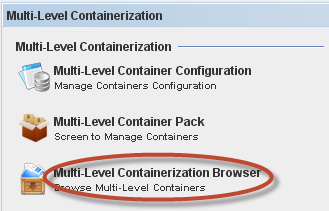
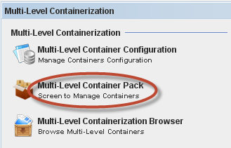
To access the Multi-Level Containerization Browser, go to MDS Client > Multi-Level Containerization > Multi-Level Containerization Browser.
Figure 19: Multi-Level Containerization Browser.
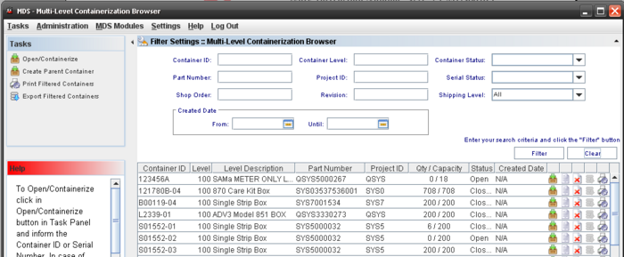
The Multi-Level Containerization Browser window displays:
Figure 20: Multi-Level Containerization Browser
The next topics will describe all available Containerization functionalities.
Containerization Browser List
The Containerization Browser List displays all multi-level containers created and allows performing the following actions:
- Filter Data
- Containerize (add units at containers)
- View a Container
- Delete a Container
- Export Shippable Containers
- Print/Export Containers
Note: It is possible to execute three different actions from the Task Panel:
- Open/Containerize (create or open a container)
- Create Parent Container
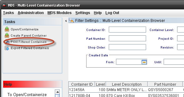
- Print/Export all Filtered Containers
- Export Filtered Container
Filter Settings
Figure 21: Containerization Browser Filter
To create a filter, follow the steps below:
1) Fill in one or more of the following filter options then click on the "Filter" button or press "Enter":
- Container ID
- Part Number
- Shop Order
- Revision
- Container Level
- Project ID
- Container Status: displays the containers opened or closed;
- Created Date: displays all containers created on the chosen date;
- Serial Status and
- Shipping Level.
2) Select the Created Date:
- From/Until: displays the containers created in the data range selected;
Note:
Container Status: displays the containers “Opened”, “Closed”, “Close/Sent”, “Empty”, “Open/Sent” (for any container that was closed and sent/exported to Oracle and “Closed/Sent” for a container that was closed and then sent to Oracle.
Serial Status: displays the containers “Completed”, “Shipped”;
Shipping Level: displays the containers “Yes”, “No”, “All”;
To clear the entered information for a filter, click on "Clear" button.
Add elements inside container
To add elements (element can be serials or containers) inside a container, go to Multi-Level Containerization > Multi-Level Containerization Browser and click on "Open/Containerize" on the Tasks panel or click on Containerize icon in the list.
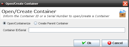
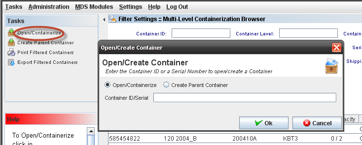
The difference between these actions is that clicking on "Open/Containerize" in the Tasks panel, displays a dialog to the user prompting for the container id or the serial number.
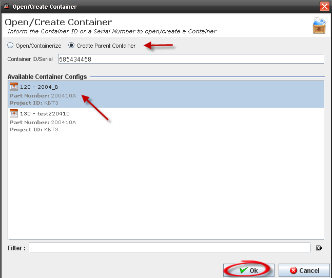
Figure 22: Open/Create Container
Figure 23: Multi-Level Containerization Browser
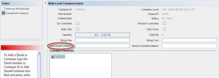
The Multi-Level Containerization window displays:
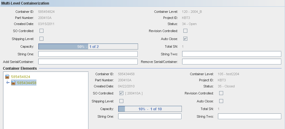
Figure 24: Multi-Level Containerization
The Multi-Level Containerization displays the following information about the parent container selected in the list:
- Container ID; Part Number; Created Date; Container level; Project ID; Status; Capacity, Add Serial/Container and Remove Serial/Container, String 1 and String 2.
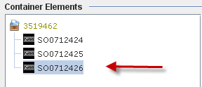
The Container hierarchy is displayed under the "Container Elements" section and the serial numbers in the container are displayed. Clicking on a serial number in the hierarchy, the Location and Containerized Date are displayed.
To add a serial number to a container, type/scan a serial number and press Enter.
The serial number is added under the container in the "Container Elements" section.
NOTE: MULTI-PART Containers allows inserting serials that belongs to different part numbers, but they must comply with the mask.
The "Capacity" is incremented by one unit and the capacity bar reflects the serial added as percentage, if the container capacity is 0, the application assume the max capacity allowed = 999.99 for this container.
Note: To add a container inside another container, the Container to be added must be a lower level. You can add a container that is level 102 to another that is level 104 for example, but you can’t add it to a container that is level 101.
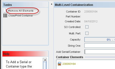
TheRemove All Elements and Close/Print container buttons are displayed in the tasks panel, and if the configuration has Dim per Unit check box checked, a dialog for manage Dimensions is displayed.
Note: The application will not allow users to edit a container that's open for editing by another user. A message is displayed and shows the user name that is using that container.
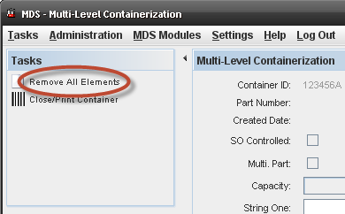
Remove all elements from an opened container
To remove elements from an opened container, go toMulti-Level Containerization Browser and click on the "Containerize" icon for the container created.
Click on "Remove all Elements" task on panel.
Figure 25: Remove All Elements
All the container elements will be removed from the main container hierarchy.
Click on "OK" to save and go back to "Containerize" for that container.
The container is displayed without any elements inside.
Remove elements from an opened container
Follow the steps below to remove elements from containers:
To remove elements from an opened container, go to Multi-Level Containerization Browser and click on the "Containerize" icon.
The Multi-Level Containerization window displays:
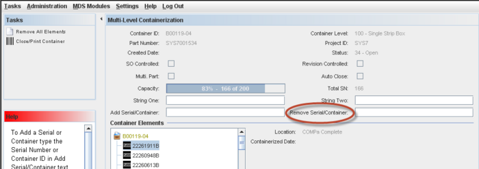
Figure 26: Multi-Level Containerization
To remove a Serial or Container, type/scan the Serial Number or Container ID in the Remove Serial/Container field and press “Enter”. Another method is to select the desired Container or Serial Number in the Container Elements list and double click it.
Save the container by clicking on "OK" and go back to "Containerize" for that container.
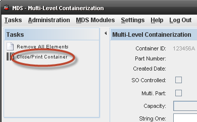
Close/Print container
To print labels, it is necessary define a Label Program (editable combo box) during the container configuration, otherwise, just the Close option is displayed to the user.
Go toMulti-Level Containerization > Multi-Level Containerization Browser > Containerize.
The Multi-Level Containerization window displays:
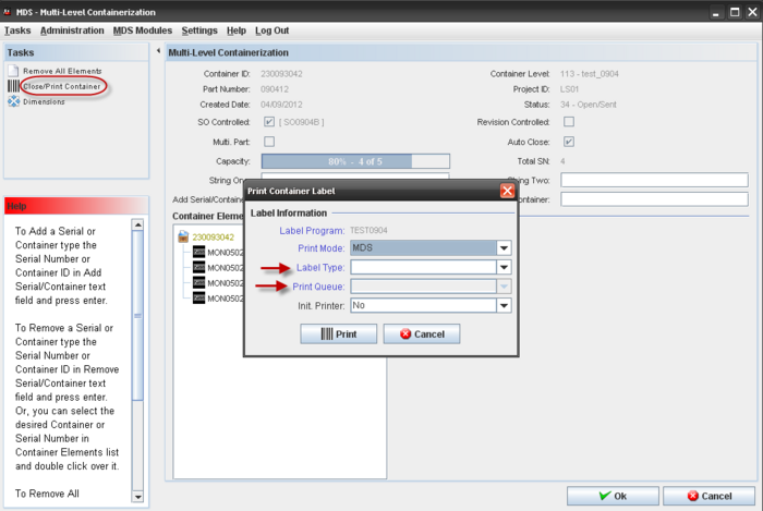
Figure 27: Close/Print Container
Click on "Close/Print Container" button in the Tasks panel.
If the Dim Per Unit Option is set in the container configuration, the user will be able to update the container dimension if necessary.
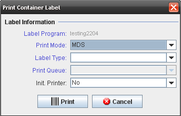
The Print Container Label window is displayed with the following fields:
* Label program (label type + print queue) - ready only. Configured in the Container Configuration; * Label Type – combo box; * Print Queue – configured in the Container Configuration; * Init. Printer – YES/NO
If the label type and print queue configuration is not defined in the container definition, a label type setup in the Label Maintenance module can be used.
Printing a label automatically closes the container. The "Close" icon is disabled for this container in the list.
Automatically close a full container
If the "Auto Close" option is enabled in container configuration, a full container will automatically be closed.
1) Go to Multi-Level Containerization > Multi-Level Containerization Browser and click on "Containerize" icon.
The Multi-Level Containerization window displays.
Type/Scan and add all serial numbers allowed in the container and click on "OK" to confirm.
After performing these steps, the "Add Serial/Container" field is disabled and the container will be closed automatically and displayed in the list with status = closed.
View Container
Follow the steps below to view the container information.
Go toMulti-Level Containerization > Multi-Level Containerization Browser and click on "View Container" icon for a container from the list.
Figure 28: View Container
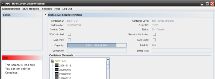
The container view screen is displayed with all the container information, including the serial numbers/containers hierarchy. All information is displayed as ready only.
Figure 29: Container Information
Clicking on a serial number in the hierarchy, the following information of the serial is displayed:
- Location
- Containerized Date
Delete Container
To delete a container, it must be empty (with no serials or containers inside).
Go to Multi-Level Containerization > Multi-Level Containerization Browser, click on "Delete" icon.
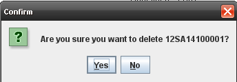
Figure 30: Delete Containers
A Confirmation message is displayed.
Figure 31: Confirmation Message
Click on YES to confirm. The container is deleted from the list.
Export Container from List
Go to Multi-Level Containerization Browser and click on "Export" icon.
NOTE:
It is necessary to configure an FTP server defined for the plant and remember that only the containers flagged as “shipping Level” can be exported.
FTP server must be configured on Generic Attribute sub-module using the following attributes: (ctr_export_ftp_dir, ctr_export_ftp_password, ctr_export_ftp_server, ctr_export_ftp_user).
Attribute recursive_ctr_export = YES configured on Generic Attribute sub-module.
Figure 32: Export Containers
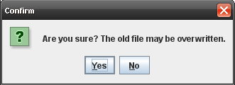
A Confirmation message is displayed:
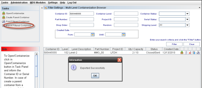
Figure 33: Message Confirmation
Confirm the export clicking "Yes".
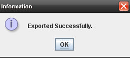
A message saying that the container was exported with success is displayed:
Figure 34: Export Information Message
The ftp "datafile" folder is opened and a .dat file generated for the container exported on the previous step is displayed in that folder. The file name is "ctr" + organization_code + datetime + ".dat".
NOTE: The exported file can be used on the Roboship Oracle (Oracle program that receive the exported files from MDS Client and load it in the Oracle.
Print/Export Container
Follow the steps below to print/export containers:
Figure 35: Print/Export Reports
Click on "Print/Export Container" icon;
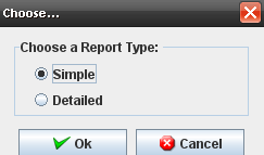
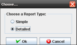
The Choose… dialog displays:
Figure 36: Choose Dialog
Report Type Simple
Select Type = Simple;
The Container willbe printed:
Figure 37: Simple Report
In the Jasper Viewer click on "Save" button, enter the Filename and click to save.
Report Type Detailed
Follow the steps below to print/export containers:
Click on "Print/Export Container" icon
The Choose… dialog displays:
Figure 38: Chose Detailed
Select Type = Detailed
The Container will be printed:
Figure 39: Detailed Report
In the Jasper Viewer click on "Save" button, enter the Filename and click to save.
Container Task Panel
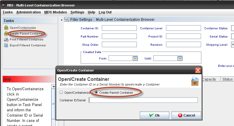
From the Task Panel, the user can open or create a new container, create a parent container and print/export all filtered container configuration.
Containerize – Opening a Container
Containers can be “opened” for serial number adding or removal and “closed” when full or when the operation requires modification of the contained containers.
To open a container, follow the steps below:
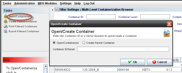
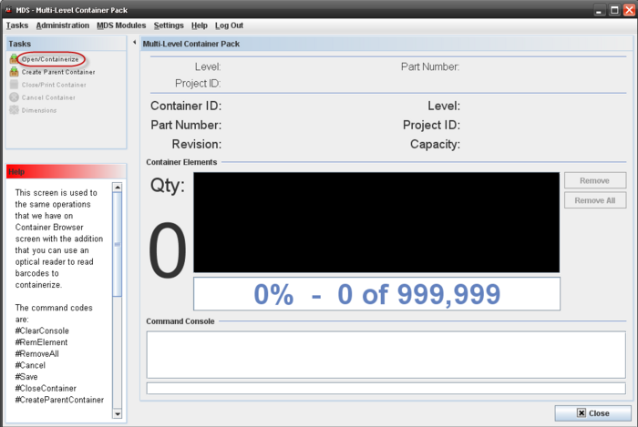
Go to Multi-Level Containerization Browser and click on "Open/Containerize" task on panel;
Figure 40: Open/Containerize
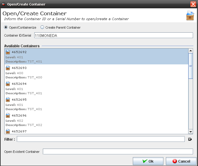
The Open/Create Container window displays. By default, the Open/Containerize option is setting. Type a serial number that is inside the container or a container ID already created.
- A CONTAINER ID is typed:
a) If the container id is not containerized, opens the container id entered (the dialog won't show the non completed possible parents for that container). If the user wants to containerize the container id, a new container should be created or scan parent container ID.
b) If the container id is containerized, displays a warning stating that the container is already inside another container, and then opens the container typed.
- A SERIAL NUMBER is typed:
a) If the serial number is not containerized, a list of configurations will be displayed (the serial number will be automatically added).
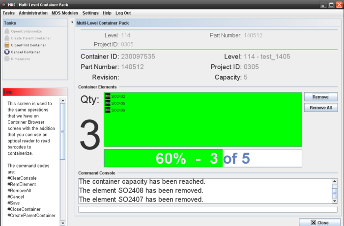
b) If the serial number is containerized, displays a warning stating that the serial is already inside a container, and then opens the parent container
The container that has the serial number entered is opened for containerization and is displayed for editing in the multi-level containerization screen.
Figure 41: Container Edition
The user is able to add or remove serial/container by typing or scanning the serial/container in the Add Serial/Container orRemove Serial/Container field and hitting Enter.
Any attribute related to the container can be added in theString One and/or String Two fields.
Click on Save to save the data.
NOTES:
Figure 42: Remove All Elements
If the user needs to remove all elements from container, go to the Tasks panel and click on Remove All Elements.
Figure 43: Remove All Elements
To close a container, it can not be empty. Click on Close/Print Container in the Tasks panel. A confirmation message is displayed before close/print the container.
These notes are the same for creating new containers.
Containerize – Creating a New Container
Go to Multi-Level Containerization Browser, click on "Open/Containerize" task on panel;
The Open/Create Container window displays:
Figure 44: Open or Create a Container
The Open/Create Container screen displays:
Figure 45: Open/Create Container
For this example, note that the container configuration created before is displayed in the Available Containers list.
Double click on a container configuration or click on OK to associate it to a new container;
The multi-level containerization screen is displayed with the serial number added to the elements hierarchy. A new container ID is created.
Now, the user can add elements to the container until the capacity is reached.
Figure 46: Container Elements
Click on Ok to save the new container. A Confirmation message displays. Click on OK to confirm.
Create Parent Containers
Go to Multi-Level Containerization Browser, click on "Create Parent Containerize" task on panel;
The Open/Create Container popup displays:
Figure 47: Create Parent Container
Note that the default is Create Parent Container selected.
- A SERIAL NUMBER is typed:
a) If the entered serial number is not containerized, a list of configurations is displayed (the serial number is automatically added).
b) If the entered serial number is containerized, displays a warning stating that the serial is already inside a container, and then opens the parent container.
- A CONTAINER ID is typed:
a) If the entered container id is not containerized, a list of configurations is displayed (the container is automatically added).
b) If the entered container id is containerized, displays a warning stating that the serial is already inside a container, and then opens the parent container.
After entering the container id/serial, the Open/Create Container dialog is displayed. Select an available container configuration and click on OK.
Figure 48: Open/Create Container
The Parent Container is created and other containers can be added. Only closed containers can be added to a parent container and the level must be lower than the parent container.
Note: If the container is not full, a message is displayed to alert the user. Click on YES to continue. If theLog option was set in the container configuration, the user needs to enter a log to continue.
The Multi-Level Containerization screen is displayed and the user can see the container data and only a few fields can be edited:
Figure 49: Multi-Level Containerization
The user is able to add or remove serial/container by typing or scanning the serial/container in the Add Serial/Container orRemove Serial/Container field and hitting Enter.
Any attribute data related to the container can be entered in theString One and/or String Two fields.
Click on Save to save the data.
Every time that a container is closed, the print label dialog displays unless the option “Disable printing when…” in the Container Configuration was selected.
Figure 50: Print container Label
The user needs to select the Print Mode, the Label Type (it must be assigned to the containers’ part number) and the Print Queue and click on Print. If the user clicks on Cancel, to print a label for this container, it must be opened and closed again.
Print Export Filtered Containers
1) To print or Export filtered containers, go toMulti-Level Containerization Browser, click on "Print/Export Filtered Container" task on panel;
Figure 51: Print/Export Filtered Containers
The report is generated according the filter:
Figure 52: Print/Export Filtered Containers Report
Click on "Save" button to save the result;
A CSV file with the Containers report is saved in the selected path.
Export Filtered Containers
1) To Export filtered containers, go toMulti-Level Containerization Browser, click on Export Filtered Container" in the task on panel;
Figure 53: Print/Export Filtered Containers
Multi-Level Container Pack
The Multi-Level Container Pack was developed to help users that work with data collector and use the bar code commands.
If a user A is working on any container and a B user tries to update the same one, it is displayed a warning message to alert that this container is locked for editing by "A" user.
The container will be available for a new editing when user A complete the updates and close it.
Accessing the Multi-Level Container Pack
To access the Multi-Level Container Pack, go to MDS Client > Multi-Level Containerization > Multi-Level Container Pack.
Figure 54: Multi-Level Container Pack
The main Multi-Level Container Pack window displays:
Figure 55: Multi-Level Container Pack main window
This screen is used to execute the same operations of Container Browser screen with the addition that the users can use an optical reader (data collector) to read barcodes to containerize. The Container Pack screen allows to manage (Create, Open, Add Elements, Remove Elements, Close) parent containers by commands that can be typed or scanned from bar-codes. The screen displays container details with big font size and colors.
The following commands can be executes from the Command Console:
- #ClearConsole: this command will clear all data entered in the command console;
- #RemElement: type this command to remove elements from container;
- #RemoveAll: it will remove All elements from container;
- #Cancel: this command will cancel all information entered;
- #Save: it will save all data from container;
- #CloseContainer: close the container;
- #CreateParentContainer: create a parent container for the actual container;
In addition, to represent some information are used colors and sounds:
- Black: Closed.
- Green: Opened with 80% of capacity free.
- Yellow: Opened with 80% of capacity full.
- Orange: Opened with 100% of capacity full.
- Red: Error message.
Sounds:
- 1 beep: Error message.
- 2 beep: with 80% of capacity full.
- 3 beep: with 100% of capacity full.
Open/Containerize
To Open/Containerize, click on Open/Containerize in the Tasks Panel.
NOTE: The first time that the users open or create a container, must be by clicking on the link.
Figure 56: Open/ Containerize
Figure 57: Add Elements
Now the user can include elements till reach the capacity.
Close/Print Container
This function is exactly like Close/Print Container in the Container Browser module. For more information, go to [#_d)_Close/Print_container Close/Print Container].
Create Parent Container
This function is exactly like Create Parent Container in the Container Browser module. For more information, go to [#_2.2.2c_Create_Parent Create Parent Container].
Cancel Containers
This functionality just cancels all data entered for the active session, from the last opened container.
Dimensions
The Dimensions must be filled using the same rules for Multi Container Browser.:
- The user can define the Container dimension filling the weight (kg), height (m), length (m), volume (m3) and width (m). Selecting the Dimension per Unit flag, it is possible to fill for each configuration container. If the dimension is in different measure, the data will be converted.
Note:
The dimensions icon will be enabled if the Dim. Per Unit flag is set.
Kit Verify
Alert Template
To access the Alert Template functionality, from Tasks panel, click on Alert Template.
Figure 60: Alert Template List
Figure 61: Alert Template List
The Alert Template is created in the “Alert Template” screen where the user can save and keep it.
It is possible to search, add, edit, delete or copy alerts templates.
Adding Alert Template
Figure 62: Adding Alert Template
The Add Alert Template window displays:
Figure 63: Add Alert Template
- In the Template name field the user should write the Template Name (This field is the email subject).
- In the Content field the user should be write the message for the alert with the Tokens that he wants to use. It is possible to add text and also select or type the available tokens.
Note: The Available Tokens box allows to the user to select the Tokens and when the user clicks in the tokens these tokens are going to the body box.
To add an Alert Template, follow the steps bellow:
- In Task Panel click on "Add Alert Distribution" option;
- Fill the mandatory fields (Template Name and Content);
- Click on "Ok" button;
- Confirm the Alert Template creation.
Editing Alert Template
Figure 64: Editing Alert Template
Follow the steps bellow to edit an alert template:
- On the Alert Template list, select an existing Alert;
- Click the Edit icon;
- The Alert Template screen displays. It is the same for Add alert template.
- Change the mandatory fields;
- Click "OK" button
- Confirm the Edit.
Copying Alert Template
Figure 65: Copying Alert Template
The copy feature allows the user to copy alert information. Follow the steps bellow:
- On the Alert Template List, select an existing Alert;
- Click the Copy Icon;
- Change the mandatory fields;
- Click "OK" button.
Deleting Alert Template
Figure 66: Deleting Alert Template
Follow the steps bellow to delete an Alert:
- On the Alert Template List, select an existing Alert;
- Click the Delete icon;
- Click "OK" button.
- A confirmation box displays.
- The Alert is deleted.
Production Setup
Introduction
This page explores every detail of production setup, from setup procedures for different scenarios, production line handling, workstation handling, to picklist defining.
Production Setup Procedure
For different scenario, the production setup procedure may be different. Below are two common scenarios user may usually encounter:
Scenario 1.
Production Setup for a new (or previous built) product item on a new shop floor production line, suggested following the steps below in PTS:
|
1. Convert and upload SMT Picklist into PTS. |
Refer to SOP-5-I-PTS0014-C |
| 2. Create a New Production Line. | Refer to Create a New Production Line. |
| 3. Create all required Workstation(S). | Refer to Create a New Workstation. |
| 4. Add the Workstations into the Production Line by sequence. | Refer to Add a Workstation into a Production Line. |
| 5.Define Workstation Process Sequence in a Production Line. | Refer to Move Up Process Sequence. |
| 6.Define Workstation Parameters for each added Workstation(s). | Refer to Workstation Setup. |
| 7.Define Picklist for each above added Workstation(s). | Refer to Define Picklist. |
| 8.Location Mapping for PTS workstation. (Optional) | Refer to Location Mapping |
| 9.Set Production Online. | Refer to Set Production On/Off-Line. |
Scenario 2.
Production Setup for a previous built production item on where previous built shop floor production line, suggested to follow the steps below in PTS:
| 1.Convert and upload SMT Picklist into PTS. | Refer to SOP-5-I-PTS0014-C. |
| 2.Define Picklist for each Workstation which corresponding to the associated Production Line. | Refer to Define Picklist. |
| 3.Set Production Online. | Refer to Set Production On/Off-Line. |
Note 1: The following content is a general training guide that is not to provide a standard shop floor production process flow for all individual plant or department.
Note 2: Please avoid setup a new assembly on any existing created production line in PTS. It is recommended to have a PTS production line naming setup for one specific assembly exclusively.
Production Line
This section will introduce how to create new line by PTS system.
Click Production Status > Production Setup
Create a New Production Line
Please refer the following example to create new production line!
Select and click Create a New Production Line as above figure marked.
- Enter the new Production Line Name. (See following for naming format suggestion).
- Click Create button to create new production line.
| Suggested naming format for Production Line | |
| By Shop Floor Location | |
| Format: | Area Location + Production Zone - Production Part Number - Production Process - Production Side |
| Area Location | F (Floor), G (Ground) |
| Production Zone | Floor level or zone area in production either in alpha or number format. |
| Production Part Number | as named |
| Production Process | S (SMT), H (Hand Load) |
| Production Side | T (Top), B (Bottom) |
| Example | F2-ABC12345-S-T Production Line for product ABC12345 top side SMT production at 2nd floor |
| By Production Process | |
| Format | Production Process + Production Zone – Production Part Number – Production Side |
| Production Process | S (SMT), H (Hand Load) |
| Production Zone | Floor level or zone area in production either in alpha or number format |
| Production Part Number | as named |
| Production Side | T (Top), B (Bottom) |
| Example | S2-ABC12345-T Production Line for product ABC12345 top side at SMT Line/Zone 2 |
Search a Production Line
Search the existing production line as follows example:
- Enter the production line name or key words in the Search Line Name field.
- Click Go
- The related production line will be listed in Production Line Available text box.
Rename a Production Line
According to requirement to rename production line name.
- Select the production line from the “Production Line Available” Menu.
- Click Rename Production Line
- Enter the New Name in “New Production Line”.
- Click the Change button to rename the production line.
Note: Production line name can be changed only when the production line is in off-line mode. (See Set Production Off-Line)
Set Production On/Off line
This module allows user to
Set Production On-Line
Once you have production line and workstation ready, now we need to set production line to be On-Line mode for starting work order production. You can’t load material or scan board if the production line is off.
- Select the production line to be set on line from the Production Line Available Menu.
- Choose Set Production On/Off Line functional module.
- Enter a released Work Order number if known or Select the work order from the list by clicking Show button.
To be continued on the following page for showing the screen if you click Show
- Select the Work Order (you can view the BOM detail by clicking the BOM P/N).
- Click Check in the BOM/PL column to verify the BOM against the defined picklist and vice versa under two sessions if there is unmatched items:
To be continued on the following page for showing the error screen once you click Check and if there is any unmatched item
- Items not exist in BOM
To compare and validate all material placements in SMT placement program (i.e. PickList) not exist in Oracle BOM.
- Items not exist in PickList
To compare and validate all material placements in Oracle BOM not exist in SMT placement program (i.e. PickList).
- Fill the required Work Order with associated production ECN.
- Click On-Line button to set the production line online after confirmed the Work Order and ECN selection.
Note: If you have the situation that your selected work order BOM components unmatched the defined Picklist, you need to follow below confirmation and update accordingly:
- Confirm on the Work Order you enter/select is associated with the latest ECN or not.
- Confirm the Picklist you defined is correct or not.
Set Production Off-Line
Once the work order is completed on the production line, the production line needs to be set to Off-Line mode.
- Select the production line to be set on line from the Production Line Available Menu.
- Click Set Production On/Off Line functional module.
- Click the Off-Line button.
Hide Production Line
This function can be used when one line is in offline status.
- Select and click one off line.
- Click OK button to hide this production line.
Recover Production Line
This module is used to recover the line that was hidden in Production Setup module.
- Select and click Production Status >Recover Production Line from PTS main menu.
- Select one line user wants to recover from Production Line Name drop down list.
- Click Send button.
Workstation
Create a New Workstation
It is used by engineer to create new work station in PTS
Click Production Status > Production Setup from PTS main menu.
- Click Create a New Workstation from the functional option menu. (See following section for naming format suggestion).
- Workstation: Enter the workstation name
- Workstation Type: select one workstation type.
- Click Create button to create the new workstation.
Note:{color:#3366BB;} The workstation type should be added first in SMT Machine > Workstation Type module.
| Suggested naming format for Workstation | |
| By Shop Floor Location | |
| Format | Area Location + Production Zone - Placement Machine |
| Example | F2-CP6B |
| Explanation | Fuji CP6B placement machine located at 2nd Floor |
| By Production Process | |
| Format | Production Process + Line/Zone - Placement Machine |
| Example | S2-CP6A |
| Explanation | Fuji CP6A placement machine located at SMT Line 2 |
| By Placement machine model with associated serial number | |
| Format | Placement machine model – Placement machine serial number |
| Example | CP6-SN12345 |
| Explanation | Fuji CP6 placement machine with its own unique machine serial number SN12345 |
Add or Remove Workstation
This module is used by engineer to add or remove workstation(s) for selected production line.
Click Production Status > Production Setup from PTS main menu.
Adding Workstation into a Production Line
Add workstation(s) to selected production line when production line is in offline status.
- Select the production line from the Production Line Available menu.
- Click Add or Remove Workstation from the functional option menu.
- Select the workstation name from Workstation pull down list to add to the specific production line.
- Click Add button to add the workstation.
Note: After created a new workstation, user needs to add new workstation to production line via this function.
Remove a Workstation from a Production Line
Remove workstation(s) from selected production line when production line is in offline status.
- Select the production line from the Production Line Available menu.
- Click Add or Remove Workstation from the functional option menu.
- Select the workstation name from Workstation pull down list which is under In Use to delete workstation from the specific production line. (Such as above figure marked)
- Click Delete button to add the workstation.
Rename or Delete Work Station
This function is used to change workstation name or delete workstation for offline production line.
Click Production Status > Production Setup from PTS main menu.
- Select the production line from the Production Line Available menu.
- Click Workstation Maintenance from the functional option menu.
- New Workstation: input new workstation name to replace original name.
- Workstation Type: re-select one type from dropdown list if needed.
- Click Change button to change workstation name and save modified result.
- Click Delete button to delete this workstation.
- Workstation type must be added first in ‘SMT Machine > Workstation Type’ module.
- If one workstation is assigned to 3 production lines, renamed workstations will affect at these 3 lines.
- CAUTION: Please be noted that it is compulsory to remove workstation from all involved production line(s) before deleted the workstation. (See Remove a Workstation from a Production Line ) An error message “Workstation is now used by another production line!” resulted if the workstation is still under any existing offline/online production line.
- If one workstation was deleted, user can’t reuse the same name again.
Move Up Process Sequence
Used by engineer to redefine the proper workstation sequence for the production line if the previous setup is incorrect. The selected workstation would move one step onward in the procession list. But the first workstation in the production line will not move.
Workstation Setup
This module is to setup the scanning behavior and scanning rules for each defined Workstation under associated Production Line.
Figure: Workstation Setup Parameters
Select the production line from the Production Line Available menu and select the workstation to be set up in the Work station Available Menu. Click Workstation Setup option as hightlighted above, a workstation setup page shows up on the right of the window:
- Barcode Regulation(Recommended):
Fill in “Barcode Regulation” based on the serial number mask which applied on each PCB serial number barcode label. If blank, no serial number will be validated for all PCB serial scanning.(click ![]() button to see the detailed regulation)
button to see the detailed regulation)
- Scanning Behavior(Mandatory):
- Scan By Later Workstation: All this workstation material placements can be recorded with the next Workstation(s).
- Must Scan At this Workstation: All this workstation material placements are required to be recorded at this Workstation before reach and/or scan at next Workstation(s).
- Scan for Previous Workstation: All this workstation material placements will be recorded with the previous Workstation placements.
- Scan Board/Panel(Mandatory): Select the Scan Board/Panel for both 1st Side and 2nd
- Board: Each individual PCB board number.
- Panel: Each PCB panel number.
- Serial: Each PCB serial number.
- Scan Extra S/N(Mandatory): Define if required extra serial need to be scanned. If it is required to scan the PCB boards additional barcodes such as, the package label, select “Yes.” Default is “No”.
- S/N Regulation( Mandatory if Scan Extra S/N above is Yes): Define the serial number barcode regulation.
- Completed MSD( Mandatory if MSD control is needed): Default is “No”.
Note: MSD control is only applied to the workstation(s) prior reflowing process.
- Scan Side( Mandatory if Completed MSD above is Yes): Define which production side(s) needed to be scanned.
- 1st Side: First PCB production side or One PCB production side.
i.e. Such as PCB’s TOP side production only which do only have material placements on one PCB side. - 2nd Side: Second PCB production side.
i.e. Such as TOP side can be called 2nd Side as it is the second production side after BOTTOM side placement finished. - 1st & 2nd Side: Top and Bottom
i.e. Both production sides required to be scanned at the same Workstation.
- Scan Material(Mandatory) :
- Select “Material Barcode” (For plant which used PTS format material label that included an unique printed PTS material barcode).
- Select “Manufacturer P/N” (For plant which might used standard plant approved / developed material label that included printed SSCI Part Number barcode).
- Select “SSCI P/N.” (For plant which might used manufacturer provided label that included printed manufacturer Part Number barcode)
- Material Run Out Stop (Recommended): Define if the system automatically stops machine when material runs out. Select Yes or No. Default option is No.
Note: If Material Run Out = Yes under System Setting page, system automatically stops the machine when material runs out regardless of which option is selected here; If Material Run Out = No, Yes should be selected here if user wants to set system to automatically stop machine.
- Dual Sled (Optional): Define if the station supports dual tables. Select Yes or No. Default option is No.
Note: If Yes is selected, there will be two tables showing up on the bottom of the Load Material and Prepare Material page, and there will be a Dual Sled option displayed on Scan Board Barcode allowing user to select Table 1 or Table 2.
- Request Material (Recommended): Define if the system automatically requests material from warehouse when material reaches a pre-configured quantity. Select Yes or No. Default option is No.
- Process(Mandatory):
- SMT: For SMT Machine workstation
- Hand Load: For Manual process workstation
- AI: For Auto Insertion workstation
Note: Different setup option defines different material loading process. Refer to the Load Material work instruction for more detail.
- Check P/N In Picklist(Mandatory): Define whether or not to check part numbers in BOM with the ones in Picklist when production line is on-line. Select Yes. Default option is No.
- Allow To Change BOM P/N(Mandatory): Define whether or not to check BOM part number consistency of current scanning and previous scanning when the same board is scanned more than once. Select Yes. Default option is No.
- Click on
 button to set up the workstation or save changes to the workstation.
 - Click on
 button to view the change history of a selected workstation.
 - Click on
 button to go back to previous window without saving changes.
Define Pick List
This module is for assigning the early prepared/loaded SMT placement program into a Workstation under the specific Production Line.
- Select the production line from the Production Line Available Menu.
- Select the workstation from the Workstation Available Menu.
- Select the Define Picklist.
- Enter the Picklist name into Search textbox.
- Click “Go” to search Picklist name.
- Select the Picklist name to view material placements with reference designator listing(refer to below figure).
- Verify Picklist and submit
a. Verify and confirm the placements and corresponding reference designator, click Send to assign the selected picklist into the Workstation.
b. Click Cancel to return to the Select Picklist menu.
Note: For additional detailed Picklist information, refer to EZPickList Work Instruction SOP-5-I-PTS0014-C.
Location Mapping (optional)
This sub-module is designed to map PTS workstation with SFDC location, so that SFDC will forward serial number information to pre-mapped PTS workstation upon board scanning, which help to avoid duplicate board scanning and improve production efficiency.
To map a PTS workstation with a SFDC location, please select the workstation of a production line, and click on Location Mapping, refer to below figure:
- Update an existing mapping, click on corresponding “Edit” button;
- To configure a new mapping, click on the “Create” button and a window will pop up as below:
- MDS User ID(Mandatory): SFDC user ID at MDS. Select from the drop-down list.
- Location Name(Mandatory): Fill in SFDC location name that to be mapped with selected PTS workstation.
- Device ID(Optional): Fill in SFDC Device ID.
- Click on Send button to complete the mapping and Cancel takes you back to previous interface.
Incoming
Material Labeling
This section is used by IQC department to print label for direct material. All material barcodes created will follow the PTS serial
number given as a default. Material barcode can also be manually input for specific need.
Prerequisite
- Understanding of Oracle receiving process
- Proper PTS access
- already existed RT (Receipt Traveler) number
- The warehouse staff must ensure that all the received materials must have their correct RT numbers
Operations
Click Incoming > Material Labeling from main PTS pull down menu.
- Receipting Number: Enter valid Receipting Number for Material Labeling page as above figure shown. (Compulsory)
- SSCI Part Number, Manufacturer Name/Vendor Code, Manufacturer P/N, Supplier Name,Receipting Quantity and Printing date
will be shown automatically after inputting Receipting Number. (user must select one SSCI P/N if one RT has multi SSCI P/N)
- Copy: default is 1, user can key in qty to confirm how many label copies need to print for current label.
- Material Barcode: input barcode or default it Auto. Generally, we recommend using default Auto.
- Quantity: default is 0, user must key in single pack qty. Note:The
message "Quantity*Copies > Remained Quantity!" will be shown and not allow user to print label when “Material Label
Quantity Control" was set Yes at System Setting page, the entered Quantity
multiplied by Copies can not be greater than Remained Quantity.
- Lot Code: lot code will be provided by vendor and can be found each material vendor’s sticker.
- Date Code: Date code will be provided by vendor and can be found each material vendor’s sticker.
- MFG Date: show MFG date on label, but system will not save this data into database.Note:It’s optional, this option only work on when ‘MFG Date=Yes’ at [[PTS System
Definitions#Material_And_Labeling|System Setting]] page.
- Pb-Free Category: default is ‘leaded’; user can select it from dropdown list to define material Pb Category: Leaded, Pb-free,
e1-e7 (regard as lead free), R5 and C5 in list.
It needs to define when
label creation. Once created; it can’t be changed.
- High Value: it will show the material whether is high value material. This option only be shown when “High Value Mark” is
YES at System Setting page.
- MSD Level: default is undefined; user also can select it from dropdown list to define material MSD level.1, 2, 2a, 3, 4, 5, 5a, 6
in list.
MSD material will be regarded as high value material if MSD
Level is greater than “High Value Level” parameter user defines at System Setting
page.
It needs to define when label creation. Once created; it can’t be
changed.
* System will show $ logo on the label for high value material (i.e. “High Vale” shows YES or MSD Level over “High Value
Level” setting.)
- Accept Property: default is Accepted. User can change status for this material by selecting the option. This information will
only print at label. It will not save to database.
- If select Accepted – accept this material and can be used in production.
- If select Rejected – reject this material, this indicates that material should not be used (material will only be blocked at loading time if patch 3.4.1-1 has been applied this will also have a saved record defined in database for hold that was applied to prevent loading, otherwise feature is limited to printing word "rejected" on material label,and material can still be used in production and will not be saved in database therefore no validation or systematic blocking is applied )
the label and not saved to the database there is no validation or systematic way to prevent only a visual indicator.
- Due Date(changed to Next Inspection Date since PTS v3.4.3): QC next inspection date. This due date is for QC inspection
but not material due date. Default is current date instead of next check date.
- IQC Result/Remark: this is for remark use; user can input or leave it blank.
Warning Message
Click Send to save entered data. The warning message will be shown when Lot Code or Quantity is empty.
[[Image:Material
Labeling QTY Warning Message.JPG|thumb|none|Material Labeling QTY Warning Message.JPG]]
Label printer
If the barcode generated successfully, the Print icon will be displayed.
- Click Print icon to print it.
- Ensure each label passes visual check and is checked by the scanner
- Make sure every item on label matches the material
- Paste label on the same surface where supplier label is located (Do not cover the feeder hole or other labels on the packing)
Reprint Material Label
This module is used by IQC to reprint material barcode for reprint the existing PTS printed label due to the quantity is been
updated or poor quality label is been printed or damaged.
Prerequisites
- Material receiving process knowledge.
- Material label is been PTS printed.
Operations
Click Incoming > Reprint Material Label from PTS main menu.
- Enter the “Material Barcode” (all related information will show up automatically).
- Confirm and enter the “Current Quantity.”Note:The message“Current
Quantity > Total Quantity!” will be shown and not allow user to print label when “Material Label Quantity Control" was set
Yes at System Setting page. The entered Current Quantity can not be
greater than Total Quantity.
- Define Pb-Free Category, Accept Property, and Next Inspection Date as it appears on the MFR label.
- Input the reference information in the “Append Remark” field if any.
- Click “Reprint” to print out new label.
All entered information user can be reference Incoming > Material Labeling
Split/Transfer Material
- Material label has been PTS printed.
- Split Material: This module is to split a receiving material lot (from one unique PTS material label) into multiple material size
(i.e. multiple PTS material labels and different unique barcodes). This is applicable to the situation if a material is required
volume-split.
Scenario example (To split the material lot from one into two different packages)
Before Split/Transfer in PTS:
Original Material: E12-012345
SSCI Part Number: XYZ6789
Current/Total Quantity: 4000 / 4000
After Split/Transfer in PTS:
Package 1
Original Material: E12-012345
SSCI Part Number: XYZ6789
Current/Total Quantity: 2000 / 4000
Package 2
Original Material: E12-012346
SSCI Part Number: XYZ6789
Current/Total Quantity: 2000 / 2000
- Transfer Material: This same module is also to transfer the item number of the specific material lot to another to another
item number
Business scenario:
- Transfer the material for different project/customer if both items’ AML are exactly same;
- To comply with ROHS or bond policy, some materials may need to change its own property by changing SSCI P/N so a new
material barcode is applied.
Access and Operate Split/Transfer Material
Click Incoming > Split / Transfer Material from PTS web main menu.
Split Material
When the request quantity is less than the quantity in one packing unit:
- Select and click “Split/Transfer Material” from the Main Menu
- Scan or enter material barcode of the Original Material in the “Original Material” box. Additional information will show up
automatically.
- “New Material Barcode” can be granted by serial number or generated manually.
- Once entering the “New Material Quantity”, the “Remaining Quantity,” will display.
- Pb-Free Category: lead free material can transfer to leaded material if the parameter“Lead Free Transfer Control” was defined
NO at System Setting
- Define MSD Level and Due Date as requested.
- Enter the reference number in “Append Remark,” if any.
- Click Send button and another new label is granted.
Once the new material barcode generated successfully, check the label information, then click on the Print Icon to print such as
figure below:
Transfer Material
- Scan or enter the material barcode of the Original Material in the “Original Material” box. Additional information will show up
automatically.
- SSCI Part Number: input or scan the new item number
- “New Material Barcode” can be granted by serial number or generated by entering manually.
- Once entering the “Remaining Quantity,” the “New Material Quantity” will display.
- Pb-Free Category: lead free material can transfer to leaded material if the parameter“Lead Free Transfer Control” was defined
NO at System Setting
- Define MSD Level and Due Date as requested.
- Input the reference number in “Append Remark,” if any.
- Click “Send” button and another new label will be granted.
- Pb-Free can be converted to Leaded but Leaded can never be converted to Pb-Free.
Successful Message as below:
Print Sub Label
It is used by IQC to print material sub-label, which the user wants to transfer from the carton. This function is mainly used in
AWCS system and print label from AWSC system. This function can divide one label into more than one label, but qty for each
sub label must be equal.
Refer to below figure for the input options of Print Sub-label interface:
- Select “Print Sub-Label” from Main Menu.
- Input “Original Material” (the related info will appear as shown).
- Define the Sub-Label Qty in “New Material Qty.”
- Fill in the remaining fields per the original material label.
- Click “Send” to create a new label.
Note: The message “New Material Quantity * Copies > Current Quantity!” will be shown(refer to below figure) and not allow
user to print label when “Material Label Quantity Control” set Yes atSystem Setting page. The entered New Material quantity
multiplied by Copies can not be greater than Current Quantity.
- If the sub-label has been succefully printed, a message will prompt at the left side of the window, refer to below figure:
Enable/Disable AML
This page is intended to activate an AVL/AML for an expired material.
General Notes
- Incoming material labeling is the foundation of traceability. Initially warehouse staff must ensure that all the received materials
must have their correct RT numbers.
- Every time the warehouse receives materials, there will be RT records downloaded from Oracle Application to PTS database
server, and the corresponding RT sheet numbers can also be found and printed for the received materials.
- We concern with the process conducted in incoming material labeling in this section. By means of the scanner, the material
barcode makes it a reality to trace components in modern EMS because material barcode uniquely identifies the PCB and its
components, hence deciding the manufacturer name, manufacturer part number, lot code etc of the components. This module
implements the function by linking material barcode to its relevant characteristics.
Pre-Requisites
- Understanding of Oracle receiving process and Receipt Traveler
Enable/Disable AML
AVL is the initial acronyms for approved vendor list
AML is the initial acronyms for approved manufacturer list
This section is to enable or disable AML in PTS. Due to one SSCI p/n has many manufactures, so this function is used to
prevent using wrong manufactures, in other words, make the manufactures chosen more exactly.
Enable Disable AVL/AML Main Page
- Select “Incoming > Enable/Disable AML” from PTS main menu.
- View the Status column: if shown 'x' that means this manufacture was disabled.Otherwise, if shown 'GO' that means this
manufacture was enabled.
Enable AVL/AML
- Select and click one SSCI P/N from SSCI P/N column in 'Enable Disable AML Main page'.(the status should be 'Disable')
- Input the “Comment” in the edit box if needed.
- Click Send button to enable AVL/AML.
- The lower table shows this SSCI P/N history.
- If enabled successfully, the message will be shown as following figure
Disable AVL/AML
- Select and click one SSCI P/N from SSCI P/N column.(the status should be Enable)
- Input the “Comment” in the edit box if needed
- Click Send button to disable AML.
- If successful disabled, return message will be like the table below:
Note1: Shelf life (Days) must be approved by QA manager.
Note2: There are two status for AVL/AML (active or inactive).User can use 'Active' status SSCI P/N.
Note3: Click one SSCI part number. If at the top of screen shows ‘Disable AVL/AML’ that means this manufacture has been
enabled. Click Send button to make this manufacture disable. By contraries, if at the top of screen shows ‘Enable AVL/AML’ that
means this manufacture has been disabled. Click Send button to make this manufacture enable.
Add AML Report
This section is to assign a valid and approved Manufacturer Name and effective days for one specific SSCI P/N when the
AVL/AML (Manufacturer Name) is not associated with SSCI P/N.
- Click Add button from Enable Disable AVL/AML Main Page
- Enter SSCI P/N
- A valid Manufacturer name & P/N, shelf life by days
- Click “Send” to proceed.
