SOP-42Q-MES0007 Location Maintenance
42Q Home > Shop Floor Control > Configuration > Location Maintenance
Contents
Introduction
42Q’s powerful data collection system collects critical information from a plant’s shop floor, utilizing shop floor data collector, an intuitive tool developed by 42Q’s experienced manufacturing team. The aggregate information is stored in a cloud database, and available to MESWeb, where quality reports are generated. The 42Q system uses manual and automated barcode scanning to collect data for a product line or plant. Thus, 42Q plays an important role in maintaining unit histories and directing product movement on the manufacturing floor. The current version of 42Q includes configuration capabilities, which provide access to all sub-modules pages and their functionalities (view, add, edit, print/generate output files).
Location Maintenance
This module can be used to register workstations and define the specific process that should be available at each workstation.
To access Location Maintenance, navigate to Shop Floor Control > Configuration > Shop Floor Configuration > Location
Note: A user only has access to the modules assigned to his/her profile.
The Location Maintenance record defines the location where a process is performed in a product routing. All Location names begin with four characters, followed by a brief description of the process or function performed at the location. When a Device is Created, the user must add a location to it.
As a general rule, locations are defined in the following order: Data Collector, Logical, and then Physical Location. Once a location name has been defined, it is normally not changed. Be aware that modifying location names will impact historical reporting; therefore, care should be taken when performing a modification.
Data Collector Location
This location is sometimes referred to as Device Location and is named for the function performed and/or represents the physical placement of the device on the production floor. This is the location where data is collected. This is the only Location type listed in the Data Collector Table.
To access Data Collector, navigate toShop Floor Control > Configuration > Shop Floor Configuration > Data Collector
The Data Collector Location name follows the standard naming convention. The first character is always “S” for the station. The next three digits are equal to the addressing scheme of the actual data collector or device number.
Data Collector Locations S001 through S999 are not used in routes, are not associated with a process name, and are always Status 20 On The Line.
When a data collector is initialized, the first 16 characters of the name will appear on the screen, therefore an accurate description of the process, or the devices' physical location, is entered after the location name.
Figure 1: Data Collector Location Name Examples:
- Logical Location: Used as a holding area between scanning locations. Logical Locations provide for one or more physical locations to pass to multiple physical locations. It also allows one or more physical locations to receive from multiple physical locations. The Logical Location also helps provide accurate Work-In-Process reports.
As a general rule, Logical Locations are used for routing purposes only and reference a generic bucket (logical) location. All common Physical Locations (locations associated with the same process name) will receive from Logical locations in a Route by Process configuration, passing/failing to another Logical Location. Logical Locations will begin with four unique characters, followed by a space or underscore, then a brief description of the process name it is associated with.
Figure 2: Logical Location Name Examples:
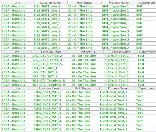
- Physical Location: This location is specific to the physical placement of the data collector on the production floor. It shares the same process name as Logical Location but is unique to a specific device. A Physical Location sharing the process name with the Logical Location will receive units from it and pass to another Logical Location in a Route by Process configuration.
As a general rule, Physical Locations are not uses for routing purposes in Route by Process configurations. If Route by Process is not used, each scanning location must be defined in the route.
When defining Physical Locations, the first four characters are unique, followed by a space or underscore, then character positions six through nine should contain the first four characters of the Logical Location assigned the same process name. The remaining characters provide a brief description of the physical location of the device. This naming convention allows easy filtering in the location table, as the user only needs to filter the Logical Location name, and any Physical Locations with the same process name are returned.
Figure 3: Physical Location Examples:
- Multi-Pass Device Location: A secondary name for a Data Collector Location when it is used for multiple functions. Multi-Pass Devices are used when a product is going to be scanned at the same Data Collector more than once for multiple processes. Reference the section on Data Collector Maintenance for more information on configuring Multi-Pass Devices.
Early on, these types of locations were defined by an alphanumeric character other than the one used by the Data Collection Location, followed by the same three numeric characters, space, then the remaining characters are the process name. For example, if the Data Collector Location is S001, the Multi-Pass Location names assigned to that device number would be A001, B001, C001, and so forth. This is not intuitive to the operator as this name convention does not positively identify the process a unit passes or fails to. Therefore, the newer Physical Location naming convention mentioned previously has been developed.
List Locations
Based on the actual Shop Floor Configuration, the application displays a list with all Locations.
To list locations, select Location Maintenance from the Shop Floor Configuration page.
The Location List page is displayed:
Figure 4: Location List
Following the unit status (see Appendix A), the line of the data collector list is displayed in the different colors as below:
Status = 20 On the Line with process name: green
Status = 28 On The Line Holdwith process name: dark green
Status = 20 On The Line without process name: orange
Status = 28 On The Line Hold without process name: dark orange
Status = 25 In Repair: red
Status = 26 Outside Processing: green
Status = 27 In Repair Outside: dark red
Status = 29 In Repair Hold: dark rose
Status = 30 Finished: blue
Status = 50 Killed: gray
Other Status: black
Note: Location Type = Repair only if it Unit Status is:
25 In Repair: red
27 In Repair Outside: dark red
or 29 In Repair Hold: dark rose
From this screen, the user can view a list of locations, as well as, add, edit, or delete locations.
Add Location
This functionality enables the user to add a location to the Locations Table. All mandatory fields must be populated or error messages are displayed.
Note: When a new Data Collector Location is created, a prompt is displayed to create a record in the Data Collector Table also.
1. To add locations, select Add from the Location Filter main screen.
Figure 5: Add Location
The Location Form is displayed:
2. Populate the mandatory fields;
Shop Floor ID: Each Location record must be attached to a Shop Floor ID.
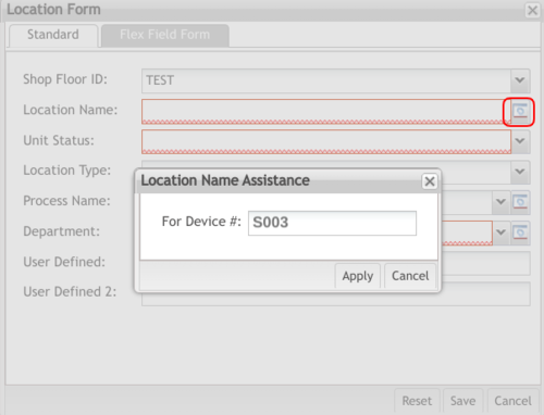
Location Name: Each location must have a unique name. The name can be up to 20 characters: the first four characters must be unique and be followed by a space or underscore. The remaining 15 characters are used to describe the function or physical location. Note the icon adjacent to the Location Name field opens the Location Name Assistance window. This functionality is used when the base34 generic attribute is active. The functionality is used to assist in the operation of generating an S location based on a device code without the user having to know the base34 logic. For example, if a user enters 1000 into the field, the system will then translate that to the respective base34 location name S00A.
Figure 6: Location Name Assistance
Unit Status: Defines the status of a unit based on the status of the Location.
| On the Line | Used at any Location that is a part of the normal manufacturing process or product flow. |
| On the Line Hold |
Same as On the Line with the added ability to allow the unit to move from one SFDC PC to another within the same database. Also used to move from one route to another. When a unit has this status, the Serial record is removed from the SFDC PC and stored on the MES server. It does not appear as part of the SFDC Work-In- Process report, but on the MDS Work-In-Process report. |
| In Repair | Used at any Location that is not considered part of the normal manufacturing process. In creating Routes, any unit with a defect is failed to a Location with an In Repair status. The unit continues to have this status until all defects are repaired. A unit cannot be manually moved from a Data Collection Location with an In Repair status to a Location with On the Line status. Nor can a unit pass from this status to a Finished status. |
| In Repair Hold |
Combines the In Repair status with the secondary functions of the On-Line Hold status. |
| Finished | Defines the unit as complete. Unless the product will be installed into an upper-level assembly, the Route ends by passing a unit to a Location with a Finished status. When a unit passes to a Finished Location, the Serial record is removed from the Current Serial records on the SFDC PC and is stored in History. If a unit is manually moved to a Finished Location from the SFDC PC, the Serial record is moved from Current to History at the next shift change. Neither Shop Floor nor MES Work-In- Process reports include Finished status Locations. |
For more information, see Appendix A. Unit Status Definitions.
Location Type: Kitting_Consolidation, Integration, Inspection, and Repair
Process Name: Defines the manufacturing process occurring at the Data Collection Location. It is used to group multiple Locations with the same function for SFDC and MES reports. The Process Name is used to determine the number of times a unit passes through a Data Collection Location. It also supports SPC/SQC reports grouping the same function locations across multiple lines.
Note: To access Process Maintenance, select the Manage button.
Department: Defines the department that a location is assigned. Supports SPC/SQC reports across multiple Lines. All Locations must be assigned to a Department. The SOMS system uses the department to define the line in which a location is associated.
Note: To access Department Maintenance, click the Manage button.
User-Defined: Provides additional information about the Location. Also links Locations together for SPC/SQC or Reports applications. This is a 20-character text string. The SOMS system utilizes User Defined 1 as the Site Code.
Flex Field Form
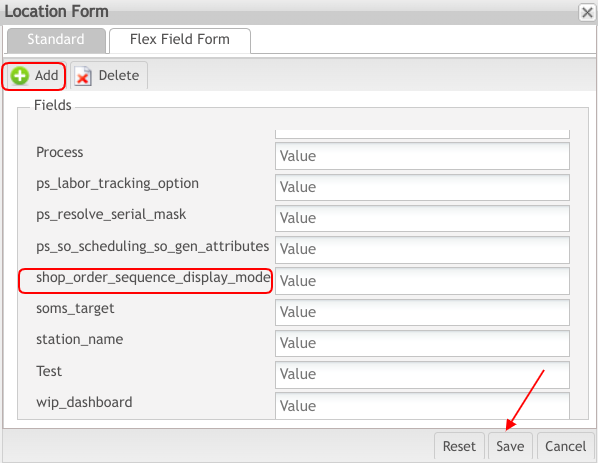
The Flex Field Tab is used for adding and deleting custom information to various elements. The purpose of adding information into the flex field is that it allows users to retain information for later use (e.g., label printing). To use the functionality follow the next steps:
- Select the Flex Field Form Tab from the Location Form. Two types of lists will be displayed—AttributeName and Value.
- Next to the attribute name shop_order_sequence_display_mode you will see a Value field, enter one of the following values:
- SEQUENCED_ONLY: Shows all shop orders assigned to the manufacturing line belonging to the selected location.
- SEQUENCED_AND_FIFO: Shows the first 6 shop orders assigned to the manufacturing line belonging to the selected location.
- Select Save to keep the information, Reset to clear any information that was entered, or Cancel to abort.
Figure 7: Flex Form Field
Basic Maintenance - Departments
This functionality enables the user to manage Department names. Each location will be assigned to a department.
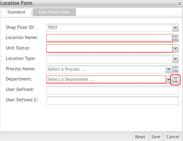
1. To access Department Maintenance, select Add Location or Location, then select the Manage button for theDepartment field.
Figure 8: Add Location - Location Form
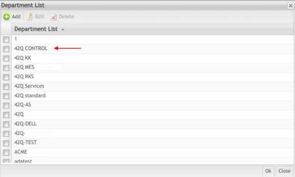
The maintenance page for the Department displays:
Figure 9: Department - Select a Department
Based on the actual Shop Floor Configuration, the application displays a list of all available departments. From this screen, the user can list, add, edit, and delete Departments.
Add Department
This functionality enables users to add or create Departments in the database.
1. To add a Department, select Add.
2. Enter the Department name.Select OK to add/create the Department, or Close to cancel the operation.
The new Department is created and is displayed in the department list, making it available to select.The Create Department screen is displayed:
Figure 10: Create Department
Edit Department
This functionality enables users to update an existing Department name.
Note: Once a department name has been defined, it is normally never changed. Be aware that modifying department names will impact historical reporting; therefore care should be taken when performing a modification.
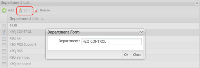
1. To edit the department name, select the Department to edit then select Edit.
The Edit Department page is displayed:
Figure 11: Edit Department
2. Perform the desired edit to the Department name.
3. Select Ok to confirm or Close to cancel the operation. The Department's name is updated and ready for use.
Delete Departments
This functionality enables the user to delete the selected department.
Note: It is not possible to delete a department if the activity has been recorded at a location while it was associated with it. It is also not possible to delete a department if it is associated with a location.
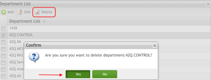
- To delete a department name, select the Department, then select Delete. A confirmation message is displayed.
- Select Yes to confirm or No to cancel the action. The Department is deleted.
Figure 13: Confirm
Process Maintenance
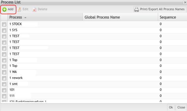
Process Maintenance can be found in multiple modules, for example; Attribute Def Maintenance and Locations Maintenance modules. The functionality is to Add, Edit, Delete, and Print Process Names in the database.
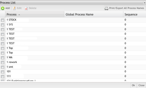
1. To access the Process Maintenance table, select the Manage button for Process where applicable.
The Process List page is displayed:
Figure 13: Process List
Based on the actual Shop Floor Configuration, the list of available Process Names is displayed. From this screen, it is possible to List, Edit, Delete, and Print/Export process names.
Add/Create Process Name
This functionality enables users to add or create Process Names in the database.
1. To add/create a Process Name, select Add.
Figure 14: Process Name - Add
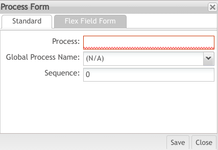
The Create Process pop-up is displayed:
Figure 15: Process Name – Create Process Form
2. Enter the new Process Name;
As a general rule, Process Names should be clear and intuitive. This avoids the risk of confusion comprehending the process by users and operators.
3. Global Process Name: The process name for which the location will be executed.
Is another level to group factory local processes to produce global reports, for example, customer X manufactures the same product in 2 different factories, the factories just need to map all their processes to a global process name for grouping, the result is a global report global processes are default and can not be modified.
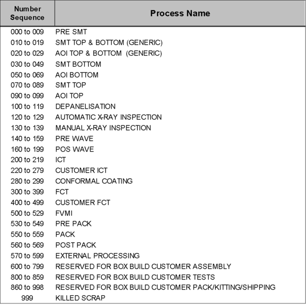
4. Enter Sequence Number. This is an optional field for use with the SOMS.
Generally, each plant will create a sequencing scheme that fits the business requirements. For example, one plant may only have sequence numbers for PCBA processes, while another plant for Box Build processes.
The sequencing scheme should follow the production flow. For example. The process sequence for SMT_Inspection_1 would be lower than the process sequence for Functional_Test_1 as SMT processes occur before testing processes. The Process Sequence conforms to SOMS requirements. The sequencing will aid in SOMS reporting as the processes will display in the sequential order of the product flow. Process Sequencing also aids in grouping common Process Names.
Figure 17: Process Name Sequencing
See Flex Field Form section for further information.
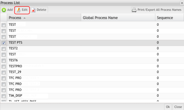
Edit Process Name
This functionality enables users to edit an existing Process Name in the database.
1. Select the Process Name to be edited and then select Edit.
Figure 18: Process Name - Edit
The Edit Process form is displayed:
Figure 19: Edit Process Name
2. Edit Process Name as desired.
3. Select Save to confirm or Cancel to exit.
Delete Process Name
This functionality enables users to delete an existing Process Name, provided there have not been any activity records recorded against it.
1. Access Process Maintenance table by selecting the Manage button for Process where applicable.
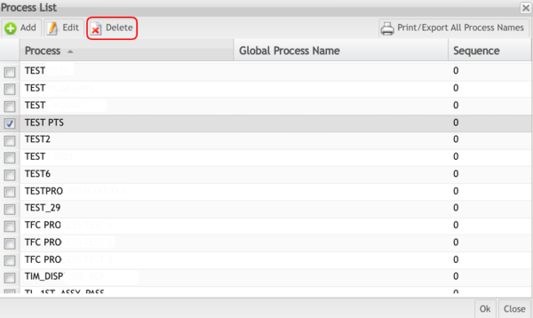
2. Select the Process Name to be deleted then select Delete. A confirmation message is displayed
Figure 20: Process Name - Delete
3. Select Yes to confirm or No to cancel the action.
Print/Export Process Name
This functionality enables the user to print and/or export Process Names.
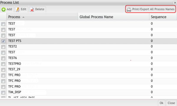
1. To print the Process Names, select Print/Export All Process Names from the Process List.
Figure 21: Process Name - Print
Select on Print to print the report results.A PDF report is generated. A download pop-up window will appear onto the user's desktop.
Edit Location
This functionality enables users to modify or update an existing Location.
Note: Once a location name has been defined, it is normally never changed. Be aware that modifying location names will impact historical reporting; therefore, care should be taken when performing a modification.
1. To edit a Location, select the Location to edit, then select the Edit button in the list.
Figure 24: Location List - Edit
2. Make desired updates in the Location form and select Save to confirm the updates. Select Cancel to cancel the update action.
Copy Location
This functionality enables users to Copy a selected Location.
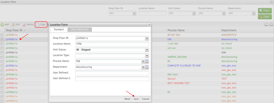
1. To copy a Location, select the Location to copy, then select Copy.
Figure 25: Location List - Copy
2. Select the Shop Floor ID and fill in the necessary fields.
3. Select Save to confirm, Cancel to exit, or Reset to clear all fields.
Delete Location
This functionality enables the user to delete an existing Location from the database
Note: It is not possible to delete a location if activity records have been recorded for the location.
1. To delete a location, select the location, then select Delete.
Figure 26: Location List - Delete
2. Select Yes to confirm or No to cancel the action.The selected Location is deleted from the database.
Location – Where Used List
This functionality enables the user to generate a report displaying the Routes list.
1. To generate the report of where a location is used, click the Where Used List button.
Figure 27: Location List – Where Used
Print/Export Line Locations
This functionality enables the user to print and/or export the current Line Locations. The report results include the Shop Floor ID, Location Name, Unit Status, Process, Department, and User Defined of the selected Line. The report prints on the default printer for the workstation.
1. To print Line Locations, select the Print/Export Line Location option in the Location Filter main screen. The Choose Shop Floor ID pop-up is displayed:
Figure 29: Print Line Locations
2. Choose a Shop Floor ID. A report is generated and automatically downloaded onto the user's desktop.
Print/Export Filtered Locations
This functionality enables the user to print and/or export the filtered Locations. The report results include the Shop Floor ID, Location Name, Unit Status, Process, Department, and User Defined of filtered Locations. The report prints to the default printer for the workstation.
1. To print filtered locations, select the Print/Export Filtered Location option in the Location Filter main screen.
Figure 31: Filtered Location Report
A report is automatically generated and donwloaded onto the user's desktop.
Appendix A
Unit Status Definitions
The following table provides a list of available unit status settings and their definitions (if available). See Locations Maintenance for more information.
| On the Line (20) | Used at any location that is a part of the normal manufacturing process or product flow. |
| In Repair (25) | Used at any location that is not considered part of the normal manufacturing process. In creating routes, any unit with a defect is failed to a location with an In Repairstatus. Unless overridden by an Options setting in Setup Data Editor, the unit continues to have this status until all defects are repaired. A unit can not be manually moved from a DataCollection Location with an InRepair status to a location with On the Line status. A unit cannot pass from this status to a Finished status. |
| On the Line Hold (28) | Same as On the Line with the added ability to allow the unit to move from one SFDC PC to another within the same database. Also used to move from one route to another. When a unit has this status, the serial record is removed from the SFDC PC and stored on the plant server. It does not appear as part of the SFDC Work-In-Process report, but it does appear on the MES WIP report. This location behavior can be overridden by an Options setting in Setup Data Editor. |
| In Repair Hold (29) | Combines the In Repair status with the secondary functions of the On-Line Hold status. |
| Finished (30) | Defines the unit as complete. Unless the product will be installed into an upper-level assembly, the route ends by passing a unit to a location with a Finished status. When a unit passes to Finished, the serial record is removed from the current serial records on the SFDC PC and is stored in history. If a unit is manually moved to a Finished location from the SFDC PC, the serial record is moved from current to history at the next shift change. Neither SFDC nor MES WIP reports include Finished status locations. |
| Container Open (34) | |
| Pulled (55) | |
| Unit Component (60) | Defines a unit when it is a tracked component and has not been properly removed from the Top Level assembly. Requires a special Option line to be scanned again. |
| Unit Old ID (62) | Defines a serial number that was changed to another serial number. |
| Unit Skeleton (64) | Defines a unit serial number used for temporary copies of a real serial number. |


