Configuration
Contents
- 1 SFDC Configuration
- 2 Kit Verify Configuration
- 3 Multi-Level Container Configuration
- 3.1 Container List
- 3.2 Filter Settings
- 3.3 Edit Container Configuration
- 3.4 Copy Container Configuration
- 3.5 Delete Container Configuration
- 3.6 View Container Configuration
- 3.7 Print/Export Container Configuration
- 3.8 Container Task Panel
- 3.9 Create Container Configuration: Level 99 (LOT) /Level 100 (Container)
- 3.10 Create Multi-Level Configuration Containers: Type > 100
- 3.11 Print/Export All Filtered Container Configuration
- 4 Employee Validation
- 5 1. Employee Validation Setup
- 6 SQC Configuration
- 7 Labor Tracking Maintenance
- 8 Algorithm Tool
- 9 MDS Labels
SFDC Configuration
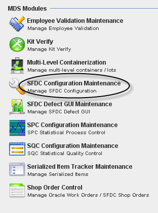
1. To access the SFDC Configuration module, click on SFDC Configuration in the main MDS Modules window.
Figure 1: MDS Client Modules – SFDC Configuration Maintenance
GENERAL NOTES: a)A user only has access to the modules assigned to his/her profile. Profile permissions are granted in the MDS PRAC (Program Access Control) Module by the Program Admin user.
b)Any/all reports printed from jMDS modules will print to the default printer for the workstation.
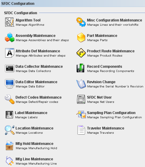
2. The SFDC Configuration main window is displayed.
Figure 2: SFDC Configuration Modules
This is the main SFDC Configuration Module window.
Kit Verify Configuration
The Kit Verify consolidates or validates all of component that we have in a “Kit” that warehouse give to the floor versus the shop order, in order to know if we have missing component in the Kit.
This module is integrated to MDS Client Application and will be available to all Sanmina's Plants.
Layout Configuration
The function of this interface is to allow the user to Add, Copy or Edit an assembly layout in the Kit Verify MDS Database.
Note 1: If Oracle does not send the reference Designator information to MDS the system will allow entering it manually.
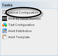
To access the Layout functionality, click on Layout Configuration at Tasks panel.
Figure 4: Choose Layout Configuration
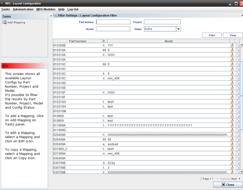
The Layout main window displays:
Figure 5: Layout Configuration Main Window
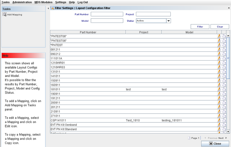
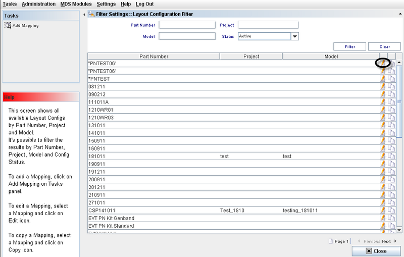
This screen will display all available Layout Configurations by Part Number, Project and Model.
Layout Configuration List
This screen displays all Layouts available and the user can edit or use the copy function.
Figure 6: Layout Configuration Filter
Adding a Mapping (Layout configuration)
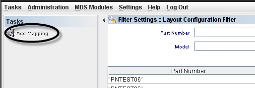
To create a Control Config, the user must to click onCreate Control Config on Tasks panel.
Figure 7: Add Mapping from Tasks panel
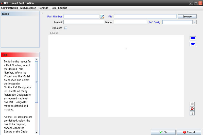
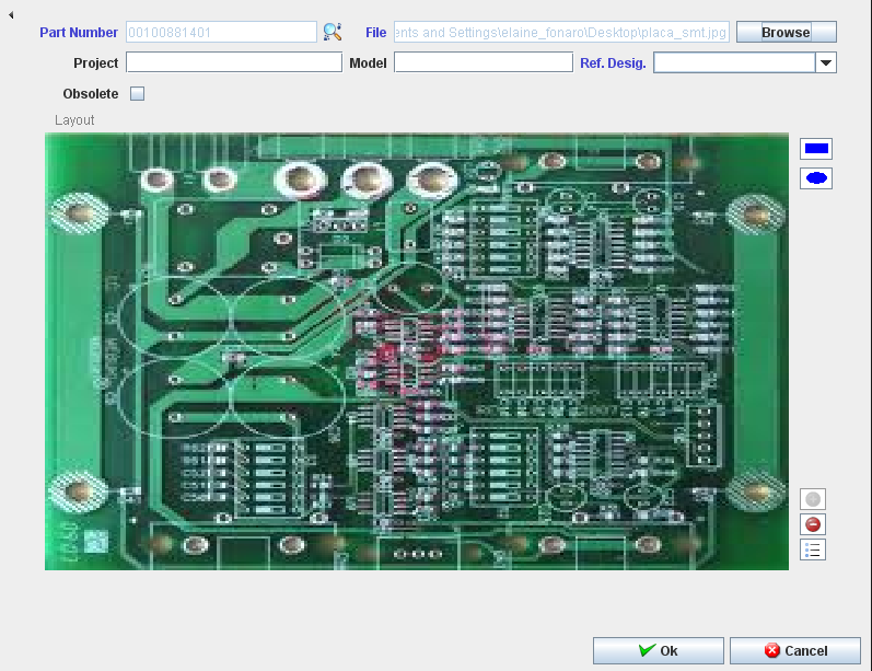
The Layout Configuration screen displays:
Figure 8: Layout Configuration screen
Note1: at least one Ref. Designator must be defined and mapped.
Fields that User can enter/select:
- Part Number;
- File
- Project;
- Model;
- Reference Designator;
- Browse to find the layout file;
Follow the steps below to define a layout for a part number:
- Select the desired Part Number; inform the Project and the Model as needed.
- Click on the “Browse” button to select the new assembly layout. The system will show the File Dialog window and the user can select the image. The system disables the button and the path text box and the image will appear in the layout box;
- On the Ref. Designator list, the user must to create as many Reference Designators as required which will then automatically appear as disabled;
- The user has to click in Square orCircle form Button and draw a Square or Rectangle in Layout;
- Click on the Add “+” button.
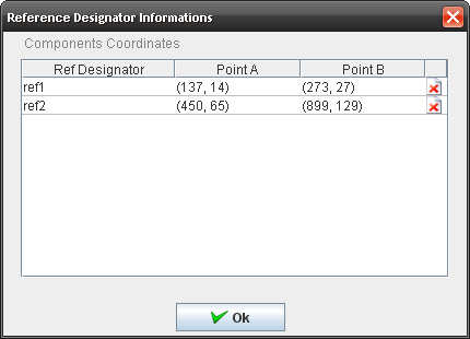
- At the same time a new row with the reference designator information will appear in the “UI control” box with the following variables:
Figure 9: Components Designator
To view the Reference Designator Information, click on the View button in the Layout Configuration window.
a.X coordinate;
b.Y coordinate;
c.Width;
d.Height;
- To delete the component, click on Delete icon.
- After adding all reference designators the user has to click on the “OK” button and the system will insert all these rows into the MDS Database;
Editing a Layout Configuration
Figure 10: Edit Layout configuration
To edit a Mapping, the user must to select a Mapping and click on Edit icon.
The Layout Configuration window displays with the existing layout information.
Figure 11: Layout Configuration
Note that the following fields can not be updated:
- Part Number
- Layout
- Project
- Model.
The Ref Designator can be removed from the list or included in the list.
To obsolete a configuration, check the Obsolete box.
Copying a Layout Configuration (mapping)
This option allows the user to create a new layout based on a pre existing layout (this module allows the user to copy and modify an existing assembly layout).
Follow the steps bellow to copy a layout:
- The user must create a new relation between the project and the model;
- Select the layout in the list and click the “Copy” button;
- The image will appear in the layout box, and all records will appear in the “UI control” grid;
- Select the part number that will have the layout chosen;
- In case the user wants to change any reference designator he/she has to select it on the assembly layout and the reference designator row that was selected will appear in the “UI control” grid.;
- Once the modification has been finished, the user has to click onOK button;
The system updates the information into the MDS database.
Test Configuration
Figure 25: Test Configuration window
This screen shows all Test Configurations.
Performing Searches
To perform searches, there are there are just one field available:
Filters Fields:
- Part Number;
- Test Configuration Name
- Top Level Assembly
- Location
Enter the information and click on Filter.
To clear the filter fields, click on Clear.
Adding/Editing Test Configuration;
See bellow the Add/Edit steps.
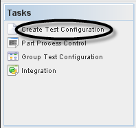
1. To add a Test Config, the user must to click on Add Test Config on Tasks panel.
Figure 26: Create Test Configuration
2. To edit or delete a Test Config, the user must to select the config in Test Config List and click on Edit or Delete icon.
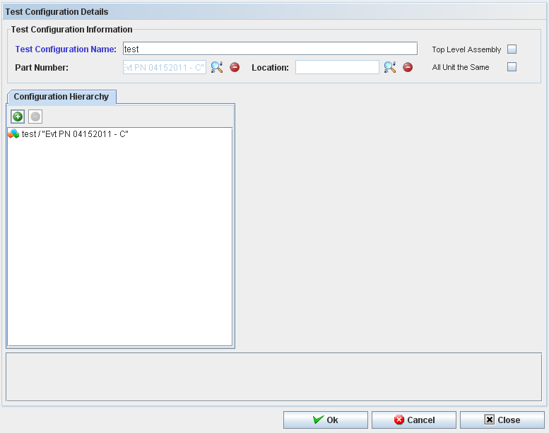
3. Click on Create Test Configuration in the Tasks Panel. The Create Test Configuration window displays.
Figure 27: Test Configuration Details
To add a test configuration, the user must to follow the following steps:
1. To create or edit a test configuration it's required to inform the top level Part Number.
2. To add a part number, a test configuration or a test configuration group to the test configuration, click on the "+" icon.
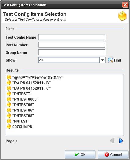
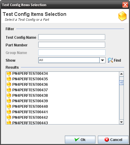
3. The Test Configuration Items Selection popup displays.
Figure 28: Test Config Items Selection
4. The user must enter a search item (your criteria: Part Number only, a Test Configuration Group or a Test Configuration only) and click on Find.
5. Double click on the result.
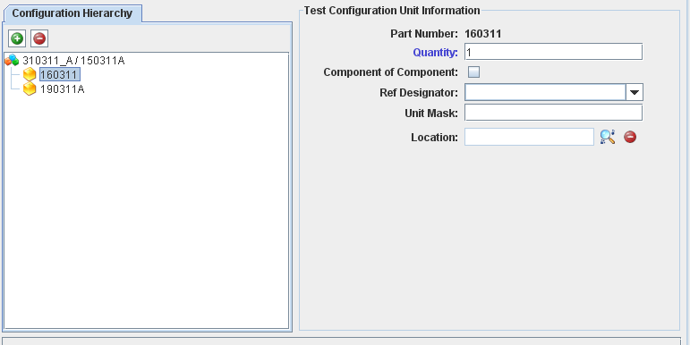
6. Fill mandatory fields (part number and quantity) in "Test Configuration Unit Information".
Figure 29: Test Configuration Details
7. Click on Ok button.
Note1: Obsolete Part Numbers do not display. The Part Number chosen will display in "Configuration Hierarchy".
The user can see the "Test Configuration Selection" window with "Test Configuration", "Part Number" and "Test Config Group"
Note2: It's possible to add more than one Test Configuration, Part Number or Test Config Group to create a Test Configuration.
8. The information is saved in the database.
9. The "Test Configuration" window closes and the Test Configuration created is displayed.
10. To delete a part number, a test configuration or a test configuration group from the control configuration, the user must select the item and click on the "-" icon.
Part Process Control;
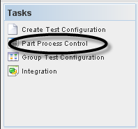
To manage Part Process Control, the user must to click on Part Process Control on Tasks panel.
Figure 30: Selecting Part Process Control
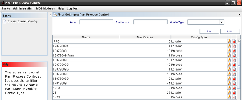
The Part Process control Window displays.
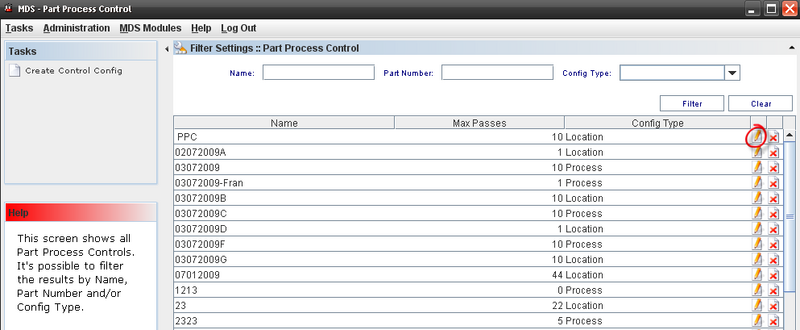
Figure 31: Part Process Control
This screen displays all Part Process Control available.
Editing or Deleting from Part Process Control List
Figure 32: Editing a configuration from Part Process Control List
To Edit a Control Config, the user must to click on edit icon in the list.
The edit page displays:
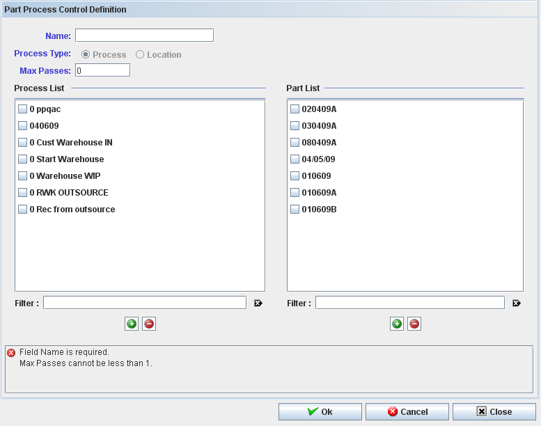
Figure 33: Part Process Control definition
Toupdate a part process control config it is required that the user type a unique name, the config type (process or location) and the max passes.
Note: All items of the control must be of the same type: process OR location.
At least one process or one location is required; the part number list is optional information.
To add a process or a location to the control config:
1. Click on the "+" icon below Process/Location list.
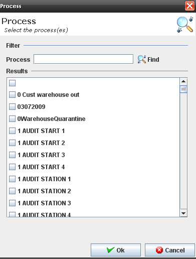
2. The Process popup displays:
Figure 34: Process Popup
3. Execute the filer to select an available process.
4. Click on OK button.
5. The selected process must display at the process list.
To delete a process or a location from the control config, select the process or location and click on the "-" icon below Process/Location list.
Click on Ok to confirm.
To add a part number to the control config, the steps are the same to add process:
1. Click on the "+" icon belowPart list.
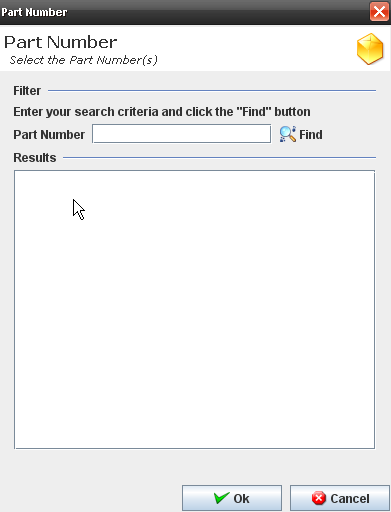
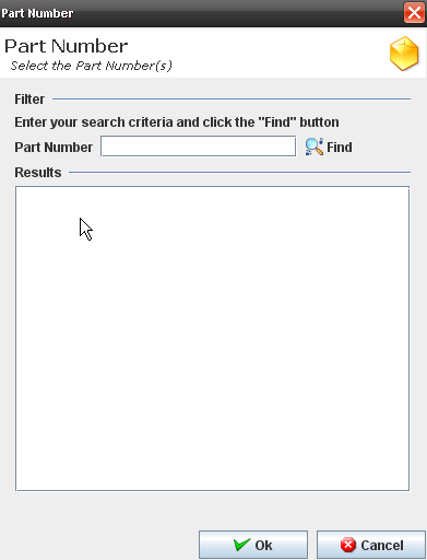
2. The part Popup displays:
Figure 35: Part Number dialog
3. Execute the filer to select an available part number.
4. Click on OK button.
The selected part must display at the process list.
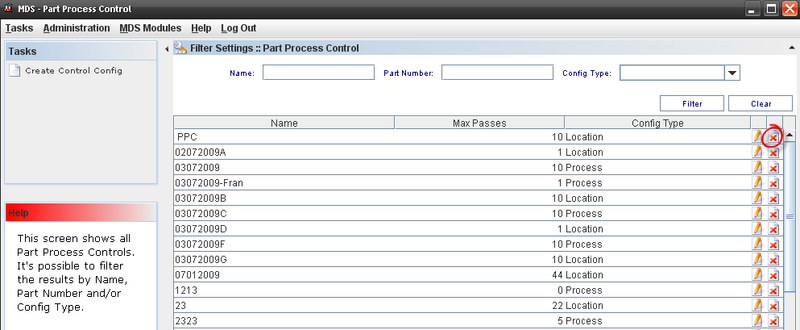
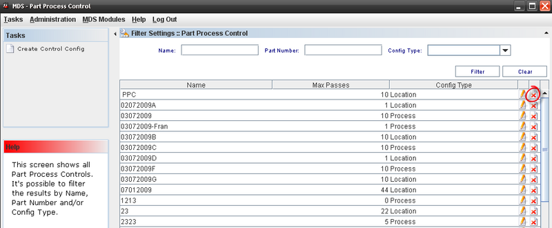
Figure 36: Deleting from Part Process Control List
To delete a Control Config, select the control and click on Delete icon in the main Part Process Control list window.
Click on Ok to confirm.
Creating a Control Configuration
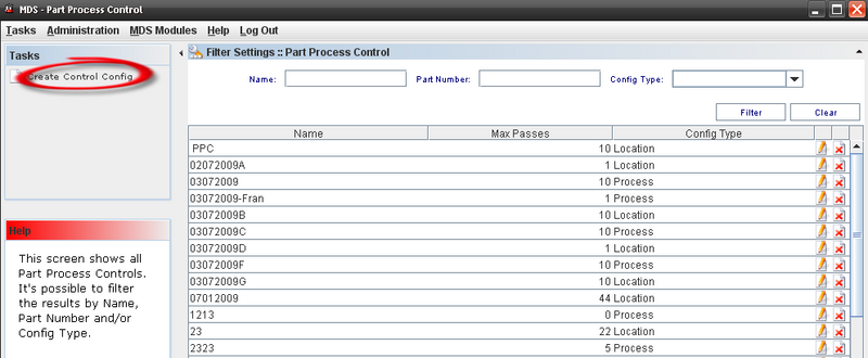
To create a Control Config, the user must to click onCreate Control Config on Tasks panel.
Figure 37: Create a Control Config
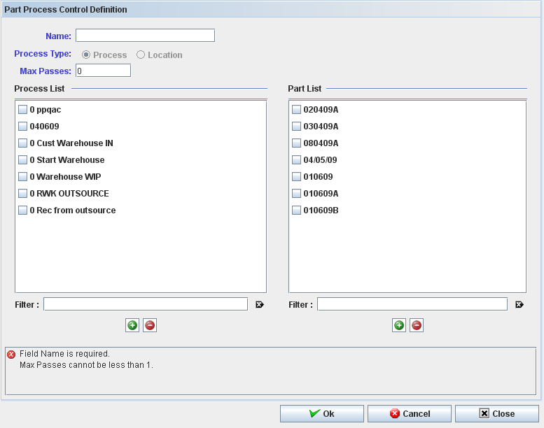
The Part Process Control Definition displays:
Figure 38: Part Process Control Definition
To create or edit a part process control config it is required to the user informs:
- Name;
- Config Type and
- Max Passes.
Note: All items of the control must be of the same type: process OR location.
At least one process or one location is required; the part number list is optional information.
To add a process or a location to the control config:
1. Click on the "+" icon below Process/Location list.
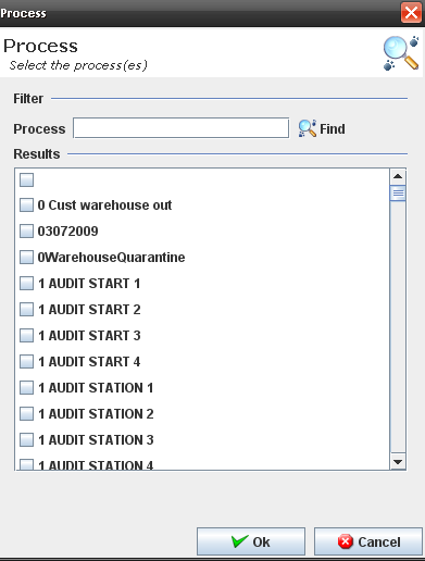
2. The process Popup displays:
Figure 39: Process Popup
3. Execute the filer to select an available process.
4. Click on OK button.
5. The selected process must display at the process list.
To delete a process or a location from the control config, select the process or location and click on the "-" icon below Process/Location list and click on Ok to confirm.
To add a part number to the control config, the steps are the same to add process:
1. Click on the "+" icon below Part list.
The part Popup displays:
Figure 40: Part Number
2. Execute the filer to select an available part number. 3. Click on OK button. 4. The selected part must display at the process list.
To delete a part number from the control config, select the part number and click on the "-" icon below Part list.
Figure 41: Deleting Control Config from Part Process Control List
To delete a Control Config, select the control and click on Delete icon in the main Part Process Control list window and click on Ok to confirm.
Group Test Configuration;
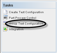
To manage Groups Test Config, the user must to click on Group Test Configuration on Tasks panel.
Figure 42: Test Configuration
To access the Group Test Config, click on Group Test Configuration in the Tasks panel.
Figure 43: Group Test Configuration List Filter
Sorting Colum
The application allows to sort all columns of the list (ascending or descending), including the multi-column sorting keeping the "control" key pressed.
Adding a Test Config Group
Figure 44: Adding Test Config Group
To add a Group, click on Add Test Config Group on Tasks panel.
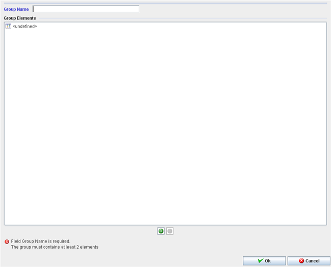
The Test Config Group window displays:
Figure 45: Adding Test Config Group
To create or edit a test config will be required to the user informs:
- Group Name;
To create or edit a test config group it will be required to the user to inform a unique group name.
All items of the group must be of the same type: test config OR part number.
To add a test config or a part number to the group:
1. Enter the new group name and click on the "+" icon.
2. The Test Config Items popup displays:
Figure 46: Config Items Popup
3. Execute the filter to select an available Test Config or part number.
4. Click on OK button.
5. The selected test config or part number must display at the group name element list.
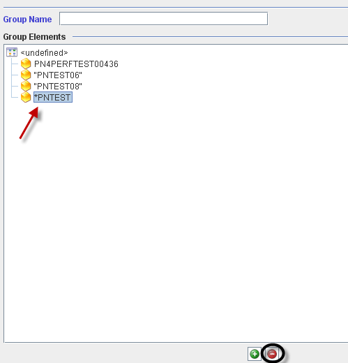
To delete a test config or a part number from the group, the user must to select the test config or the part number and click on the "-" icon.
Figure 47: Deleting Group Elements
Click on Ok to confirm.
Editing a group name.
Figure 48: Deleting Group Elements
To edit a group, select the group and click on Edit icon.
The same window to create a group displays. The user is able to change the group name or add/delete part numbers/test groups clicking on “+” icon to add or “-” icon to delete.
For more information, see the topic [#_Adding_a_Test 2.8.4.2 - Adding a Test Config Group].
Deleting a group name.
Figure 49: Deleting Group Names
To delete a Group, select the group and click on Delete icon.
Click on Ok to confirm.
Integration
To integrate a Top Assembly, scan or type the Component Serial Number according to the requested Ref. Designator.
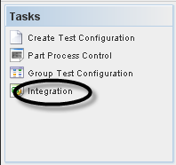
To integrate a Test Config, the user must to click on Integration on Tasks panel.
Figure 50: Test Configuration - Integration
Finding Top Assemblies to Integrate
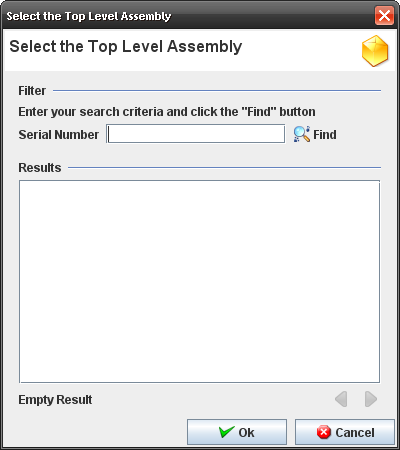
When the user clicks on "Integration" from Tasks panel, the screen to find and select the top assembly to integrate components is displayed.
Figure 51: Select the Top Assembly
Follow the steps below:
- Go to Kit Verify Test Configuration Integration, leave the Serial Number field empty or enter a S/N and click on Filter.
Note: Only top assembly serial numbers in status >=20 which have a test configuration created for the main part number must be displayed. The paginator buttons (previous and next) are displayed and 10 serial numbers are displayed per page.
Showing Integration Information
Figure 52: Integration Information
Follow the steps below:
- Go to Kit Verify Test Configuration Integration, fill the Serial Number field with the top assembly;
- Double click on top assembly;
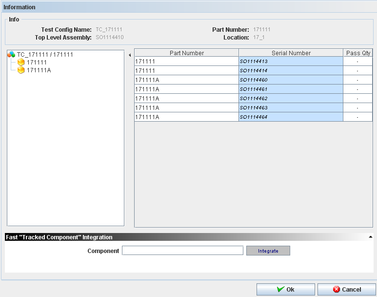
- The test configuration tree view which was created for the main part number is displayed and beside that the components to integrate to the serial numbers are displayed;
- Click on Serial Number for the related part number, fill with one of the serial numbers created according to the pre condition 2 and press enter;
- The serial number is recorded to the part number and the application points to the next serial number to be filled;
- Repeat the step 3 for the remaining serial numbers and click OK;
- The message "Are you sure you want to create a new component integration?" is displayed.
Alert Distribution
To access the Alert Distribution functionality, from Tasks panel, click on Alert Distribution.
Figure 53: Shop Order List
The alert distribution list should be like a profile. We can select the user for each program and these users will receive an email alert base on xml template.
The Alert Distribution list displays:
Figure 54: Alert Distribution
From this screen, the user is able to add, edit, copy or delete alerts distribution. See the next topics for more information.
Adding Alert Distribution
Figure 55: Adding Alert Distribution
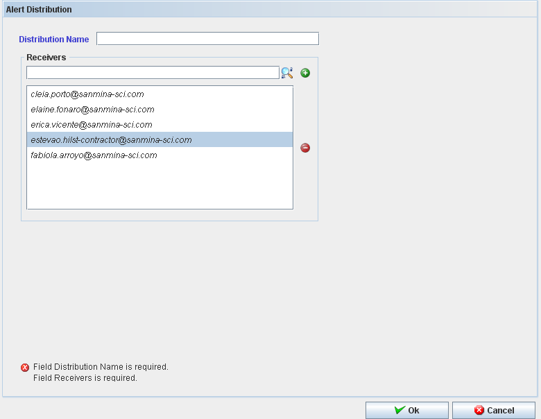
The Add Alert Distribution window displays:
Figure 56: Add Alert Distribution
To add an Alert Distribution, follow the steps bellow:
- In Task Panel click in "Add Alert Distribution" option;
- Fill the mandatory fields (Distribution Name and Receivers);
- Click in "Ok" button;
- Confirm the Alert Distribution creation.
The "Alert Distribution" window closes and the "Alert" is displayed with the recorded "Alert" in the table.
The user can search for receivers. Click on “+” to add or “-” to delete.
Editing Alert Distribution
Figure 57: Editing Alert Distribution.
Follow the steps bellow to edit an alert distribution:
- On the Alert Distribution list, select an existing Alert;
- Click the Edit icon; The Alert Distribution screen displays. It is the same for Add Distribution alert.
- Change the mandatory fields;
- Click "OK" button
- Confirm the Edit.
Copying Alert Distribution
Figure 58: Copying Alert Distribution
The copy feature allows the user to copy alert information. Follow the steps bellow:
- On the Alert Distribution List, select an existing Alert;
- Click the Copy Icon;
- Change the mandatory fields;
- Click "OK" button.
Deleting Alert Distribution
Figure 59: Deleting Alert Distribution
Follow the steps bellow to delete an Alert:
- On the Alert Distribution List, select an existing Alert;
- Click the Delete icon;
- Click "OK" button.
- A confirmation box displays.
- The Alert is deleted.
Multi-Level Container Configuration
This chapter describes how the user manages the Multi-Level Containerization MDS Module. It details all functionalities and actions that can be performed by users.
GENERAL NOTES:
- Most error and informational messages are displayed in a dialog box. Click OK or press Enter to dismiss the dialog window. Yes or No buttons may also be provided to answer questions presented by the message dialog window.
- The user Profile defines what the user can access.
Figure 3: Multi-Level Container Configuration
The user is able to perform actions like create, print/export filtered results, edit, copy, delete, view or print/export containers configuration.
The next topics will describe all available Container Configuration functionalities.
Container List
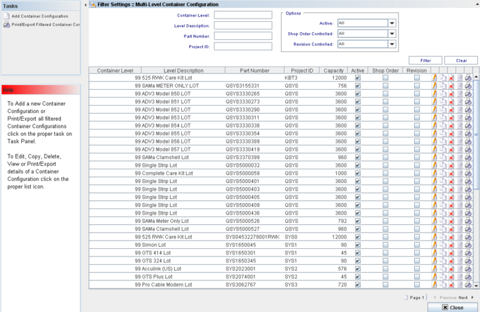
The Container List displays all container levels and allows performing the following actions:
- Filter Data
- Edit a Container Configuration
- Copy a Container Configuration
- View a Container Configuration
- Delete a Container Configuration
- Print/Export details of a Container Configuration.
Note that it is possible to execute two actions from the Task Panel:
- Add a new Container Configuration
- Print/Export all Filtered Container Configurations
Filter Settings
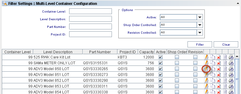
To perform searches, there are four available fields:
Container Level: Predefined container levels are: “99 LOT”, “100 BOX”, “110 SKID” and “120 PALLET”; levels 101-999 are Multi-Level Containers and are handled only by MDS Client.
Level Description: The default description for the level.
Part Number: A number which serves to uniquely identify a part (product).
Project ID: The project identification number.
Also, the user can select additional options from the Options section:
Active (All, No, Yes): NO implies inactive for containerization. Default=YES;
Shop Order controlled (All, No, Yes): YES allows only units from a single shop order to be containerized together. Default=NO;
Revision Controlled (All, No, Yes): YES means only one revision can be containerized together. Please correct and check the default value.
Enter the information or combination of information and click on Find.
Figure 4: Filter Settings
To clear the fields’ contents, click on Clear button to start a new filter.
Edit Container Configuration
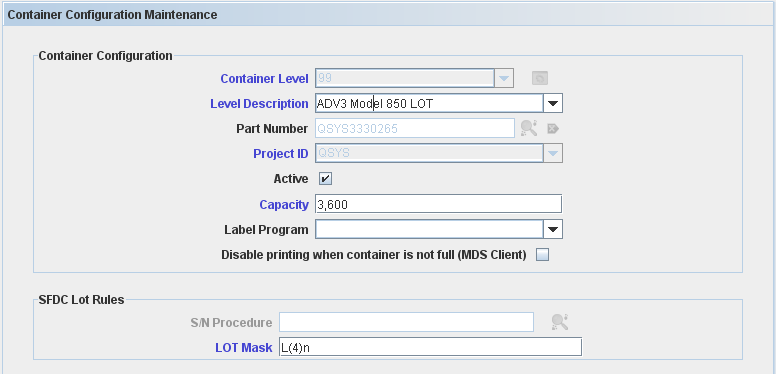
To edit a container configuration, go to MDS Client > Multi-Level Containerization > Container Configuration> Container Configuration list, select an existing Container Configuration and click on Edit Icon.
Figure 5: Multi-Level Container Configuration - Edit
The Container Configuration Maintenance screen displays:
Figure 6: Container Configuration Maintenance - Edit
All the container configuration information is updated according to the updates applied and the container configuration is displayed in the container configuration's list.
Container Level, Part Number and Project ID cannot be edited, as they are the keys of the record.
Note: For more details about a field’s description, see the [#_5.1.2a_Create_Container Create Container Configuration] topic.
Copy Container Configuration
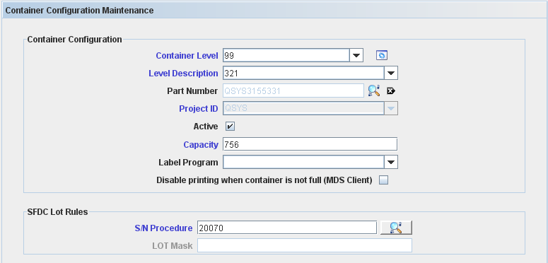
To copy Container Configuration definitions, go to Container Configuration> Container Configuration list, select an existing Container Configuration and click on the Copy icon.
The Container Configuration Maintenance window is displayed:
Figure 7: Container Configuration Maintenance - Copy
Change the necessary information and click on the "Ok" button. The new Container configuration created is displayed on Container Configuration List.
Delete Container Configuration
To delete a container configuration, go to Multi-Level Containerization > Container Configuration> Container Configuration list, select an existing Container Configuration and click on Delete Icon.
Figure 8: Multi-Level Container Configuration - Delete
A confirmation message displays. Click on Yes to confirm the deletion or No to cancel. The Container Configuration will be deleted from the containers list.
View Container Configuration
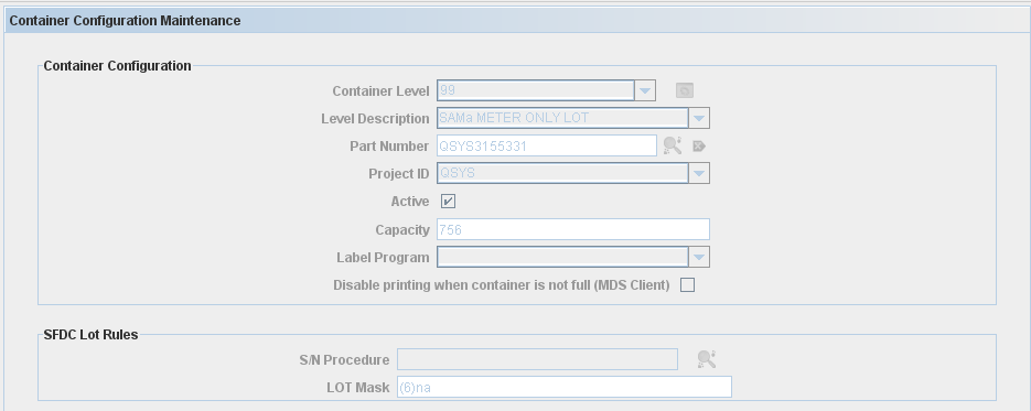
To view the container information, go to Multi-Level Containerization > Container Configuration> Container Configuration list, select an existing Container Configuration and click on the view Icon.
The container configuration maintenance window displays:
Figure 9: View Container Configuration Window
Note: all the fields are read only.
Print/Export Container Configuration
1) To print/export containers, go to Multi-Level Containerization > Container Configuration> Container Configuration list, select an existing Container Configuration and click on the Print/Export Container Configuration Icon.
A report is generated. In the viewer screen, click on "Save" or “Print” button to save or print the report result.
Container Task Panel
From the Task Panel the user is able to create a new container configuration and print/export all filtered container configuration created.
Create Container Configuration: Level 99 (LOT) /Level 100 (Container)
There are different configurations for Containers Level 99 (LOT) and level 100 (Container). See bellow the differences between them.
** Container Level = 99: Configuration
To create a container configuration, go to Multi-Level Containerization > Container Configuration > Task Panel and click on Add Container Configuration.
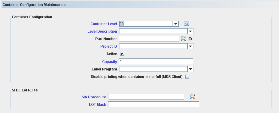
The Container Configuration Maintenance screen is displayed:
Figure 10: Container Configuration Maintenance
Container Configuration fields description:
Container Level: defines the container level (99 to 999) – default is Empty. For this topic, the level used is 99(LOT). The default Container Levels, 99 - LOT, 100 - CONTAINER, 110 - SKID and 120 - PALLET cannot be edited or deleted, it’s created automatically by the application.
SFDC Lot Rules:
- S/N Procedure: not used when Serial Mask is specified. The field can contain either (i) a predefined program filename or (ii) an algorithm number, if the algorithm was defined using the Algorithm Tool – default Empty;
- Lot Mask: not used when Serial Algorithm Procedure is specified. Up to 30 characters in length. The mask of the serial number for the container or lot. Using a serial mask, container serialization schemes can be different per part number – default Empty;
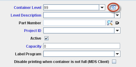
To manage the container levels click on Manage icon:
Figure 11: Container configuration Maintenance
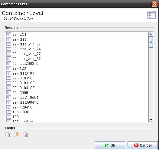
The Manage Level screen is displayed:
Figure 12: Container Level Maintenance
The user is able to Add, Edit or Delete container levels.
Create a new container level
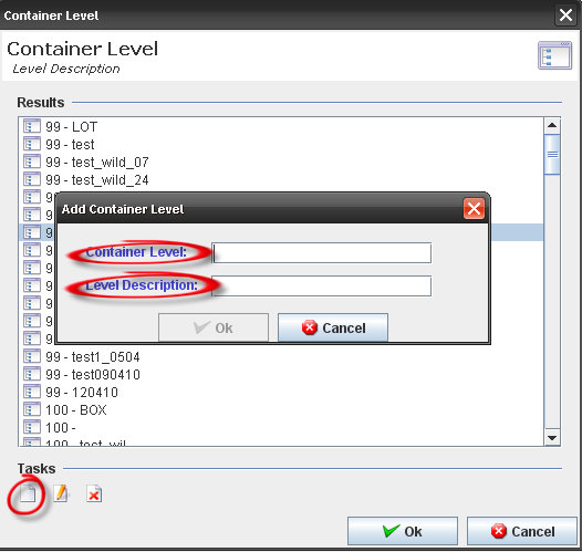
To add a container level, click on the Add icon in the bottom of the window. The Add Container Level window displays.
Figure 13: Container Level - Add
Enter the "Container Level" with a value between 99 to 999 and the "Level Description" with a value that does not exist in the database. Click on OK to finish.
The new container level will be displayed in the containers level list and the user will be able to select it when creating/editing a container configuration.
Edit/delete a container level
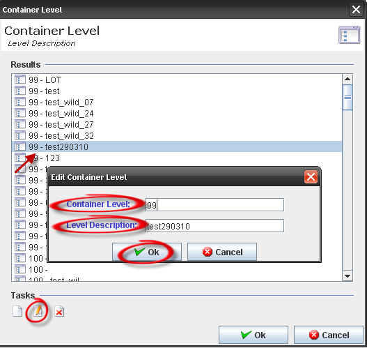
Edit/delete container level: (maintenance button) can be performed at any time except for a default value or a container definition that already exists for that level; otherwise, if there are no definitions, editing or deleting a container level is allowed. Type 99 (LOT) cannot be edited. Also, all types without a container configuration associated can be deleted. If a definition already exists, then the container level cannot be modified.
Figure 14: Container Level – Edit
Figure 15: Container Level - Delete
** Container Level = 100: SFDC Container Rules section
New configuration was added for level 100 and will run just in the MDS Client. Just configuration with algorithm type = Container will run in the SFDC.
It supports the following options:
- Revision Controlled;
- Shop Order Controlled;
- Auto Close;
- Dimensions (MDS Client only);
- Shipping Level
- Multi Part
- S/N Procedure
- Container Mask
General Rules:
After entering all mandatory fields, click on the "OK" button and confirm the configuration creation. The container configuration list is updated with the new container configuration, with the inserted data.
It is necessary to use the same "Level" for all records with the same "Description". For example, if you create a level 120 and say that the name is "Overpack Box", then any other record which is added later that has the description "Overpack Box" needs to be level 120.
Note: The application cannot show obsolete part numbers for selection during the creation of a container configuration.
Create Multi-Level Configuration Containers: Type > 100
To create a new Container Configuration, click on Add Container Configuration button in the task panel.
Figure 16: Add Container Configuration
The Container Configuration Maintenance window is displayed:
Figure 17: Multi-Level Container Configuration Maintenance
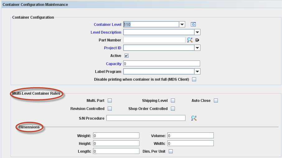
The following fields are displayed just for containers >100: Container Level, Level Description, Part Number, Project ID, Active, Capacity, Label Program and Disable printing when container is not full (checking this option, the container configuration will print only when the container is full).
The following check boxes are displayed as Multi Level Container Rule:
- Revision Controlled: Revision Controlled (All, No, Yes): YES means only one revision can be containerized together. Please correct and check the default value.
- Shop Order Controlled: Yes / No. Yes allows only units from a single shop order to be containerized together – default No;
- Shipping Level: Yes / No. Yes defines that a specific container is the Shipping level of containerization – default No;
- Auto Close: Yes / No – default No;
- S/N Procedure: Show all “COPS Container” algorithms created in Algorithm Tool – default Empty. Not used when Serial Mask is specified. The field can contain either (i) a predefined program filename or (ii) an algorithm number, if the algorithm was defined using the Algorithm Tool – default Empty;
- Multi Part: Allow multiple part number in a container. It is possible to add elements from another part number, but it must have the same Project Id.
In Addition, the user can define the Container dimension filling the weight (kg), height (m), length (m), volume (m3) and width (m). Selecting the Dimension per Unit flag, it is possible to fill for each configuration container. If the dimension is in different measure, the data will be converted.
Print/Export All Filtered Container Configuration
To Print/Export all Filtered Container Configurations, click on Print/Export Container Configurations button in the tasks panel.
A report is generated:
Figure 18: Print All Filtered Container Configuration
The user can perform some actions (print, save, fit page…) by clicking on the buttons in the top of the report.
Employee Validation
1. Employee Validation Setup
This edition applies to MDS14-5 Application (Employee Validation Module) and all subsequent releases and modifications until otherwise indicated in new revisions.
This module is responsible for creating trainings that operators should perform to work in manufacturing processes. The whole operator control (registration and information maintenance) and trainings and certificates required for the operators work in shop floor (mainly in medical plants) will be administered by this feature.
Employee Validation is a manual input module that allows individuals working on the Employee other than those creating a new configuration and maintaining an existing one.
It provides a method of creating employee / password / training records that can be administered by non-SFDC personnel, and a method of identifying specific processes that must be controlled.
It will still support the traditional login methods for data collectors without controlled processes.
To access Employee Validation module, click onEmployee Validation Maintenance in the main MDS page:
Figure 1: MDS Modules
The Employee Validation Maintenance page is displayed as follow:
Figure 2: Employee Validation Maintenance
Employee Validation is composed by sub-modules and these work instructions will help users to understand each one.
- Certificate Maintenance: responsible for manage the certificates as well associate process and process groups to certificates;
- Class Maintenance:
- EV Process Maintenance:
- Employee Maintenance:
- Process Group Maintenance:
Employee Maintenance
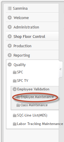
To access Employee Maintenance, click on Employee Maintenance in the employee validation main page.
The first step in setting up Employee Validation is to define all the Employees in the Employee Maintenance module.
Listing employees
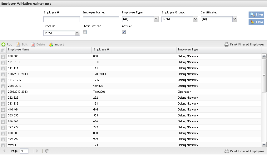
The Employee List displays all employees’ name, type and number and allows filtering data by entering data in the available field, edit employees by clicking on Edit icon and delete employees by clicking on Delete icon;
Figure 3: Employee Maintenance Page
This is the main Employee validation maintenance page and the users are able to perform searches, sort, add, edit, delete, import and print/export employees.
Performing Searches
To perform searches, there are four available fields: Employee #, Employee Name, Employee Type, Employee Group, Certificate, Process and the Active/Show Expired flags.
It’s possible to search by one field or a combination of those. Click on Filter button.
Figure 4: List and Search Employees
The search result is displayed in the Employee list.
Note: It is possible to list only the active employees by checking the Active check box.
Adding Employee
This functionality allows adding employees in the application.
Employee records can be added individually clicking on Add ,or a number of records can be imported clicking on Import button.
To Add Employees, click on Add.
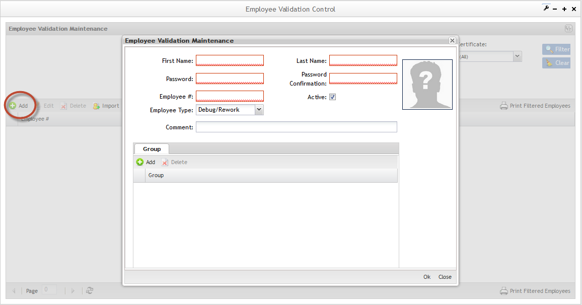
The Employee validation page is displayed:
Figure 5: Adding Employee
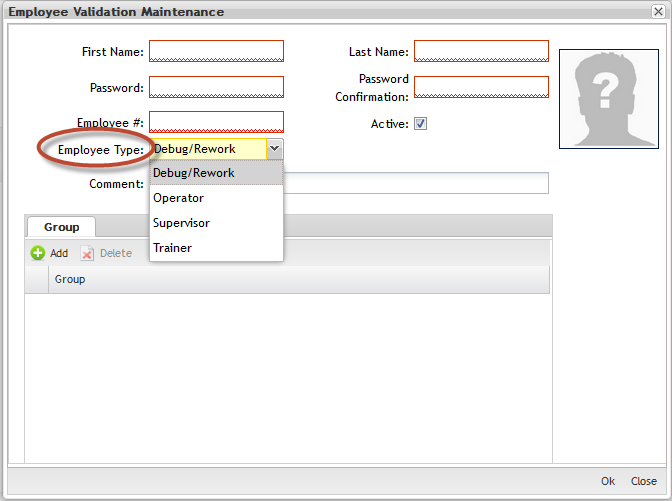
Fill in all mandatory fields (in red):"First Name", "Last Name","Password", "Password Confirmation", "Employee#", "Employee Type" (operator, supervisor or trainer).
- Trainers are the people used to create a class. Someone has to be a designated trainer, in order to create a class in EV. They are also the people typically holding "classes" and performing any hands on training.
- Operators are the production folks who perform work. They either have the certification to perform a job or not. That is the EV control for processes.
- Supervisors are required to be in EV and have at least 1 certificate. They do not necessarily have to be in every certificate in order to be able to scan serial numbers through the processes. Effectively, they are "superusers" which can scan serial numbers through any process, without having the actual certification. They just must have 1 certification for something.
- Debug/Rework are the production folks who perform work with debug/rework roles;
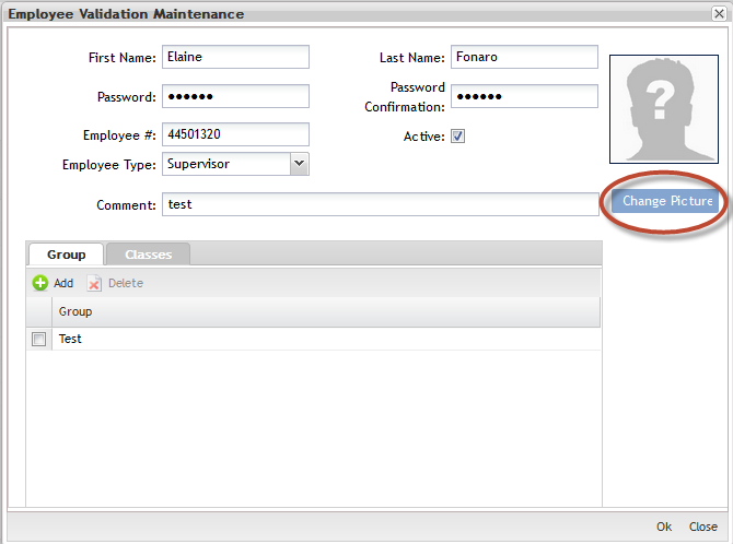
- Click onChange Picture to add the Employee image.
Figure 6: Employee Validation - Employee Type
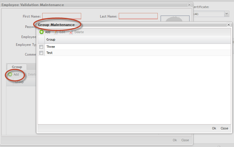
After Employee records have been created, each employee should be associated to at least one Group.
Group Maintenance:
To add, edit, delete and undo groups, go to group maintenance;
1. Click on Maintenance button to open the Groups Maintenance popup.
Figure 7: Groups Maintenance
After insert the employee data, the user is able to upload the employee image, or if prefer, upload the image in the future using the Edit Employee button.
Figure 8: Uploading Employee Image
Click on Yes to continue the upload or No to abort.
Click on Change Picture to upload and save the image.
Importing Employees
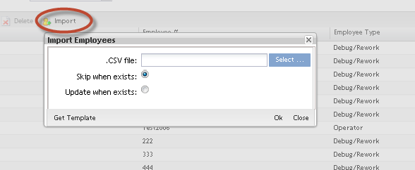
To Import Employees from a CSV file, click on Import.
Figure 9: Import Employees
The Import employee is displayed.
Note: Selecting Skip when exists, the user will not be updated.
This functionality allows importing employees in mass.
The format of the .csv file for importing Employee records is:
| First Name | Last Name | Password | Employee # | Employee Type |
| Character | Character | Character | Character | Character |
After creating the spreadsheet, follow the steps below to import:
- Go toEmployee Maintenance page and click on "Import" button.
- Select the .CSV file already created.
- Click on "OK" button.
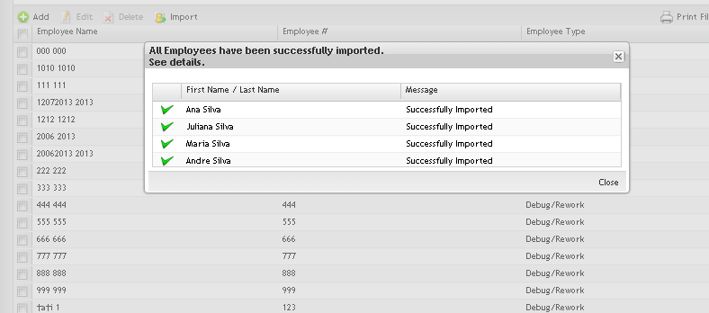
The"Import Employee Results" page with the import results is displayed:
Figure 10: Import Employees
- Click on "Close" button.
After the import process, a report is displayed with the employees successfully imported and with those who failed.
Print Filtered Employees
To Print Filtered Employees list, click on Print Filtered Employees button.
Figure 11: Exporting Employees
A .pdf report is generated with classes, certificates and processes. The user can save it and print.
Editing Employees Information
Figure 12: Editing Employee Information
It is possible to edit the employee information by selecting the employee and clicking on Edit button.
The steps to edit employees are the same as Add Employees. See Add Employee section for more information.
Deleting Employees Information
Delete the employee by selecting the employee and clicking on Delete button.
Figure 13: Deleting Employees
NOTE:
1. The deleted employees will be removed from classes also.
2. The application does not allow removing a Trainer that is assigned to a class.
EV Process Maintenance
The processes are created in the SFDC Maintenance module. In EV, the user is able to Add Processes already created. The added Processes will be processes that EV will download to SFDC and check for Classes. In this step the user is able to add, edit, remove and re-add processes and process groups that will be managed inside the Employee Validation Module.
| To access the EV Processes Maintenance, click on EV Processes Maintenance. |
The Process list main page is displayed.
Listing Process
Figure 14: Processes List
In the Process List, the user can perform a filter by typing the process name in the Filter field. Click on Ok to confirm.
Adding Processes
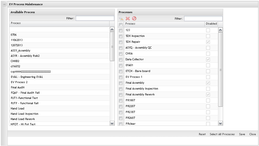
Figure 15: Add Process List
The available processes are displayed to be added in EV.
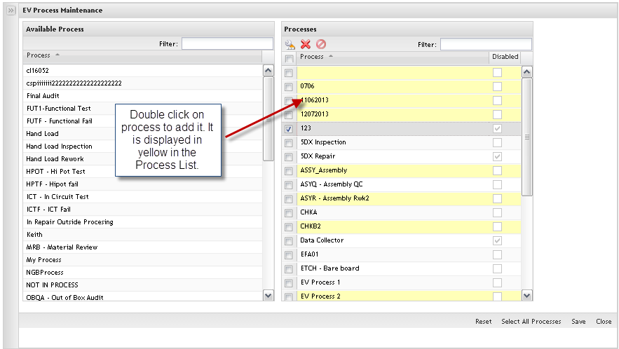
1. To define the processes to be controlled by EV, double click on available process in the left application panel.
2. The new added process is displayed in the Process list highlighted in yellow.
To cancel, click on Reset before save.
To add all processes available, click on Select All Processes. Clicking on Reset
Click on Save to commit the updates.
If there are multiple processes that are to be controlled by Employee Validation, yet fall into the same certification, these processes can be grouped together by defining a Process Group. Click on the Process Group Maintenance module. Follow the steps defined in the Process Group Maintenance topic for specific instructions on how to create Process Groups.
Editing Processes
To Edit (Enable and Disable) Processes, follow the steps bellow:
Figure 16: Edit Processes
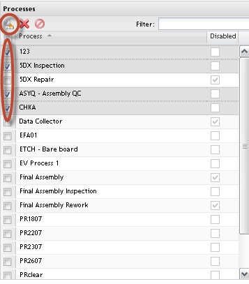
1. Select the process (es) to be updated and click on Enable/Disable icon.
2. Click on Yes to confirm the status change.
Note: The process will be disabled when it is not used, but it can be used anytime by enabling it.
After clicking on the edit icon, the process shows in dark gray. To commit this, click on Save.
Removing Processes
To Remove Processes, follow the steps below:
Figure 17: Remove Processes
1. To Remove Processes from list, select the process and click onRemove button.
Note: If the selected process has any associated certificate(s), the application will not allow the user to remove it, displaying an error message, otherwise, the process is displayed in gray.
Re-add Processes
1. Tore-add processes, click on the Undo Delete button.
Figure 18: Undo Delete Processes
The selected process will change the color and continue displaying in the list.
Click on OK button to commit the changes or click on Cancel button to cancel the action.
Process Group Maintenance
Toaccess theProcess Group Maintenance, click on Process Group Maintenance option.
Adding Process Groups
To add process groups, follow the steps below:
Figure 19: Add Process Groups
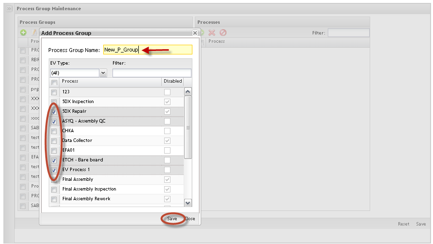
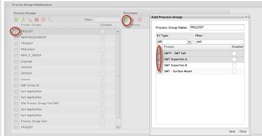
1) ToAdd Process Groups, click on Add icon, fill in the Process Group Name field and select the processes to be added into the process group.
Note: Every time that a new process group is created, the user must associate at least one process to it.
Selecting a process group, the user can see all associated processes.
The selected Process Group will be displayed highlighted in yellow. Selecting the process group, the user can see all associated processes.
Click on OK button to save the changes.
Editing Process Group Name
Figure 20: Edit Process Groups
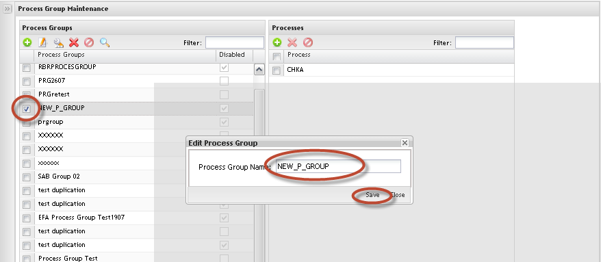
1. To Edit Process Groups Name, select the process group and click on Edit icon.
Just the Process Group Name can be updated. Update the Process Group Name and click on OK to commit the change. To cancel, click on Cancel button.
Editing Process Group Status
Figure 21: Change Process Group
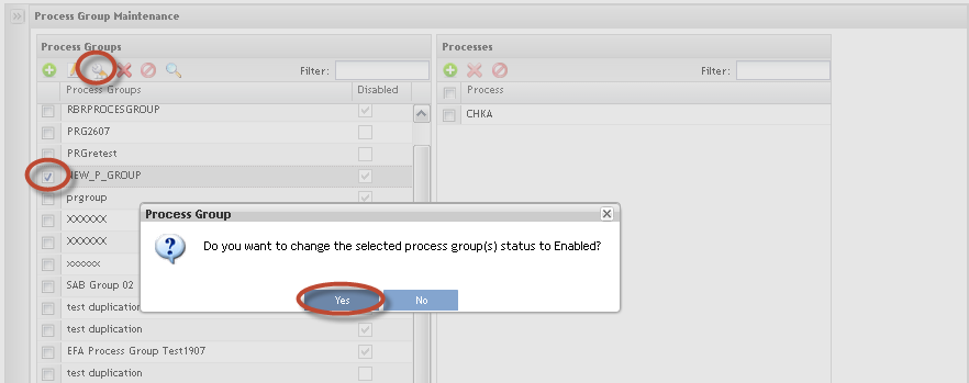
1. To Change Process Group status, from list, select the item and click on Edit Status icon.
Note: The updated Process Group is displayed in red:
2. Click onYes button to commit the change.
Removing Process Group
Figure 22: Remove Process Group
1. To Remove Process Group from list, select the process group and click on Remove icon.
Note: It is not possible to remove process groups if there are associated certificates. In this case, it is possible to only update the processes.
Undo Delete Process Group
Figure 23: Undo Delete Process
1. To undo delete a process group, click onUndo Delete icon.
The selected process group color will be changed and continue displaying in the list.
To commit the changes, click on Yes button. To cancel the changes, click onCancel button.
Process Maintenance:
Searching Process
Figure 24: Filter Processes
1. To Filter Processes already associated with a Process Group, enter the process name (at least 3 chars) in the Filter field. The process displays with the respective associated process group.
Adding Process
Figure 25: Add Process
1. To Add Process, select the Process Group and click on Add Process icon.
The available processes are displayed. Select the process and click on Save button.
The selected process (es) will be displayed in the Processes list highlighted in yellow.
This action could be affecting existing Certificates and the user is able to update it.
Note: A Process can only belong to a single Process Group.
Removing Process
Figure 26: Remove Process
1. To Remove Process, select the Process Group, select the process to be removed and click on Remove Process icon.
If the update on the process group affects existing certificates, the user is alerted and has the possibility to change the certificate before committing the change.
Certificate Maintenance
The next step to configuring Employee Validation is to create the Certificates. Toaccess theCertificates, click on Certificate Maintenance.
The main certificate maintenance page displays:
Certificate List
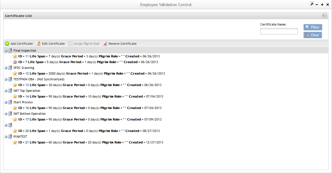
Figure 27: Certificate List
Note that in the Certificate list, it is possible to see some unsynchronized certificates, which means that it has at least one process group that is out of date. In the next steps, the user will be able to turn non synchronized certificates into synchronized certificates.
Adding Certificates
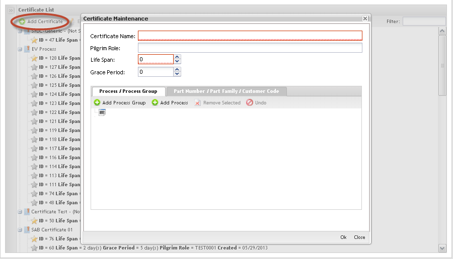
1. ToAdd Certificates and associate processes and process groups or Part/Family to Certificates, click on Add Certificate in the Tasks area.
Figure 28: Add Certificate
The Certificate Maintenance screen displays:
Follow the steps below to add a certificate:
1. Fill in the fields:
Certificate Name: The name of the new certificate;
Pilgrim Role: this field is used to associate the Certificate to a Pilgrim role. It was created to maintain a list of the ’Roles’ in Pilgrim that require training for EV purposes, linked to the EV certificate associated with that role.
Life Span: # of days the certificate is valid;
Grace Period: # of days allowed after expiration (can not be grater than 30);
2. Click on Ok to confirm. The new certificate must display in the Certificate list.
3. Click on the Add Process / Process Group button to define the process (es) and/or groups that are associated to the certificate.
Adding Process/Process Group to the certificate:
Figure 29: Certificate X Process/Process Group
The Certificate X Process / Process Group page displays:
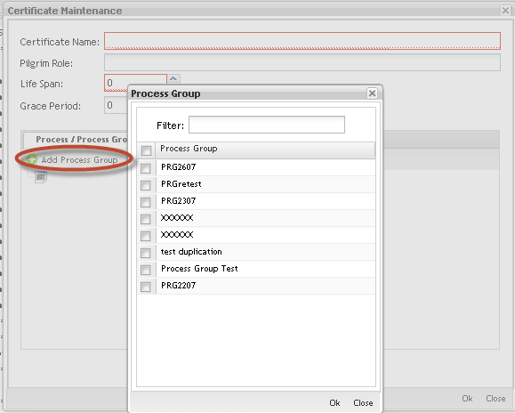
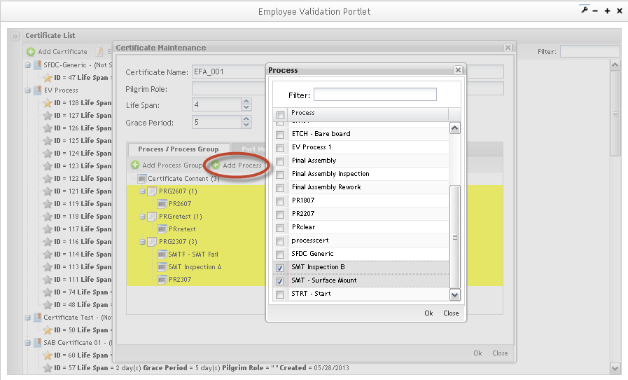
Select the Process Groups check box to add process groups available in the list. Do the same steps to Processes and click on the Add button.
The inserted process/process group is displayed in the Process/Process Group tab.
NOTE: You cannot create a certificate without having at least one process or group assigned.
Figure 30: Certificate Maintenance Process/Process Group Tab
To add Process to the process groups, click on Add Process. The added processes/process groups are displaying highlighted.
a)Creating generic certificates.
If multi-pass device numbers are used in SFDC, then it is recommended to create a generic certificate and assign some process to it. The process does not have to exist in any route. An example would be SFDC Training for the process. The process is not used for any locations or in any route. The process is controlled by Employee Validation and a generic certificate is created for this process.
All employee numbers are associated to this certificate/process. The reason for this is to allow any employee to log into a device number that has one or more EV controlled processes. Without a generic certificate/process, employees would not be able to log into the device number to perform the non-EV controlled processes that are assigned to the multi-pass device number. Employee validation insures that serial numbers that are at a controlled process can only be scanned by employees that have the necessary certification for the controlled process. Without the generic certificate/process, non certified employees will not be able to log into multi-pass device numbers.
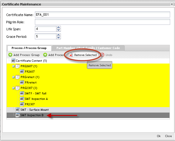
b) To Remove 'CERTIFICATE 'Process/Process Group:
Figure 31: Remove Process Group
Click the process/process group to select it and click on Remove Selected button. The removed process/process group displays in dark gray in the list. To Undo Delete 'CERTIFICATE 'Process/Process Group, select it from list and click on Undo button.
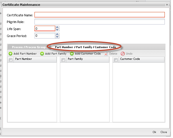
c)Adding Part Number/Part Family/Customer Code to the certificates:
Figure 32: Part Number/Part Family/Customer Code Tab
In addition, users can add Part Numbers/Family and Customer Codes to the Certificate. The rules to add, remove and undo remove are the same described for Process and Process Group.
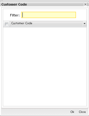
Figure 33: Customer Code
To add customer code, select the item (s) in the list and click on OK.
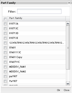
Figure 34: Part Family
To add part numbers/family, select the item (s) in the list and click on OK.
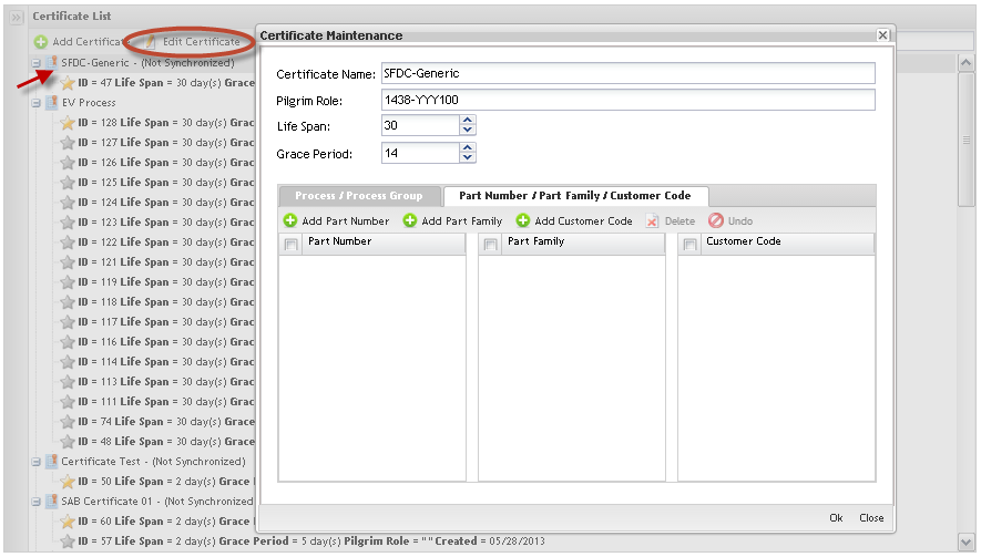
Editing Certificates
1. To Edit Certificates, select the certificate in the Certificate List and follow the same instructions to Add Certificates: update the mandatory fields and click on OK to commit the change.
Figure 35: Certificate Maintenance
NOTE: Every time the user adds a new Process on the Certificate, the application creates a new instance of that Certificate. All classes created before the Certificate changes will be linked to the old Certificate instance.
See the example:
1- Create Certificate CERT with process "A" and "B";
2- Create a Class for CERT with employee Y and Z;
3- Edit CERT and add the new Process "C";
On this example the employees Thomas and Keith will be trained only on the processes "A" and "B". If the certificate is changed, they need to be trained on "C", therefore another class will need to be created for the same CERT.
Figure 36: Certificate Instances
GOLD STAR represents the last update;
SILVER STARS are the old instances that are associated to the classes already created.
Removing Certificates
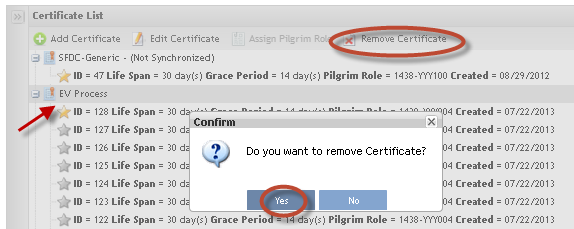
To Remove Certificates from the list, follow the steps below:
1. Select the certificate to be removed;
2. Click on Remove Certificate button. A popup message displays to confirm the certificate removal.
3. Click onYes to confirm or click on No to cancel the removal.
Figure 37: Remove Certificate from List
NOTE: Certificates already associated with classes can not be removed.
Class Maintenance
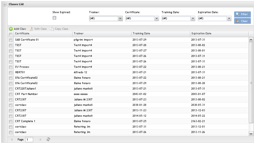
Toaccess theClass Maintenance, click on Class Maintenance option. The Class Maintenance main page is displayed:
Figure 38: Class Maintenance
The user is able to add, copy or edit classes and perform searches from the main class page.
Adding Classes
Figure 39: Add Class
1. Click on Add Class in the Menu bar.
The Class Maintenance page displays:
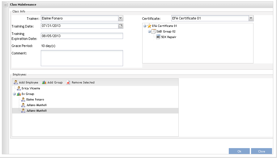
Figure 40: Class Maintenance
1. Select the trainer, the certificate and the date for training from the drop down list. Selecting the certificate, the Grace Period and Training Expiration Date will be automatically filled.
2. Go to Employees maintenance and add the employees who have taken the class, by clicking on the Add Employee button.
NOTE: The class must have at least one associated certificate.
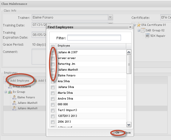
Figure 41: Add Employees
1. Add the Employees clicking on Add Employee.
The Find Employees popup displays to find Employees.
2. Select the Employee (s) and click on OK to commit the inclusion.
To add employee groups:
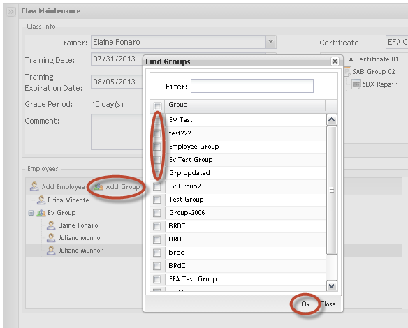
Figure 42: Add Employees Groups
1. Click on Add Group.
The Find Groups popup displays to find Groups.
2. Select the Group (s) and click on OK to commit the inclusion.
Both, groups or employees are displayed in the Employees list.
NOTE: The add Employees by group is a way to make adding employees fast and EV does not store group information, i.e. if the selected group has a new employee added in the future, he/she won’t be added to the class.
Editing Classes
To Edit Classes, select the class to be edited and click on Edit icon. Follow the same steps performed to add classes. Click on Ok button to commit the changes.
