Test Integration
Contents
- 1 Introduction
- 2 Home
- 3 Administration
- 4 Operation
- 4.1 Parser
- 4.2 Dynamic Configuration
- 4.3 Station Group
- 4.3.1 Search station
- 4.3.2 List station group
- 4.3.3 Enable/Disable all stations on group
- 4.3.4 Add new station group
- 4.3.5 Edit a station group
- 4.3.6 List defect mapping groups from a station group
- 4.3.7 Add a defect mapping group to a station group
- 4.3.8 Bulkload defect mapping items to a defect mapping group
- 4.4 Station
- 4.5 AutoSFDC
- 5 Operation
- 6 Monitoring
- 7 About
- 8 Revision Log
Title page
Introduction
Measurement is a flexible, extensible, and high-performance software solution designed to be an integration platform between test equipment (AOI, AXI, 5DX, FP, ICT, FCT, System Test, Burn-In, etc.) and SFDC/MDS. Measurement provides a common gateway for automating simple and complex task chains. It also provides a centralized repository for test parametric data collection and reporting.
Measurement allows engineering to design and build powerful, quick, and error-free mechanisms that automatically perform checks against data available in current or previous test outputs in any MES application. It also automates typical tasks performed by operators scanning on SFDC (subject to data and conditions availability).
The basic out-of-the-shelf solution provides AutoLog mechanisms (to PASS/FAIL UUT - Unit Under Test), mapping test steps to symptom codes (allowing Pareto of symptoms when apply), grouping similar faults (based on symptom mappings) as well as parametric data collecting via DHR (Device History Report). This feature also provides tabular "measures vs. specs" reports that can be easily imported into Minitab for histogram, dispersion, control charts, and normal distribution-curve creation giving engineering statistical reporting over volumetric test data.
Home
Login/Logout
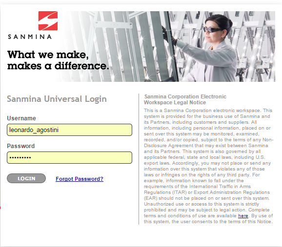
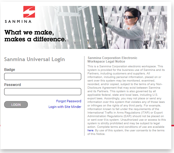
If the Measurement application is accessed with a default instance URL, siteminder credentials will need to be validated.
Figure 1: Sanmina Universal Login
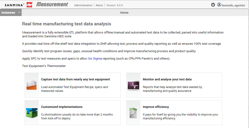
Once logged into Measurement, the user can select the specific instance to operate.
Figure 2: Measurement Home
To logout of the application or switch users, select the Logout icon located at the top right of the screen next to the username. (This button is present in all modules of this application.)
Figure 3: Logout Icon
Once the Logout icon has been selected, the user will be redirected to the Sanmina page.
Instance Selection
The Measurement configuration web application is instance based. All parsers, stations, and any Measurement automated line production related information is stored into a Measurement database. Each instance is set to view one Measurement database. This produces one instance per Measurement installation.
Generally, Measurement is configured to have one installation per site/plant. However, it is not uncommon to have a separate instance at the same site when there are medical operations.
To view available instances in the Measurement application, select the "Instances" dropdown menu.
Figure 4: Instances Menu Location
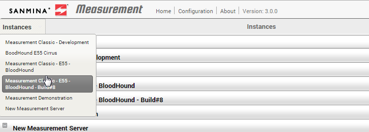
A list of instances will display. Any instance can be selected in order to update the information.
Figure 5: Instances Drop-Down Menu
The instance set will appear as the screen’s title to display the current instance to the user.
Figure 6: Selected Instance
Administration
Users
There is an access control module within Measurement. Currently, the following user profiles are available:
- Global Administrator: A user with access to all instances with the ability to manage user permissions.
- Instance Administrator: A user with the ability to manage instance-related configurations, such as AutoSFDC and Instance Configuration Groups.
- User: A user with the ability to manage all configurations contained in accessible instances.
- Operator: A user with the ability to use checklist and activity monitor modules in accessible instances.
To access the User management module, select Users from the Configuration dropdown list.
Figure 7: User Configuration
List user accounts
When entering the Measurement User Management module, Measurement loads all users from all instances. The following information is shown:
- Username: The active directory username for the Sanmina account.
- Badge: The user’s badge number used in the Checklist module to send to AutoSFDC for test registration.
- Instances: The Instances list to which the user has access.
- Permission: The role to which the user is assigned.
- Enabled: Applies when the user has access to Measurement.
Search for a user
The User module also offers a search mechanism. To use this function, click on the title bar to expand the search area.
Figure 8: Search User
Filter fields include Username, Permission, and Enabled. Users can use more than one filter. Click Search to filter the result according to the criteria entered. To reset the filtered results, clear the filters and select Search.
Figure 9: Filtered Result
Enable / Disable an user account
To remove user access to Measurement accounts can be disabled. Removal operations can be reversed and the user retains his or her privileges.
To enable a user account, click on the Enabled icon for a given account in the User list.
Figure 10: Disabled User Account Icon
The user has enabled status (in green). To disable his account, simply click again on the same button.
Figure 11: Enabled User Account Icon
Add a user account
Note: User must be a Global Administrator to perform this operation.
To add a new user, click on the New icon at the top of User list.
Figure 12: Add New User Icon
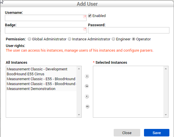
Measurement loads the users form screen, which contains the following fields:
- Username: The active directory username from the Sanmina account.
- Badge: The badge number of the respective user; this is used in the Checklist module to send to AutoSFDC when registering a test.
- Password: The password to log on to the Checklist module; this is a different password from Active Directory.
- Permission: The role to which the user is assigned.
- Enabled: Applies when user has access to the Measurement application.
Figure 13: Add User Window
The instances that can be assigned to users are listed in the All Instances box. To grant a user access to an instance, select an instance from the All Instances box and move the instance to the Selected Instances box by selecting the arrow button pointing toward the Select Instances box. When finished, click Save.
Note: Users cannot give user permissions higher than that of their own.
Once Save has been selected, the system validates the user as a Sanmina employee and stores the user in the Measurement database. Exit the Users form at which point the user list is reloaded, and should now include the new user.
Edit a user account
In the event there is a need to change user permissions or roles, the user account should be edited. This requires that the role of Global or Instance Administrator. To edit a user account, click the respective user’s Edit (pencil) icon.
Figure 14: Edit User Account Icon
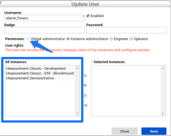
As was noted earlier, an Instance Administrator cannot change user permissions to Global Administrator, as the latter permissions are higher than those of the former. The only instances to which users have access are available in the Instances list.
Figure 15: Update (Edit) User Account Window
After selecting Save, Measurement validates the information and stores the data in the Measurement database. The window will close, and the User list will reload, showing the new user.
Remove user account
To remove a user account from Measurement, simply click Delete. Note: Users must have Global Administrator privileges to perform this action.
Figure 16: Remove User Account Icon
When selecting Delete, a prompt pops up requesting confirmation of the action. When confirmed, the user is removed from the database and the User list is loaded, which no longer lists the removed user.
Figure 17: Delete User Account Confirmation Message
Instances
An instance is used to handle a group of jobs (Parsers) that are responsible for importing test results from many types of channels, process them, communicate to SFDC accordingly, etc.
Note: Only Global Administrator users can manage instances.
As a Measurement installation, an instance is composed of a Measurement Engine Service, a Measurement Database, and Parsers. An instance can have multiple programs running in the same box (same Windows server) reaching different Measurement databases as well as different MESR databases.
To access the Instance module, navigate to the Administration page at the top menu and click on Instance in the Configuration menu.
Figure 18: Configuration Menu - Instance
List instances
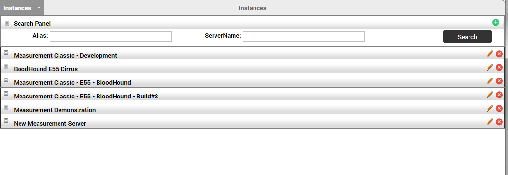
When entering the Instance module, Measurement loads all instances and lists them on the screen. To see instance information, select the expand icon (denoted by the "+" symbol) located to the left of the respective instance name.
Figure 19: Expanded Instance Information
Search for an instance
The Instance module also offers the ability to filter and search instance items. To perform these functions, expand the search panel at the top of the Instance list, complete the appropriate filter fields, and click Search. Currently Measurement provides filtering instances by alias and server name.
Figure 20: Search Instances Panel
To reset the filter in the Instances list, clear the information previously entered into the fields. Then, select Search.
Create new instance
When a new instance in a site requires installation, select New from the Instance module at the top right of the Instances list.
Figure 21: Create New Instance Icon
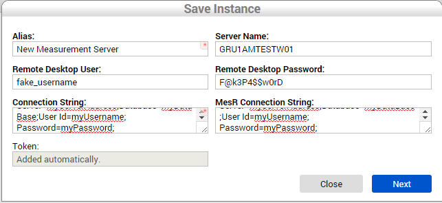
Measurement loads the Instances form screen. At a minimum, the mandatory fields must be completed (i.e., those denoted by a red star in the top right corner of the field):
- Alias: The organizational name given to identify an instance on the tool.
- Server Name: The server name configured on the OS from the Measurement server with the given instance.
- Remote Desktop User: The username on the server used to remote connect on the desktop. This is for future reference, not used by Measurement.
- Remote Desktop Password: The user password to allow a remote connection to the desktop. This is for future reference, not used by Measurement.
- Connection String: The Measurement database connection string used to run the Measurement configuration modules.
- MesR Connection String: The MESR (MDS Replication) database connection string used to retrieve MDS data, such as process, defect codes, and other information.
- Token: The automatically-generated unique identifier.
Figure 22: Save (Create) New Instance Window
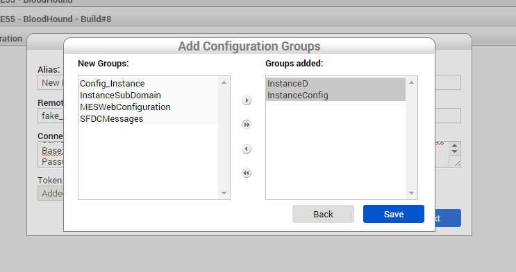
Once Next is selected, the Add Configuration Groups window appears containing a list of configuration groups to assign to this Instance. The available groups are in the left New Groups box and are titled New Groups. To assign to this instance, select one or more items by holding the Ctrl key while clicking one or more group names. Then, select the arrow pointing toward the Groups Added box. This action transfers the selected New Groups to the Groups Added box. When finished, select Save. The instance information is stored and the Instances list is refreshed.
Figure 23: Add Configuration Groups Window
Edit an instance
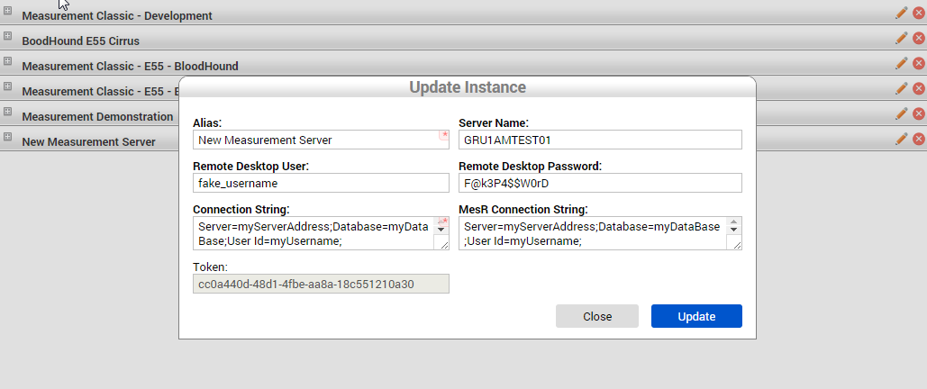
To change any value in an instance, click the Edit (i.e., pencil) icon at the right side of the respective instance in the list. This action loads the instance form screen that allows its fields to be changed.
Figure 24: Edit Instance
Figure 25: Update (Edit) Instance Window
After editing the values, select Update. Measurement validates the changed values, and in the validated condition stores the data and refreshes the instances list after closing the Instances form screen.
Remove an instance
This feature is generally used in the case of Measurement installation and is no longer necessary in a plant or a merger between installations.
An instance removal does not erase any test result data from the Measurement database. Removing an instance only removes web access to the database. In case it is necessary to erase measurement or parametric data, users are advised to contact the Measurement support team.
To remove an instance from the list, click Delete to the left of the respective instance item.
Figure 26: Delete Instance Icon
A confirmation box is displayed, and once the action is confirmed, the instance items are removed from the list and from the Measurement database. The List is refreshed and no longer shows the items that were removed.
Associate a configuration group to an instance
Instances can also have additional configurations. These configurations are generally used by the Measurement team to implement instance-level customization of Measurement installation that is common to all parsers or integration with other applications.
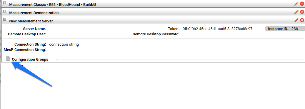
To see the configuration groups associated to an instance, after expanding the instance information box, click on the link Configuration groups at the bottom of the instance information panel.
Figure 27: Associated Configuration Groups
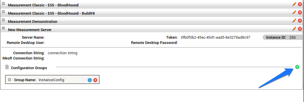
Once Configuration Groups is selected, Measurement shows the groups associated to this instance item.
To add an existing configuration group to this instance, click the New icon at the right side of the Configuration Groups section.
Figure 28: Add Existing Configuration Group Icon
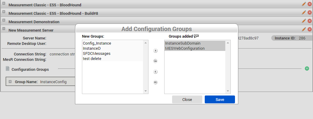
The same screen from the Add an Instance step will display with the existing groups in the left box, and the ones to intended to be associated in the right box. Move items by selecting them and then clicking the arrows pointing to the destination box.
Figure 29: Add Configuration Groups Window
After moving the desired groups to the Groups Added box, click Save. The Added Groups will now show in the Configuration Groups section from the instance item.
Figure 30: Displayed Newly Added Configuration Groups
Configuration Groups
Measurement provides a module to customize the way parsers work. During the analysis phase from a Measurement project, there are a few details that need to be setup or configured, and they must be flexible enough to be changed by the engineering team or the plant support team without requiring a code change or stopping the line.
Configuration must be implemented on the parser, and Measurement provides a cockpit for the user or operator to change these values from a parser.
On this administration area, configuration groups can be created in which parsers and instances may be used. Also, the same configuration group is available for all parsers with this instance, which means a group can be created once and be used for all desired parsers. To perform this action, associate the group to a parser and input their values.
To access the configuration group module, from the Administration taskbar, click Configuration and then select Configuration Groups.
Figure 31: Configuration – Configuration Groups
Figure 32: Configuration Groups – Select Instance or Parser
Upon entering the Configuration Groups module, select to manage Instance configuration groups or parser configuration groups. If Instance is selected, Measurement will load all configuration groups from this instance and show them in a list. If Parser is selected, Measurement will prompt the user to select the instance from which to manage configuration groups. Once the instance is selected, click on Show. Measurement will load the parser’s configuration groups per the selected instance.
Figure 33: Parser Option Dropdown
Create new configuration group
To create a new configuration group, click on the Add button at the top of Configuration Groups list. Measurement opens the last list line for editing.
Figure 34: New Configuration Group Icon
After entering the Group Name and description (optional), select Save. Measurement will validate if the name is unique for this instance and reload the list showing the new entry.
Figure 35: New Configuration Group Item
List configuration items from a group
To list the items from a configuration group, click on the List Items (paper) icon on the Actions column from the configuration group item row.
Figure 36: Configuration Group - List Items Icon
Measurement loads the configuration items with the items displayed and opened for editing.
Figure 37: Configuration Groups Item Forms
Add items to a configuration group
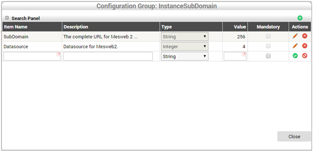
In the Configuration item list, click on the New button at the top right from the configuration items list form. Measurement opens the last line for editing. After completing the mandatory fields, select Save.
Measurement opens another line to include a new configuration item:
- Item Name: The name of the configuration item, this will also be used on the parser to identify the configuration item.
- Description: The text describing the purpose and how to use (fill) the item.
- Type: The data type from this item.
- Value: The required max length value.
- Mandatory: The item to have a mandatory value when set to true.
- Static: The marked value indicates the group has just one value from the respective configuration item.
Figure 38: Adding Items to a Configuration Group
When finished, click Close at the bottom of the page.
Edit a configuration item
To edit a configuration item, click the Edit (i.e., pencil) icon in the Actions column for the respective item to be edited. The fields become available for changing. Once the changes have been made, click on the respective Save button within the Actions columns. Measurement will validate the input data and after validation will store the data and refresh the Configuration item list.
Figure 39: Editing a Configuration Item
Delete a configuration item
To delete a configuration item, click on the respective Delete (i.e., red X) icon in the Actions column adjacent to the item to be deleted.
A prompt is displayed to confirm the deletion. Once confirmed, the item is removed from the database.
Figure 40: Deleting a Configuration Item
Edit a configuration group
To edit a configuration group, click on the Edit Group (pencil) icon in the Actions column in front of the configuration group to be changed. Measurement allows the fields to be edited and their values to be changed. Next, click on Save in the Actions columns. Measurement will validate the input data, store the data upon validation, and refresh the configuration group’s list.
Figure 41: Editing a Configuration Group
Remove a configuration group
To delete a configuration group, click on the Delete (i.e., red X) icon in the Actions column corresponding to the configuration group item to be changed.
A confirmation message will appear. Once the action is confirmed, the item is removed from the database and list.
Figure 42: Removing a Configuration Group
Operation
Parser
List parsers
Upon entering the application users will see the parser list screen where all Measurement applications that are installed or running are displayed.
Every line of the parser list represents a parser instance. There can be multiple instances from the same parser that point the source test data to different paths, in the event there is a need to segregate lines or increase file processing performance by having two or more parsers running in parallel.
Figure 43: Parsers
Search parser
To find a specific parser, use the search function at the top of the parser list. Expanding the Search panel reveals the filters field that can be used for performing searches.
Figure 44: Search Parsers
A search can be performed by Parser Name, Customer, Import Type, and select to filter only Enabled parsers. When information has been entered into one or more filters, select Search.
Create new parser
1. In order to create a new parser, click on the green plus icon at the top right of the screen. This will open the parser edit screen.
Figure 45: Create New Parsers
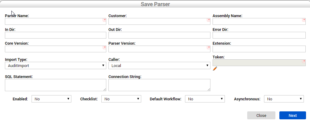
2. Fill out all mandatory fields and select Next:
- Parser Name: Or parser alias; this will helps identify the given parser instance on the parser screen.
- Customer: The general designation that identifies from which customer the automated line is processing their products.
- Assembly Name: The full qualified name from the parser file, including its extension.
- In Dir: The full qualified path the parser will use to collect test result files.
- Out Dir: The full qualified path the parser uses to store the processed test result files.
- Error Dir: The full qualified path the parser will use to store the test result files that failed while being processed.
- Core Version: The four-digit version from Measurement application the parser was deployed to run.
- Parser Version: The four-digit version number from the parser assembly file.
- Extension: The file extension the parser is set to use in association to the In Dir to collect the files. (e.g., *.txt, the parser will collect from In Dir only the files with .txt extension).
- Import Type: Informative data to identify the import mechanism the parser uses.
- Caller: Sets how the parser will run.
- Local: Sets the parser to be run from Measurement Core.
- Remote: Sets the parser to be loaded from another parser.
- Token: A unique identifier string associated to a parser instance.
- SQL Statement: The field used to store the SQL query for loading the test result data. Applies to parsers which have the import type set as Database.
- Connection String: The field used to store the connection string which the parser uses to connect to the source files database. Applies to parsers which have the import type set as Database.
- Enabled: The option determines whether the parser is set to run or stop.
- Checklist: This option sets the parser to run in Checklist mode. This setting grants parser stations the ability to generate checklist links and perform manual tests.
- Default Workflow: Technical option set by the developer to identify the parser to run in a default workflow (i.e., import data, parse to measurement data, send unit information to SFDC, store parametric data, and release the file to out folder).
- Asynchronous: Determines whether the parser will process multiple serial numbers in parallel on SFDC.
Figure 46: Parsers – Save New Parser Form
Note: The mandatory fields are indicated by a red star located in the top right of the applicable fields.
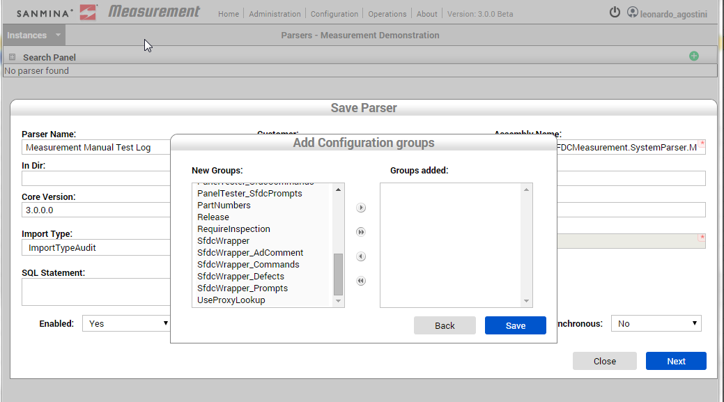
3. When Next is selected, the application opens a box to add Configuration groups. These groups are existing parser setup configurations. This step is optional, in that the user can associate or create new sets later. At this point, selecting Save will save the parser and pull up the parser list screen.
Figure 47: Parsers – Add Configuration Groups
4. Parser list screen with the new parser.
Figure 48: Parsers – New Parser
Enabled / Disable a parser
Measurement Core application is configured to run the parser every set number of seconds. Hence, all enabled parsers will run after a designated amount of time has passed.
There are certain scenarios when it is not preferable for a parser to process test result files. These scenarios include when the line is under maintenance, stations are being adjusted, or the SFDC is being updated. For such events, there is a quick way to enable or disable a specific parser:
Figure 49: Enable or Disable a Parser
The first circled button is the Enable/Disable parser function. This button becomes red or green depending on the parser’s current status. In the illustrated case, notice that the parser is currently enabled since the parser title is green. Hovering the cursor over the button generates a pop-up message that notifies what action that will occur if the icon is selected.
Figure 50: Parsers – Close-up of Enable/Disable Icon
Note from the above and below illustrations how the color of the parser icon changes when selected, thus indicating the parser’s status: Green indicates that the parser is enabled whereas red indicates that the parser is disabled.
Figure 51: Disabled Parser
Edit a parser
Managing test stations, defect mapping, dynamic configuration, or even parser status does not need be performed from Edit mode; however, if there is a need to change their characteristics or source paths, it will be necessary to edit the parser. Note that when we edit an enabled parser, the changes will only take place when we confirm the changes by select Save. Otherwise the parser continues running with its current configuration set.
To edit a parser, click the Edit (i.e., pencil) icon.
Figure 52: Editing a Parser
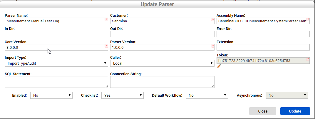
Measurement opens an Update Parser screen similar to the Add New Parser screen. From here users can change all fields. Click Update to confirm the changes.
Figure 53: Update Parser Form
After selecting Update, Measurement loads the Parser list screen with the updated parser information displayed.
Delete a parser
Generally, a parser is used for a specific line, product, or customer. When a customer moves their production to a different company or the product line changes and the parser is no longer necessary, this parser can be deleted to prevent an application with has nothing to process from running. When a parser is removed, all data that this parser has created, such as parametric data and test result activities, are not deleted; the station’s devices will be available for use at other stations.
Figure 54: Deleting a Parser
There is also a Restore function that allows a previous parser to run again. This action can only be performed by Global Administrator users.
Clone a parser
Cloning a parser allows for creating a new instance of a parser based on the configurations of an existing one. All configuration items with their current values are copied, which includes station groups and defect mappings.
When cloning a parser, all copied stations are set with a device value of -1 to ensure that there is no conflict between SFDC devices.
When the Clone icon is selected, a new instance with same parser name will appear that includes the additional text "- Copy".
Also, the In Dir, Out Dir, and Error Dir properties receive a "_new" suffix in order to avoid source path conflict between parsers.
Figure 55: Cloned Parser Success Message
Restore a parser
The Restore a parser function allows the user to restore a deleted parser. A parser is not entirely deleted when the user performs a parser removal operation. All data for the removed parser continues to be stored in the CPR database; however, this data is not used with other parsers.
The Restore icon is only available for removed parsers, and only Global Administrator users are able to perform this function.
Figure 56: Restore Icon
After selecting the Restore button, the parser name no longer displays the strikethrough font, and can be enabled again.
Figure 57: Restored Parser
Dynamic Configuration
A parser has a well-defined workflow structure based on inbound processing, optionally integrated to SFDC and outbound information. Due to customer-requirement based customizations, line differences, and technical integration issues, a place is needed to store additional configuration items and values; hence, the dynamic configuration module. This name is used to reflect that a set of configuration items can be created for each parser or instance with different types and values. Also the same configuration set can be assigned to different parsers, and each parser can have its own values.
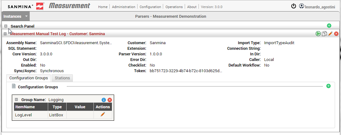
To see the assigned configuration sets for the parser, click on the Configuration Groups tab at the bottom of parser’s information.
Figure 58: Parsers – Assigned Configuration Groups
Associate an existing group
To associate an existing configuration group to a parser, click the green plus icon to the right, inside the Configuration Group tab.
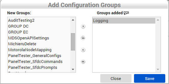
Measurement loads the existing configuration group list screen into two boxes. The left box, New Groups, contains a list of existing groups, and the right box, Groups Added, contains a list of associated groups to the respective parser.
To associate a configuration group to a given parser, first select a group and click an entry from the list. (Multiple groups may be selected by holding down the Ctrl key while selecting each entry.) Then, select the arrow icon pointing to the right (or click on the two arrow icon to move all items). Next, click Save.
Figure 59: Parsers – Add Configuration Groups
To undo the selection of added groups, select the group in the right box and click the arrow icon pointing to the left. Select Save to complete the action.
Figure 60: Parsers – Saved Configuration Group
Add/Edit values to an existing group
After associating a configuration group, the parser adds values to its items.
When expanding the configuration group, it shows all items from the respective group, their data types, and the assigned value (it is empty when has no value).
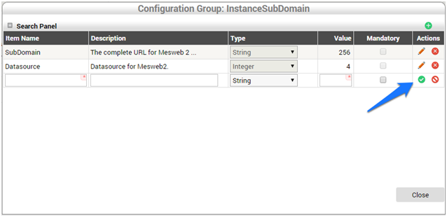
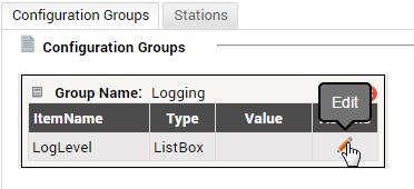
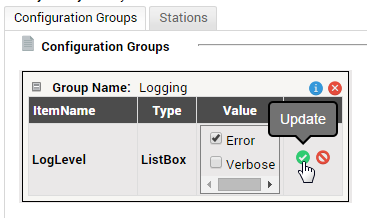
To add a value, click the Edit (i.e., pencil) icon to configure the respective item. Then, input the value and hit the green icon to save it.
Figure 61: Parsers – Add Configuration Group Values
Figure 62: Parsers – Configuration Groups Update Icon
Remove associated configuration group
If a configuration group is ever included by mistake or the configuration is no longer need due to a parser upgrade, the configuration group association to this parser may be removed.
Note: This operation only removes the association between this parser and the configuration group. The configuration group will continue to be available for other parsers.
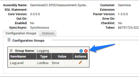
To remove an associated configuration group, click the red icon at the top right on the configuration group box.
Figure 63: Parsers – Remove Configuration Group Icon
Station Group
Station groups are a way to group the Measurement test stations items that have the same AutoSFDC. Also, the stations share the same defect mapping groups associated to their group.
There are a few rules for maintaining stations between groups in Measurement in order to avoid SFDC device conflicts:
- Both station groups cannot have the same name associated to the same parser.
- A station group can be associated to only one AutoSFDC.
- A station can have just one device, and this device should be unique between all stations from different station groups associated to the same AutoSFDC.
- Multiple stations can be assigned to the same device ID within the same parser when the parser is synchronous.
- A station name should be unique per parser, even being associated to a different station group.
Figure 64: Parsers - Stations
Search station
In order to manage and quickly find a specific station group or station on the list, there is a search mechanism at the top of the station group’s list. After expanding the box, the filters field available for filtering the list can be seen.
Figure 65: Parsers – Station Filter and Search
After filling one or more filters, click on Search. To clear the filtered results, delete the information in the filters and click Search.
List station group
In the Stations tab inside parser information group, there is a list of stations grouped by their Station’s group sections. There are a few operations we can perform on this list that are available on the right side of each station row—namely, Defect Mapping Groups, Station Bulkload, Edit, and Delete stations. Each are described separately.
Figure 66: Parsers – Station Action Icons
Enable/Disable all stations on group
This feature is generally used when there is a need to stop the production line briefly for maintenance or testing. This action stops or enables all stations from a specific group.
In the below image, note the red arrow that points to the stop all stations icon and the blue arrow pointing to the enable all stations button.
Figure 67: Parsers – Stop and Enable All Station Icons
Add new station group
To add a new station group, click on the Add New Station Group in the search panel inside the Stations tab on a given parser.
Figure 68: Parsers – Adding a New Station Group
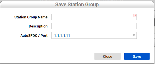
Measurement loads the Save Station Group window in order to fulfil the station group information.
Figure 69: Parsers – Save Station Group Window
Each Station group must have an AutoSFDC attached. This means all stations inside the group will be validated against this AutoSFDC, including the defect mappings (defect codes), devices, and processes.
After clicking on Save, Measurement will validate the input data and save the station group information.
Measurement loads the updated station group list on the parser’s list screen.
Figure 70: Parsers –Displaying Added Station Groups
Edit a station group
Measurement currently offers the ability to change name and description fields from a station group item. The AutoSFDC information is locked due to a security concern regarding SFDC communication using unknown defect codes or device conflict between parsers having stations with same devices on the same AutoSFDC items.
To edit name and description from a station group, click the Edit (i.e., pencil) icon adjacent to the respective station group name.
Figure 71: Parsers – Edition a Station Group Icon
Measurement opens the edit station group screen, which is similar to the add station group screen. Change the name or description and click Save.
Measurement reloads the station group list, which should now include the updated list.
Figure 72: Parsers – Updated Station Group List
List defect mapping groups from a station group
Measurement is able to use defect code mapping to send specific SFDC defect codes based on tester defect code or by using a single generic defect code if the customer prefers.
To see all defect mapping groups from a station group, click on the Show Defect Mappings icon in the Action column in front of each station group.
Figure 73: Parsers – Show Defect Mappings Icon
Add a defect mapping group to a station group
On the Defect Mapping group list screen, click the New button at the top of the Defect Mapping list screen.
Figure 74: Parsers – Add Defect Mapping to Station Group Icon
Measurement loads the Defect Mapping list screen with the form opened on the last line of the list. After typing the Defect Mapping Group Name and (optionally) the Description, select Insert. The new group is saved.
Figure 75: Parsers – Saved Defect Mapping Item
After adding the measurement group, input the defect mapping items. Expand the defect mapping group, and click New at the Defect Mapping group item.
Figure 76: Parsers – Add Defect Mapping Items Icon
Measurement loads the defect mapping item screen. Type the tester defect code and select an existing SFDC defect code on the right side. Click Insert.
Figure 77: Parsers – Add Defect Code Insert Icons
Bulkload defect mapping items to a defect mapping group
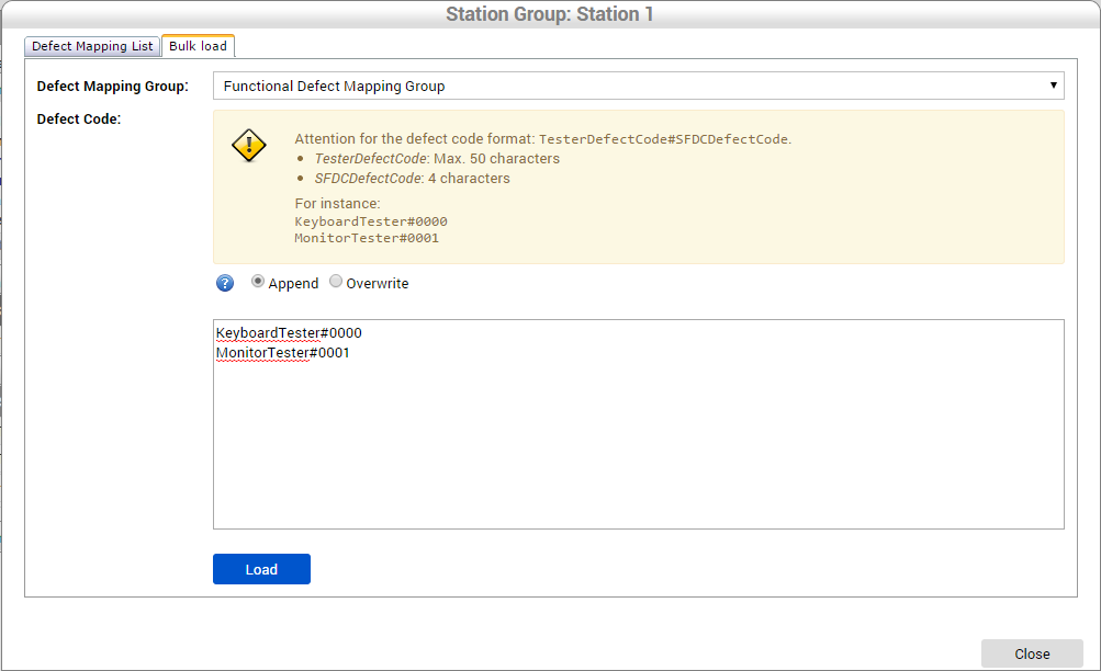
If there are multiple defect items to be added, use the Bulk Load feature to insert all items at once. From the Defect Mappings screen, select the Bulk load tab at the top of the screen. Choose an existing defect mapping group (an empty defect mapping group is acceptable) and select the bulk load options of either Append or Overwrite. (Append mode means that Measurement will keep the existing defect mapping list and include the new item to the list.) The Overwrite option will remove all existing items and add the ones on the list.
The mapping should be entered in the format of one per line, and separated using the "#" character between the tester defect code and the SFDC defect code.
Figure 78: Parsers – Bulk Load for Adding Defect Mapping
After typing all defect mapping items, select Load. Measurement will validate existing defect mapping items and verify the SFDC codes exists in MDS. If valid, Measurement will save the defect mapping items, which will be displayed with an error.
Figure 79: Parsers – Bulk Load Result
Station
The Station Mapping module is built based on a look-up record concept for linking a test station name to an SFDC device number.
This module allows different test station names from several customers and brands to be connected dynamically to SFDC or MDS Locations and Workstations. Device linking also allows for leveraging the multi-pass data collector feature that permits using a single device with more than one station.
List stations
To list all stations from a station group, expand the station group row.
Figure 80: Parsers – Station Group Expand Icon
Station does not have a search inside the station group box. Measurement permits searching for a station on the parser level, using the Search Panel at the top of the Station Group list. The result set is segregated into the station groups.
Add a station
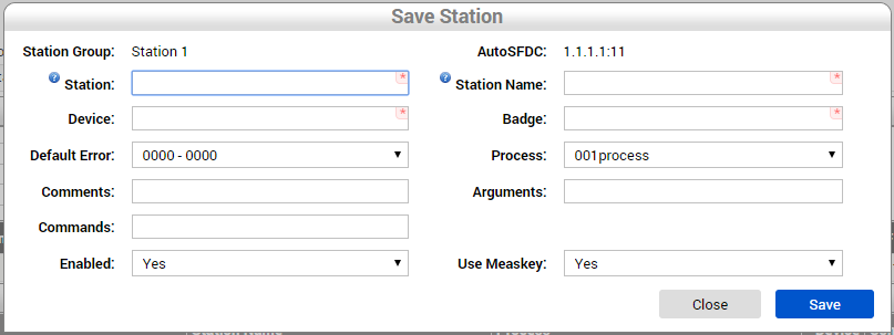
To add a new station inside a station group, click the New button. Measurement will load the Station form.
Figure 81: Parsers – Add a New Station Icon
Figure 82: Parsers – Save Station Group Window
Complete the mandatory fields, and select Save. Measurement will validate the data and add the new station to the group. The station’s list screen should load showing the new station inside:
- Station Group: The name of the group of the station.
- Station: The station ID. Measurement parsers generally use this field to match a station and device mapping from test result data station identification.
- Device: The SFDC device number which Measurement will use to communicate to SFDC when using this Station mapping.
- Default Error: In case there is no defect mapping found for the defect being recorded, Measurement uses this default defect code in SFDC to fail a unit.
- Comments: A generic field to be used on a parser.
- Commands: A generic field to be used on a parser.
- Enabled: The setting that determines whether the station is used while processing test result data.
- AutoSFDC: The SFDC PC used by the parser to send data.
- Station Name: A personal identification, such as an alias, to be used on the given station.
- Badge: The default operator for logging in to SFDC in case the information is not provided on the test result data.
- Process: The MDS process to which this test station belongs. This will be used for recipe creation and Checklist module for receipt identification.
- Arguments: A generic field to be used on parser.
- Use Measkey: The setting that determines whether the parser sends the MEASKEY command to SFDC. When set to Yes, Measurement sends the MEASKEY command to SFDC and links this MDS Activity to Measurement parametric data generated by the test. This setting allows the parametric data to be seen from the test inside the MESWeb Unit History report.
Edit a station
To edit a Station, at the Station list from the station group section, click the Edit (i.e., pencil) icon at the right side of the station row.
Figure 83: Parsers – Edit a Station
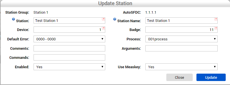
Measurement loads the station edit screen. After changing the values, select Update. Measurement then validates the information and saves the station in case the data is consistent. Measurement loads the Station list showing the updated station data.
Figure 84: Parsers – Update Station Window
Enable/Disable a station
A station can be associated to a parser in an inactive mode, which means this parser will not use station mapping to communicate with SFDC. Enabling and disabling a station is nearly identical to the process of enabling or disabling a parser.
To enable a station, click the green button (play icon) in the Actions column from the respective station row. Otherwise select the red button (box icon) to stop a station.
Figure 85: Parsers – Enable and Disable Station Icons
After clicking on the icon, it changes to the opposite action. For example, if the station is disabled and a user clicks on the Enable button, the station is enabled and the button now becomes the Disable button and vice-versa.
Delete a station
The operation to remove a station can only be performed in case the parser did not generate any activity using this test station.
In case there is a need to free up the device, or use it in another station, disable the station and use the same device in the other test station entry.
To remove a station, click the Delete button (i.e., X icon) and confirm the operation. If this station is unused, it will remove the entry and reload the Station list, and will no longer display the entry that was removed.
Figure 86: Parsers – Delete a Station Icon
AutoSFDC
The AutoSFDC module is responsible for configuring the SFDC/MDS servers to be used by parsers to communicate with SFDC (sending commands based on test result) and mapping MDS Servers to be used in defect mapping modules as well.
AutoSFDC lists are stored at the Instance level, which means the same AutoSFDC item can be used by different station groups in different parsers.
List AutoSFDC items
To list all AutoSFDC items, click on AutoSFDC link at the Configuration menu. Only Instance Administrators can change AutoSFDC information.
Figure 87: Listing AutoSFDC Items
Measurement loads the AutoSFDC list screen.
Figure 88: Loaded AutoSFDC Screen
Add a AutoSFDC
To add a new AutoSFDC item, select the New icon at the top of AutoSFDC list screen.
Figure 89: Add AutoSFDC Icon
Measurement loads a new entry at the bottom of the AutoSFDC list table.
Figure 90: AutoSFDC Table New Entry
Provide all mandatory information and click Insert (green/white OK icon). Measurement will validate and save the AutoSFDC information and reload the AutoSFDC list with the new AutoSFDC item:
- IP Address: The IP Address from the SFDC PC.
- Port: The TCP port connect on the SFDC PC. Default value is 18000.
- Project: Select the MESR project in which Measurement will load Process and Defect Code lists.
- URL: This is used to store the AppServer and retrieve MDS data. In a Cirrus-based MDS, add the MDS Open API REST-based. For the Legacy MDS version, use the AppServer URL.
Edit a AutoSFDC
To change any AutoSFDC value, just click the Edit (i.e., pencil) icon for the respective AutoSFDC item in the Actions column.
Figure 91: Edit AutoSFDC Icon
Measurement opens the AutoSFDC item for editing, making all fields available for change.
Figure 92: Editing AutoSFDC Fields
Change the data. Confirm by clicking Save (green/white OK icon). Measurement validates, stores the data, and reloads the AutoSFDC list with the updated information.
Remove an AutoSFDC
Removing an AutoSFDC item is only possible when there is no Station Group associated with the item.
To remove an AutoSFDC, click on the Remove button (i.e., X red button) located on the respective AutoSFDC item actions’ column at the right side of each AutoSFDC item row.
Figure 93: Remove AutoSFDC Icon
When Remove is selected, a confirmation message appears. Selecting OK validates whether there are any Station Groups using the AutoSFDC and, in negative cases, removes the AutoSFDC from the application.
Search AutoSFDC items
The AutoSFDC screen also has a search mechanism. On the AutoSFDC screen, click on the Search Panel box. Measurement opens the search fields. Type the IP Address, Prefix, or Description; then click Search. More than one field can be used with the search function. Selecting Search loads the list of AutoSFDC items that match the filter parameters. These results are then displayed in the AutoSFDC list.
Figure 94: AutoSFDC Search
To clear a search, erase all fields and again select Search.
Operation
Recipe Maintenance
Measurement usually extracts recipe (sequence, specs, etc.) information from test equipment output and occasionally from a special repository.
In some situations it is necessary to create recipes to manage specific scenarios, such as calculated columns (based on other steps from the same recipe) or to collect offline test equipment measures. This allows for the creation of a test checklist where the operator will be prompted to supply measured results manually.
Create a new recipe
Access the recipe maintenance module in Measurement (http://demo.measurement.sanmina.com), under the Configuration menu item.
Figure 95: Recipe Maintenance
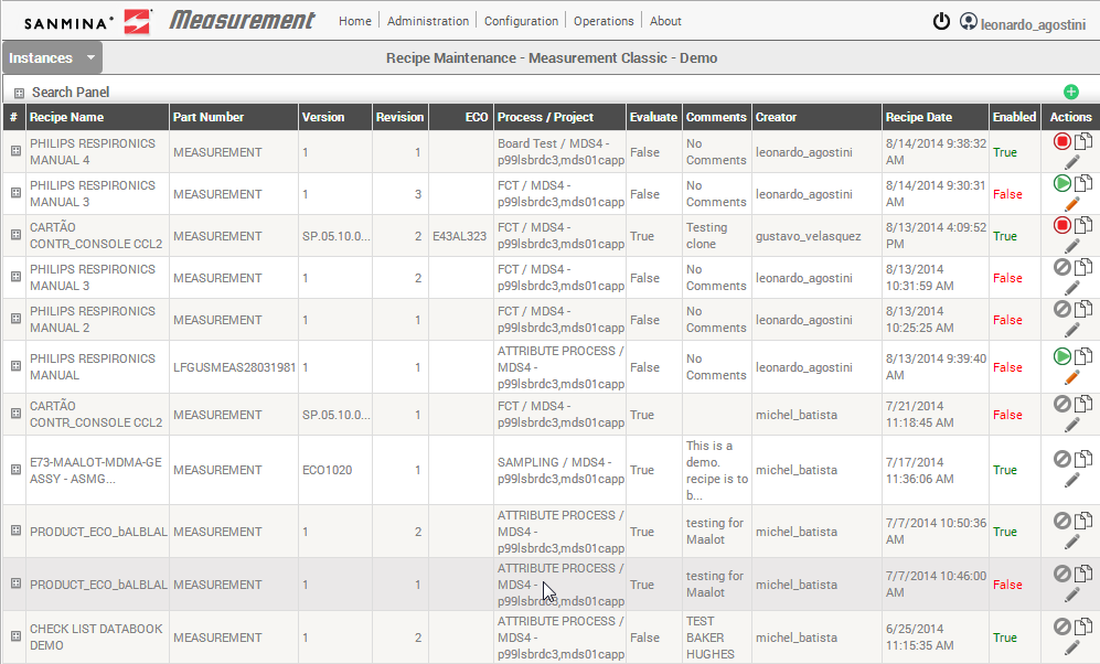
The Recipe Maintenance first screen should load all existing manual recipes with their information and current status. The specifications of multiple versions of the same recipe can be changed, such as parametric measurement groups and items.
The first screen should look similar to the following image:
Figure 96: Recipe Maintenance Screen
To create a new recipe, click the New button at the upper right corner.
Figure 97: New Recipe Icon
Measurement creates a new row at the bottom of the list to add the recipe header information.
Figure 98: New Recipe Header Row
The user must supply all mandatory information such as Recipe Name, Part Number, Version and Process:
- Recipe Name - The identifier name for the given recipe. The name is not unique since there can be different versions of the same recipe.
- Part Number - The recipe is targeted to test. A recipe can only be associated with one Part Number. If there are multiple Part Numbers using the same recipe specification, the recipe can be cloned and the Part Number of the clone changed.
- Version - This is an open field in which is used to manually organize different versions from the same recipe.
- Revision - This field is incremented every time an existing recipe is cloned, and retains Part Number and Process from the original one or creates a brand new recipe using existing PART/PROCESS pair.
- ECO - Engineering Change Order. This informative field associates the recipe to a change order specification.
- Process / Project - Mfg Process in which this recipe will be used. It is also used to filter the list of test stations.
- Evaluate - Check this option if to have Measurement evaluate data input and make decisions on each test step status, based on recipe specs (limits) and comparators while using the recipe. If measured value matches recipe specs and comparator, then a PASSED status occurs, otherwise the status is FAILED. When this option is unmarked, Measurement will only store the measured value (everything will be disregarded and units will always PASS).
- Comments - Informative field.
- Creator - Automatically collected: logged on user creating this recipe.
- Recipe Date - Automatically collected: timestamp of creation.
- Enabled - Recipe activation status. When False, this recipe will not be loaded by Measurement at Manual Test Log module. Only one RECIPE can be ENABLED for a particular PARTNUMBER/PROCESS pair at a given time.
Figure 99: New Recipe Information Entered
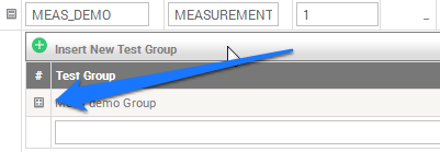
Click on the Expand icon in the first column to create a new Parametric Group for this recipe.
Figure 100: New Recipe Expand Icon
Scroll down the page and enter Test Group and Description. This feature is used in case multiple test step categories require logical separation.
- Test Group - The name of the group.
- Test Group Description – A brief description of the test group.
- Display – Operates like a display order when operator will fill up measured information in ascending order.
Figure 101: Recipe with Test Group, Test Group Description, and Display
In the Action column, click on Insert.
Figure 102: Recipe – Test Group Insert Icon
Expand the Test Group item just created clicking the Expand icon in the first column to add test step items.
Figure 103: Recipe – Expand Test Group Icon
Enter test step information, each test step represents a test scenario in which Measurement will store parametric collected data:
- Test Step - The step name, which should be unique per Test Group.
- Test Step Description - Brief description on test step.
- Units – The designated metric units and limit values.
- Limit Type - The comparator semantic used to evaluate the measured value against limit boundaries.
- Possible choices are such:
- EQ shall mean equal to the nominal value. The nominal is a required attribute.
- NE shall mean not equal to the nominal value. The nominal is a required attribute.
- GT shall mean greater than the minimum. The minimum is a required attribute.
- LT shall mean less than the maximum. The maximum is a required attribute.
- GE shall mean greater than or equal to the minimum. The minimum is a required attribute.
- LE shall mean less than or equal to the maximum. The maximum is a required attribute.
- GTLT shall mean greater than the minimum and less than the maximum. Both limits are required attributes.
- GELE shall mean greater than or equal to the minimum and less than or equal to the maximum. Both limits are required attributes.
- GTLE shall mean greater than the minimum and less than or equal to the maximum. Both limits are required attributes.
- GELT shall mean greater than or equal to the minimum and less than the maximum. Both limits are required attributes.
- LTGT shall mean less than the minimum or greater than the maximum. Both limits are required attributes.
- LEGE shall mean less than or equal to the minimum or greater than or equal to the maximum. Both limits are required attributes.
- LTGE shall mean less than the minimum or greater than or equal to the upper limit. Both limits are required attributes.
- LEGT shall mean less than or equal to the lower limit or greater than the upper limit.
- Both limits are required attributes.
- If no comparator is expressed, the following shall apply:
- If both limits are present then the default shall be GELE. (the nominal is optional).
- If only the upper limit is present then the default shall be LE.
- If only the lower limit is present then the default shall be GE.
- If only the nominal is present then the default shall be EQ.
- Low Limit - Used as the lower limit comparator to evaluate measurement value.
- High Limit - Used as the higher limit comparator to evaluate measurement value.
- Expected Value - Used to equally compare the measured value.
- Display - Used as a numeric ascending order to show for the operator to input values while testing.
- Mandatory - Used to require the operator to fill measured value for this step.
Figure 104: Recipe – Test Step Information Fields
After filling all mandatory fields, click on the Insert button in the Actions column.
Figure 105: Recipe – Test Step Insert Icon
Measurement will automatically save this test step and open the form to create a new test step.
Figure 106: Recipe – Test New Test Step Fields
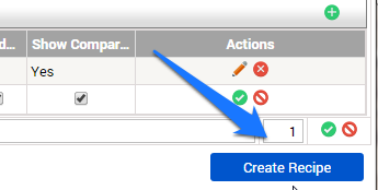
To insert more test steps, just enter the data in the same manner as done previously. When finished creating the test steps, click on Create Recipe to finish the recipe creation process.
Figure 107: Recipe – Create Recipe Icon
A success message should display at the top of the page, and Measurement will load all manual recipes including the one just created:
Figure 108: Recipe – Create Recipe Success Message
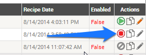
With the recipe stored in Measurement, it now needs to be enabled.
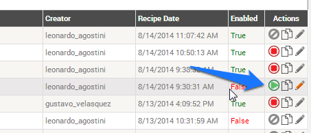
To enable a recipe, click the Enable icon in the Actions column on the recipe row.
Figure 109: Recipe - Enable
Measurement only accepts one active recipe per Process and Part Number. There can be multiple enabled recipes from different Part Number and Processes, but only one per each combination.
Clone an existing recipe
One of the features of Recipe Maintenance module is to clone an existing recipe.
This can be useful when there are different steps from the same recipe that vary per part number, or to forgo having to add all the specifications when most of the steps from different products are the same.
Due to traceability constraints Measurement does not allow editing a recipe that was used to process a unit. In order to change this, the creation of a new one based upon a used one is required. To achieve that, clone the recipe and change what is needed. If the Part Number and Process are kept the same from the older one, the Revision number will be incremented.
When enabling the new recipe, the old recipe will be automatically disabled, and will not be usable anymore.
To clone a recipe, click Clone under the Actions column of the respective recipe.
Figure 110: Recipe – Clone Icon
After selecting Clone, the fields containing information from the cloned recipe are for editing.
Click the Expand icon at the first column to see the Test Group and the Create Recipe button.
To create a new recipe based on the last (cloned) recipe with changes on test group for test steps, modify the values and select the Create Recipe icon.
Figure 111: Recipe – Example of Creating New Recipe from Clone
Both recipes are now shown with the same version but different Revision numbers.
Figure 112: Recipe – Original and Cloned Examples
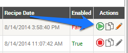
Notice that the new recipe is not enabled, so click on Enable.
Figure 113: Recipe – Enable Icon
After selecting Enable, note the original recipe is no longer enabled, given only one enabled recipe per Part Number/Process combination is permitted.
Figure 114: Recipe – One Enabled Recipe
To create a recipe with a different part number so as to keep both a recipe and its clone enabled, change the part number or process and click Create Recipe.
Figure 115: Recipe – Two Enabled Recipes
Both recipes are now Enabled.
Enable / Disable a recipe
When creating a recipe, it is not available to test units until it is enable. This design is in place to avoid having to complete the recipe creation at once, and to allow for the opportunity to review a recipe before any operators begin using it.
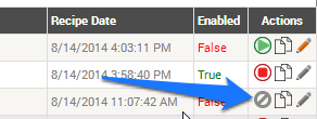
A created and enabled recipe can run tests. The recipe may be disabled up until a unit is tested using the given recipe.
A recipe can be disabled in two situations: (1) when there is no unit tested using this recipe; and (2) when there is a new recipe from the same process and Part Number.
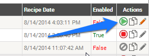
Users cannot enable a recipe of a newer revision.
Figure 116: Recipe – Newer Version Not Enabled
Figure 117: Recipe – Disable Older Version
Users cannot enable a recipe when another recipe is enabled that is being used to process a unit.
Figure 118: Recipe – Enable Icon not Available for Recipe In-Use
Manual Test Log
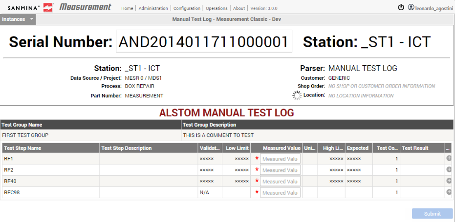
Manual Test Log feature is to allow non-automated test equipment data to be manually collected based on a created test recipe.
Using the manually input test data, Measurement is able to use configured Test Station to communicate with SFDC, and use a data collector associated with this test station to pass the serial number through the SFDC flow.
To execute a manual test log in Measurement, first choose a parser that supports the Checklist feature. To check this, expand the parser information and verify if the checklist property is marked Yes.
Figure 119: Manual Test Log – Checklist Value "Yes"
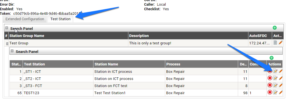
After selecting a checklist parser, choose which test station to use for performing the checklist operation on SFDC.
On the Test Station tab, expand a Test Group and choose a station to process the manual checklist entry. Click the respective Generate Testlink button under the Actions column to generate a link to direct access checklist page with this parser and station selected.
Figure 120: Test Station Tab
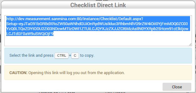
After selecting the Generate test link button, a popup with the direct link will appear. Please note this is a permanent link. It is not necessary to repeat the process again to access this checklist module with this parser and test station selected.
Figure 121: Checklist Direct Link Pop-up
Open another tab in the browser or use this current tab and paste the generated link. Users will be prompted to login with their badge number and password.
Figure 122: Badge and Password Login
Logging in directs users to the checklist module. Parser and station information will already be loaded.
Figure 123: Checklist Module
After entering a Serial Number, Measurement checks if this serial number sits on the current location used by the device associated with this station.
Figure 124: Serial Number Entry
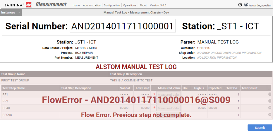
In case the serial number is not on the location associated with the device, users should see a flow error message on their screen.
Figure 125: Serial Flow Error Message
No error message appears when the serial number is on a location associated with the device. Select Setup.
Figure 126: Manual Test Log Setup
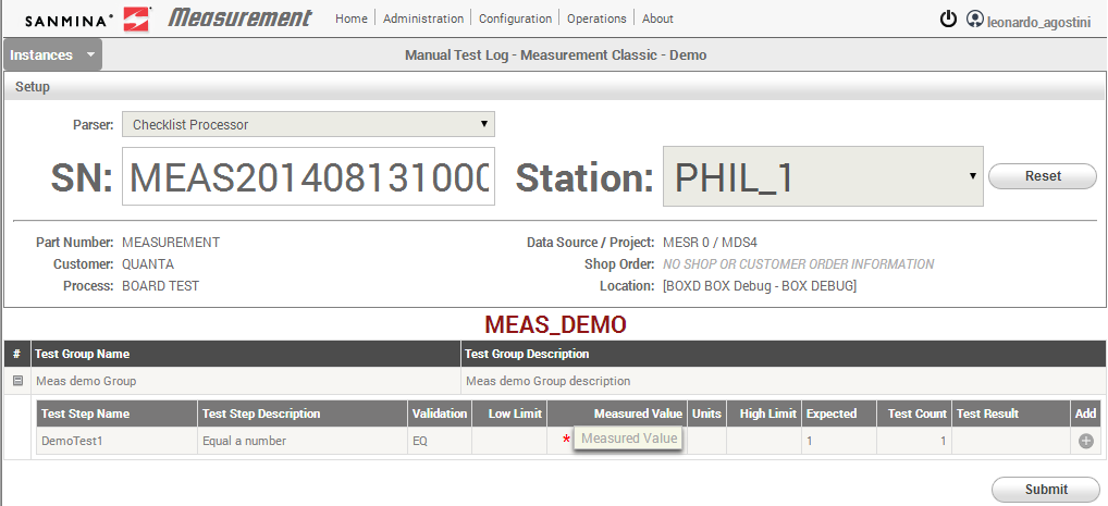
The recipe is loaded and ready to receive test data.
Figure 127: Checklist with Recipe Information
Users can manually input measured values into Measured Value Field.
Figure 128: Measured Value Field
On the left is the Validation field, which represents the comparator for the measured value. Also, Low and High Limits are given (when available, depending on the Validation type). All mandatory fields are marked with a red asterisk in front of the required field.
After inputting a value users can verify in the Test Results whether the measured value matches the expected value. When Test Results are NOT EVALUATED, Measurement only evaluates the result where the recipe was created with the Evaluate option marked.
Figure 129: Passed Test Result
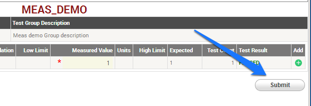
After inputting all required Test step values, click Submit.
Figure 130: Submit Button
After clicking on Submit, a success message will display.
Figure 131: Manual Test Success Message
This completes the manual input log, and the screen is ready to receive the next serial number.
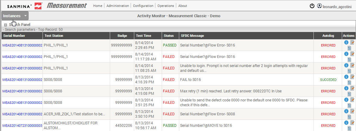
This tested serial number result is available from the Activity Monitor including its result from SFDC.
Figure 132: Activity Monitor Results Log
Monitoring
Activity Monitor
The activity monitor shows all the units that have been processed by the Parsers. In this module, all the details related to the serial numbers (activities) can be reviewed. This information includes parametric data information, stations where a unit was tested, activities that were sent to SFDC successfully and/or waiting to be inspected, and activities able to be reprocessed.
Users can set multiple activities with SFDC errors to be reprocessed. Also, there is a link between the serial number being shown and MESWeb. The user can click on the serial number link and Measurement will open MESWeb Unit History report.
To access the Activity Monitor page, go to the Operations menu and click on Activity Monitor.
Figure 133: Operations Menu – Activity Monitor
List activities
When the activity monitor page is opened, Measurement loads the first 50 activities from the instance. This includes all customers and parsers ordered from the latest activities.
The columns and their respective definitions are as follows:
- Serial Number: The processed unit serial number. This also links to MESWeb Unit History report related to this serial number.
- Test Station: The configured Measurement Test Station which processed this serial number on SFDC.
- Badge: The operator used to communicate in SFDC.
- Test Time: The time this unit was processed in Measurement.
- Status: The overall test status. Possible statuses are
- PASSED: Unit has passed the test.
- FAILED: Unit has failed the test.
- KNOWN GOOD: It is an activity of a golden unit: a perfect unit that ensures the test equipment is working well.
- ABORTED: Test was aborted but an activity could be generated.
- IGNORED: Test data is invalid but an activity could be generated.
- NOTEST: Test is incomplete due to temporal or equipment limit conditions.
|
- Autolog Message: A message, from SFDC or Measurement itself, indicating the current status of the unit on production. This refers to an error that occurred after parsing the activity or indicating that the parser is waiting for an external action before continuing the SFDC communication.
- Autolog Status: The status of the parser communication with SFDC. Possible statuses are
- SUCCEEDED: The communication was successfully performed and SFDC has accepted all commands. It does not necessarily mean that the unit has passed.
- ERRORED: There was an error with SFDC communication. It may be caused by Flow Error, Device In Use, or another input error. The Autolog Message column displays the SFDC message.
- WAITING INSPECTION: Activity has been successfully processed and is waiting to be inspected before SFDC communication is performed.
- INSPECTED: Activity was inspected and is waiting for its parser to process it the next time it runs.
- PENDING: Activity is waiting for its parser to process the next time it runs.
- MANUALLY SKIPPED: Communication was not performed due to an action a user has made, such as skipping the activity on Inspection Review.
- AUTOMATICALLY SKIPPED: For some reason, parser did not permit SFDC communication to occur. Generally, this issue is specific to a customer implementation.
- NOT APPLICABLE: Activity is not eligible to be logged on SFDC. The main reason is that its test station is not configured to communicate with SFDC.
- BUFFERED: SFDC communication is in the queue to be performed.
- IGNORED: Activity has invalid test data, or test station is not properly configured to move on to SFDC.
Figure 134: Activity Monitor
Search activities
Activity Monitor has a search function. To search for a specific test result(s), expand the Search Panel on the top of the Activity Monitor’s list.
Figure 135: Activity Monitor Search Panel
Users can use one or more filters for the search. The possible filters are
- Customer: Specific customer activities are filtered. Only one customer is allowed.
- Parser Name: Only activities processed by the selected parser.
- Top records: The latest selected number of activities.
- Station Groups: Only the activities processed using the selected station groups. May select multiple station groups.
- Test Stations: Only activities processed using the selected stations. May select multiple stations.
- Autolog Status: Only the activities where communication to SFDC status equals the selected value.
- Start/Stop: When enabled, Measurement reloads this search based on the number of seconds set on this field.
- Serial Number: Search for activities from a serial number specific. Does not perform partial text search.
- Autolog Message: Search for a specific part of the message. This type of search can a few moments to pull up results.
- Status: Filter activities which have their overall test status equal to the selected one.
Get direct link
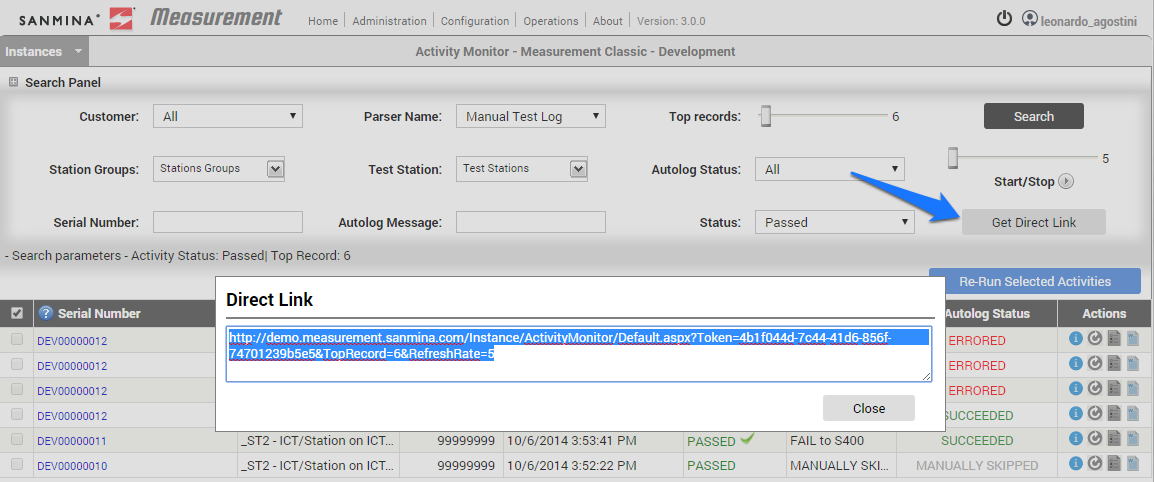
Measurement Activity Monitor provides a mechanism to create a permanent link with the configured search filters set when the link was created. Only the Top records and Start/Stop filters are valid.
When a combined filter that that runs frequently has been created, users can set these filters, create a direct link and next time there is a need to see the result, users can directly enter on the application using this generated link.
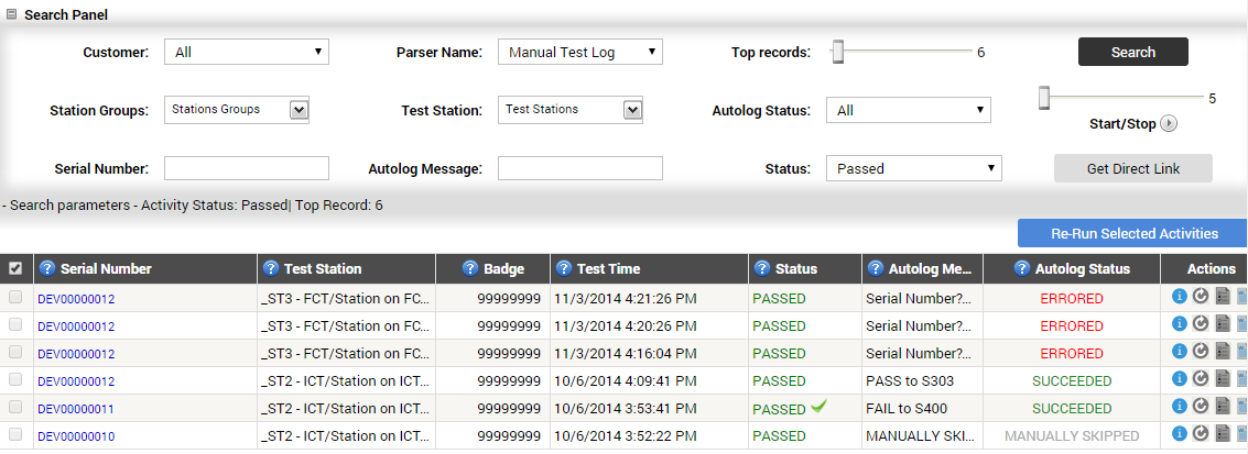
In order to create a link with a pre-configured search, from the Activity Monitor page set the filters. In the example given below (see fig. 137), the latest six activities have been selected.
Figure 136: Filtered Activity Monitor Example
With the Get Direct Link button selected, Measurement generates a link that will be saved and opened in a pop-up window.
Figure 137: Direct Link URL Window
How to see activity details
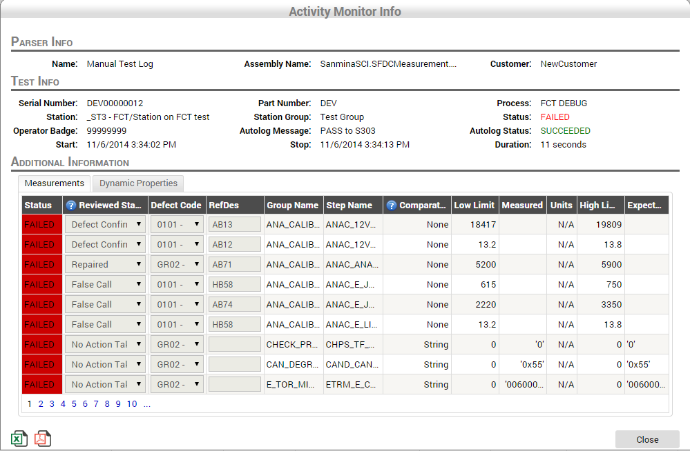
Measurement was originally designed to collect parametric data from test results. To see all information collected and processed by Measurement from a specific serial number, click on the More Details button under the Actions column for the respective activity row.
Figure 138: More Details Icon
Measurement opens the activity monitor info page from the respective selected activity.
All information such as process time, AutoSFDC status, duration, all parametric data collected, and status are shown.
Figure 139: Activity Monitor Information Page
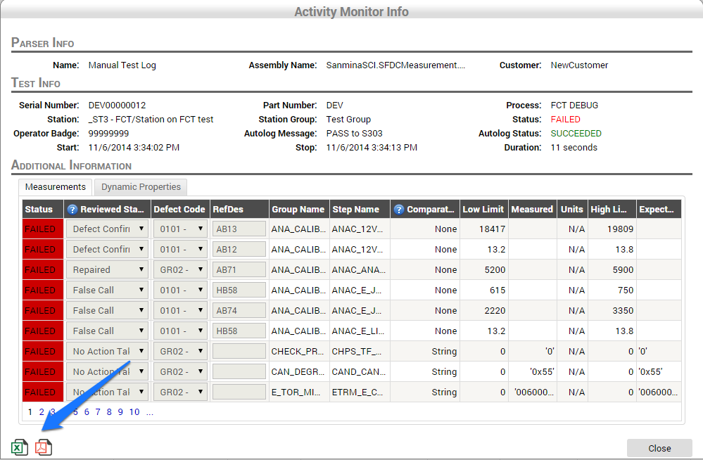
Additionally, the information can be exported in Excel or PDF format by selecting the respective export format icon located at the bottom of the page.
Figure 140: Export Icons
Re-run a process failed activity
This feature allows the operator to reprocess an activity that failed while communicating with SFDC. It is known that SFDC could be unresponsive due to maintenance or a shop floor update process. During this operation, Measurement is designed to retry temporarily to reestablish communication; if communication is not reestablished, the Autolog status is set as ERRORED.
Operators can manually trigger a process to allow Measurement to retry to send data to SFDC. This feature is allowed to be performed only for ERRORED activities. This operation can be performed from the Activity Monitor by selecting the Re-Run Activity icon.
Figure 141: Re-Run Activity Icon
After the Re-Run Activity icon has been selected, Measurement will change the Autolog Status to PENDING. On the next parser iteration, the activity is loaded and processed within SFDC. The status will change according to its processing result.
Figure 142: AutoLog Status Change
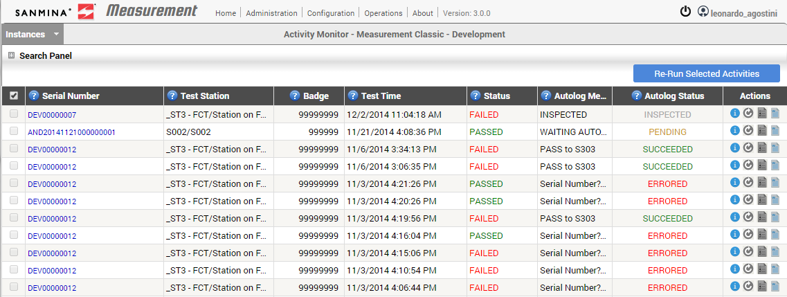
Additionally, multiple ERRORED activities can be selecting for reprocessing. In this case, mark the activities to be reprocessed on the first column checkbox and click Re-Run Selected Activities at the top of the Activity Monitor page.
Figure 143: Entry Checkbox
Figure 144: Re-Run Selected Activity Function
Measurement will set all selected activities to have the Autolog Status as PENDING and the parser will reprocess them at the next iteration process.
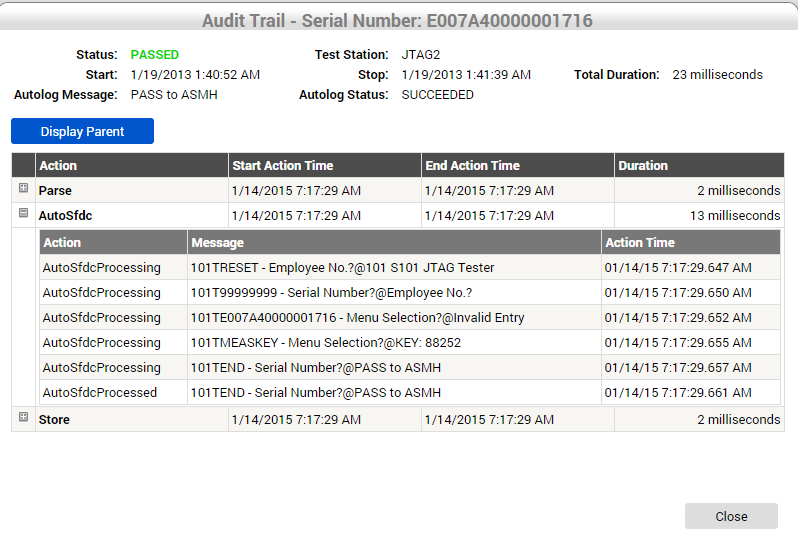
See audit trail for an activity
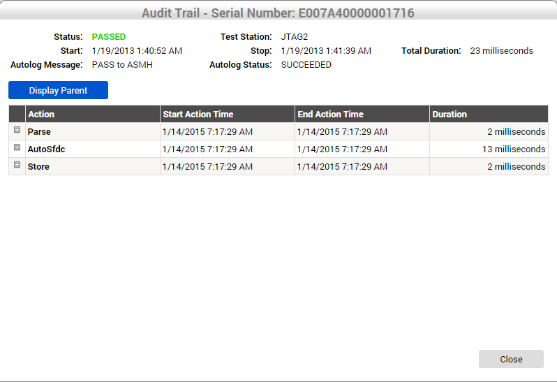
Audit Trail is the module where one can view diagnostics for an activity process workflow. The duration for each process step and their result can be extracted.
To see an audit trail for a specific activity, click on the Audit Trail icon at Actions columns from the respective activity row.
Figure 145: Audit Trail Icon
Measurement opens the Audit Trail screen containing the activity information.
Figure 146: Audit Trail Window for Selected Activity
Each one of the action items are a step processed on the Parser. Expand the item to see detailed information with start and end timestamp values.
On the example below one can see all communication history between Measurement and SFDC for this serial number including prompts, commands, and responses with their respective time.
Figure 147: Audit Trail with Communication History
Inspection Review
This module provides the user with the capability to determine whether a test result PASSED/FAILED is genuine, thereby avoiding wrong results (e.g., a test result wrongly assigned due to test error) that affect the manufacturing process and quality metrics.
When a Parser is configured to run with the Inspection Review property active, it will not execute the Autolog function, it will store all serial number information (such as unit information, test result, and parametric data), set the Autolog Status to WAITING INSPECTION, and wait for the user(with grants to perform this action) to inspect and submit the result. Users then determine what to do with the steps processed by the parser (passed or failed ones) such as, choosing defects, confirming real fails, or skipping the test step.
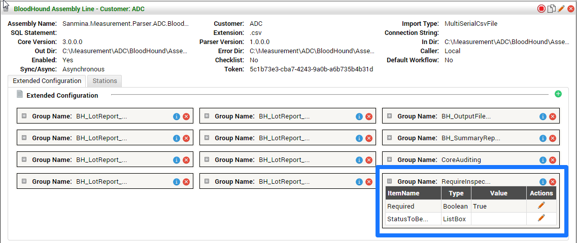
To make sure the parser is configured to support manual inspection, verify it is assigned the RequireInspection Configuration Group, with the Require property set to True.
If this configuration is not assigned, this group can be added and set the Required property to True. The RequireInspection group is a Measurement build and does not need to be created.
Figure 148: Require Inspection Configuration Group
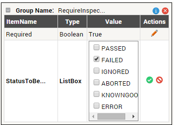
Additionally, users can specify which original status they want to manually inspect. If there is a preference to inspect only those that FAILED, in the StatusToBeInspected property check only the FAILED status as in the following image:
Figure 149: FAILED Manual Inspection Selected
Submit an inspected activity
To review and submit an activity, go to Activity Monitor and find the serial number waiting to be inspected. Notice that the Inspection Review button (paper icon on Actions column) is enabled.
Figure 150: Enabled Inspection Review Icon
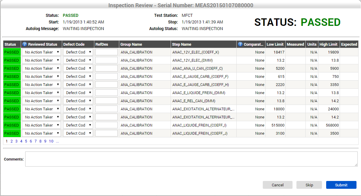
After selecting Inspection Review, Measurement will open a window with all parametric data and test result statuses opened for changes.
Figure 151: Inspection Review Results
For each test step, users can change the Reviewed Status, assign a Defect Code for the test step in case a FAILED status is set and optionally add a reference designator to the step. If users do not select a Defect Code, the Default Code configured for the station will be used.
Additionally, any comments added in the Comments field are stored on the serial number within SFDC are visible in the MESWeb Unit History report.
Figure 152: Inspection Review of Failed Status
Note on the image above that since a PASSED test step was changed to a Defect Confirmed status, Measurement changed the unit test status to FAILED.
After clicking on Submit, Measurement will store the changed information and set the Autolog Status to PENDING. This will allow the parser to process this activity in the next iteration process.
Skip an inspected / non inspected activity
Following the same steps from Submit an inspected activity case, users can skip an activity to perform the SFDC action and not send data to SFDC.
After reviewing the Inspection page from a unit, users can simply select Skip. This will change the Autolog Status to MANUALLY SKIPPED and no SFDC communication regarding this activity will be performed.
Log Viewer
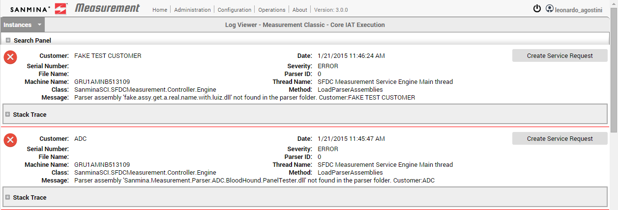
Log Viewer is the module where Parser processing deviations can be tracked. This is generally used for troubleshooting when in the even of an abnormal flow, invalid data received, or any kind of system malfunction behaviors.
Based on this module the user in charge is able to identify any parser error or units not being processed in Measurement, and can quickly determine, by the error message, if support team escalation is required. Log Viewer also provides a shortcut feature to open service requests to the Measurement Support team with proper error descriptions based on the error log.
To access Log Viewer application, click on the Log Viewer item under the Operations menu.
Figure 153: Operations Menu – Log Viewer
List log entries
When the Log Viewer page is opened, the latest 30 entries are loaded into a list, providing the following information:
- Customer: The customer set on the parser when the respective log was generated.
- Serial Number: The serial number being processed when available.
- File Name: The filename used for text file parser processing when available.
- Class: The Measurement object in which this error was placed.
- Message: Technical or customized message regarding the given unexpected behavior.
- Date: Date and time the given action occurred.
- Severity: Type of action/behavior of the given entry.
- Parser ID: The parser identification that generated this error.
- Thread Name: SO Thread name that placed the given error.
- Method: The Measurement object class name in which this error was placed.
Figure 154: Log Viewer
Search on log items
It is common to have some information when starting to troubleshooting, such as the production line, customer or product, and serial numbers that were not processed correctly for unknown reasons.
The Log Viewer module offers a few filters to help find the exact error blocking the unit to be processed. The filter fields include the following:
- Serial Number: The serial number being tested.
- Severity: The type of error.
- Customer: The active customer’s list being used on parsers.
- Top Records: A limit results on the screen. The higher the number, the greater the time the search will take to generate results on the screen.
- Date Range: Date and time range to search the logs when they occurred.
- File Name: The filename being processed which places the error.
- Message: The text message produced by the application. This field generally decrease the performance of the search operation.
- Start/Stop: Used to trigger the search operation between a set number of seconds.
Figure 155: Log Viewer Search
When Search is selected, Measurement loads the log entries according to the filter criteria.
To erase the filter, clear all fields and click the Search button.
Create a Service Request based on a log entry
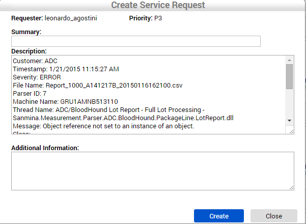
In case users find a log entry that they cannot solve or they identify it is an application technical deviation, they can use this log entry to open a service request. Log Viewer application offers an easy way to do that. In front of each ERROR type log entry, there is a Create Service Request button. When users select this option, Measurement loads a Submit Form to create a service request, using the logged in username and the log details as an SR description.
Figure 156: Create Service Request Form
When Create is selected, Measurement opens a service request to the Measurement support team, and users will be returned to Log Viewer list.
About
The About section is an informative section that describes the Measurement evolution tool and gives support team contacts.
Release Notes
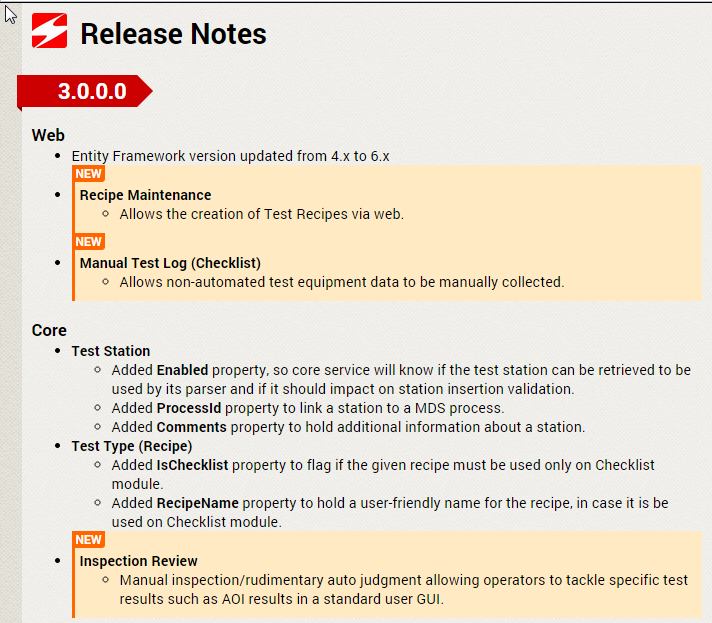
Release notes is a history board from all changes that have been made to the tool.
To access Release notes section, click on Release Notes under the About menu item.
Figure 157: About Menu – Release Notes
Measurement loads a new window containing the release notes content separated by version.
Figure 158: Release Notes
Revision Log
| Revision | Date | Editor | Comment |
| v 1.0 | April/08/2014 | Elaine Fonaro | This is the first revision of Access Control: User’s Guide |
| Feb/19/2015 | Dane Parker | Grammatical and mechanical edits | |
| 04/29/15 | Dane Parker | Edited Content | |
| 04/30/15 | Elaine Fonaro | Final Review and WIKI |
