SOP-42Q-MES0049 SMT Part Traceability
Contents
EZ Picklist
Convert SMT Program to Picklist
Figure 1: Convert SMT Program to Picklist – Main Menu
- Select “EZPicklist” menu under “SMT Machine” main functional module.
Select SMT Program File
Figure 2: SMT Program File Selection Window
- Click “Select Picklist” button to locate the desired material placement file.
- Select the SMT program file name. Please refer to SMT job profile which prepared by SMT Engineer for the file name for each
SMT machine.
- Click “Open” button. Details of the picklist will be shown.
Figure 3: Full Picklist Details Window
All SSCI part number, station, feeder, count, and designator are encoded in SMT placement program which were prepared by
SMT Engineer.
Material(s) Selection for Traceability in EZ-Picklist
Figure 4: Material(s) Selection Option in EZ-Picklist
- Select the 1st production side and/or 2nd production side (as per picklist setup for production environment):
- In case the selected picklist is intended for a double-sided board which have one or multiple common materials in both sides,
refer to green-framed items in below figure, there are 2 items of the same Part Number in the picklist, which means, this is a
double-sided board, side 1 and side 2 have one common material.
- To make no confusion during the production for such boards, we need to configurate which item needs to be used in which
side. As common material items share the same part number but match with different board numbers, we can simply
match board numbers with sides to realize the configuration of items to sides.
Figure 5: Double sided board with the same material handled in the same station
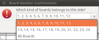
- Click on 1st Side or 2nd side option in this instance, a dialog box like below will prompt:
Figure 6: Board number confirmation
- This dialog box allows user to perform board-number-to-side mapping for common material(s). There will be 3 options
available in the drop-down list, refer to below figure:
- Board Number Goup 1: Board numbers of one side, auto detected and grouped by system. For normal panel
production(with all boards up or down), user can select this one.
- Board Number Group 2: Board numbers of the other side, auto detected and grouped by sytem. For normal panel
production(with all boards up or down), user can select this one.
- All Boards: With all board numbers included, that is to say, boar number group 1 plus board number group 2.
This option is designated for mirror-board production, with some boards up and some boards down and all are populated at
the same time.
- Simply select an option as per actual production and click on OK to confirm. Take note that board numbers for the other side
will therefore be confirm and no further confirmation needed once one is done.
- In case the selected picklist is for single-sided board, no confirmation is needed and system will simply check materials for
the selected side as per default configuration.
- Select the High Value option, Lead Free option checkbox associated to each individual material part number if required.
Figure 7: Material(s) Sending Option in EZ-Picklist
- Click “Send” button to send the picklist to PTS server.
Confirm the Picklist Successfully Generated
Figure 8: Successful Prompt upon Completed Picklist Conversion
- After the picklist is submitted to server, message prompt “Complete” will display as shown in Figure 6.
- Click “Confirm” button to confirm it.
Generate Loading List
Figure 9: Loading List Option in EZ-Picklist
- Click “Loading List” button to send the picklist to default path: C:\pts\loadinglist\ (Windows); /temp/loadinglist (Linux) .
Note:
- Default path for Loading List report is customizable. Local plant can simply contact PTS team to do the
customization.
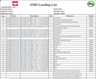
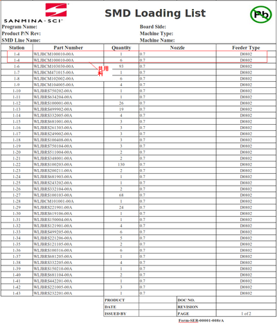
- There are two available templates for Loading List report, refer to below Template 1 and Template 2. Template 1 is the
default one, local plant can also contact PTS team to switch to Template 2.
Figure 10: Available Loading List templates
| Template 1(Default) | Template 2(Adding Nozzle Info) |
Please be noted that this Surface Mount Devices (SMD) Loading List cannot be used as a control document without stamp/sign
by authorized personnel defined by plant such as SMT production line supervisor/team leader. This is designed to be used for
materials loading reference only.
Figure 11: Confirm the Loading List Successfully Generated
- After the Loading list is generated successfully, message prompt “Complete” will display as shown in Figure 8.
- Click “Confirm” button to confirm.
SMT Comparison
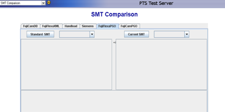
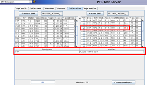
This module is designed to compare standard SMT program and current SMT program, which makes it easy for user to find out
the differences between two programs and eases the operation.
SelectSMT Comparison from the main menu of PTS Web, a window shows up, refer to below figure:
All available SMT machines are shown in tabs and there are two grids displayed under each tab for user to make comparison
the programs of the selected machine type:
- Select correct machine tab.
- Click Standard SMT button, system will pop up one dialogue box asking user to select one file (make sure the file user
selected matches with machine type)
- Then click Current SMT button, select current SMT program for comparison.
- After both program selected, system will compare them and show differences to user. Refer to below figure:
- As above shown, the modified value is marked with red in Current SMT table.Corresponding checkbox for the item will be
ticked automatically.
- Designator: List out designators that has been modified.
- Modified: Display original data and new data. (E.g. X_Axis: -69.93/-69.9, ‘-69.93’ is original data, ‘-69.9’ is new data.)
- Click Comparison Report button, a report will be generated under C:\pts \report to log what has been changed .
SMT-BOM Comparison
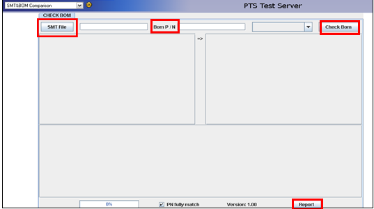
This function is used to compare picklist whether existing in BOM file.
Select SMT & BOM Comparison from the main menu of PTS Web, a window shows up, refer to below picture:
- Click SMT File button, system will pop up one dialogue box asking user to select appointed Ezpicklist file.
- Input correct BOM part number into BOM P/N text box, then press Enter key.
- Select correct ECN number from pull down list.
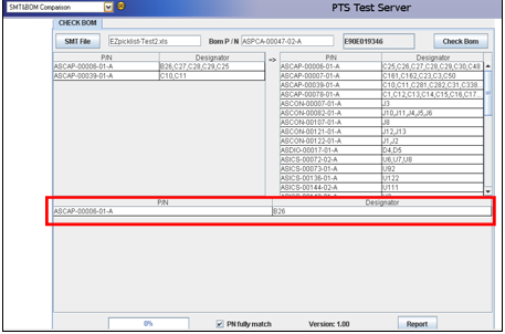
- Click Check BOM button. If there is any error record in BOM file, the error message will show in the table right below, refer to
below picture:
- Click on Report button, an EZpicklist excel file will be automatically genterated and saved under the default path:
C:\pts\report.
Show BOM
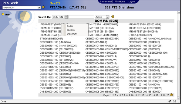
This module allows user to view BOM, disable BOM or enable BOM.
Select Show BOM from the main menu of PTS Web, below picture shows up:
- All BOM P/N(ECN) in the system are listing out in pages.
- User can search a BOM by BOM P/N or BOM ECN, and/or by Active or Disabled.
- Right click one selected item, a menu will be shown(refer to above figure):
- Disable: Allow user to disable the selected BOM P/N or BOM ECN.
(Note: on online ECN can't be disabled and system will prompt a warning message accordingly)
To enable a disabled BOM, user can:
1. Search the BOM by Disabled and click on Go button, all disabled BOM will be displayed;
2. Right click on target BOM and select Enable.
- Deviation: This option redirects to Deviation Note Report page and allows user to add or review the deviation records.
- Show BOM: This option allows user to view all existing items under the selected BOM. Refer to below figure:
1. Click Send button, system will redirect to File Archive page which allows user to export the BOM.
2. Cancel takes user back to previous page.
Compare BOM and Picklist
This module is designed to verify if designators in BOM are consistant with the ones in SMT program and list out the
differences.
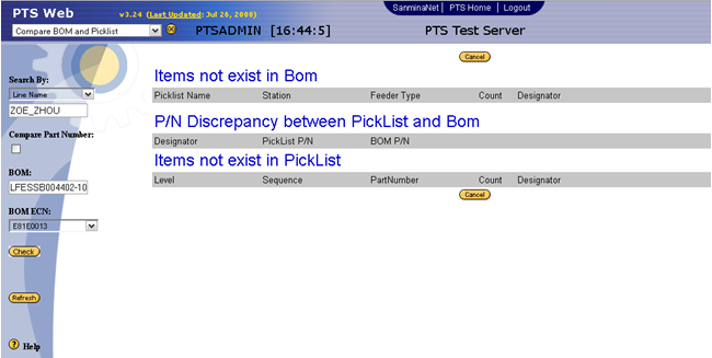
Select Compare BOM and Picklist from the main menu of PTS Web:
Currently, system provides two methods to search comparison results. Search by Line Name or Picklist Name. Details are
explored below:
Search By Line Name
- Input Line Name
- Input BOM number into BOM textbox
- Select correct BOM ECN from BOM ECN drop-down list.
- Click Check button. The results will be shown on the right. Above figure is an example of unmatched results.
- If BOM match with Picklist, screen will show as the following.
Note: Pay attention to Compare Part Number check box. This option is meaningless if user choose to search by Line
Name.
Search By Picklist Name
- Select and input Picklist Name
- Input BOM number in the BOM textbox
- Select a correct BOM ECN from the drop-down list
- Click on Check button.
Note: Pay attention to the Compare Part Number check box here, the result shown on the right will be of slight
difference with this option checked and unchecked. Refer to below figures:
| Compare Part Number Checked | Compare Part Number Unchecked |
PN Extra Info
This module allows user to flag the high value material and define whether or not to track and show orientation picture for a
particular material during the process of material loading.
Prerequisites:
- Please sent " Track all Components=Yes " under System Setting page on PTS Web.
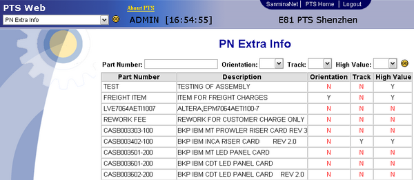
Select PN Extra Info from the main menu of PTS Web, below picture shows up:
- User can perform search by inputting target part number and/or defining parameters (Orientation, Track, High Value);
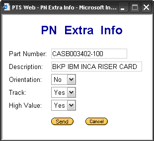
- Select one item and click on its part number, a window will pop up, refer to below figure:
- Part Number: The part number selected by user. Display only.
- Description: Description of the item selected by user. Display only.
- Orientation: Whether or not to show the orientation picture when loading this material. select Yes or No.(Note: This
option will be disabled only when " Show Orientation Picture=Yes" under System Setting page.
- Track: Whether or not to track the material. Select Yes or No.
- High Value: Define whether or not the selected item is a high value item. Select Yes or No.(Note: This option will be
disabled only when "High Value Mark=Yes" under System Setting page.
- Send: Click this button to save the configuration.
- Cancel: Click this button to go back to previous window without saving.
Feeder Registry
Supervisors and administrators can create, change, and review history using the Feeder Registry portlet:
Creating a New Feeder
- In the Feeder Registry portlet, click Create Feeder.
- In the Create Feeder pop-up window, Select the Feeder Type, enter the new Feeder Barcode, and the Number of Feeder(s). Then click Create.
- Enter the Feeder Name in the Search text field and click the search icon to search. The new Feeder should now display in the search results.
Deleting a Feeder
- Enter the feeder barcode into the Search field and click the search icon to pull up the feeder in the search results.
- Check the box of the feeder.
- Click Delete.
Feeder Rework
Supervisors and administrators can rework feeders by using the Feeder Rework portlet by following the instructions below:
- In the portal, access the Feeder Rework portlet: Production > SMT Machine Part Traceability > Feeder Rework.
- Enter the full feeder name or scan feeder barcode then press enter or click on the next field.
- Change the maximum usage depending, maintenance period, minimum alarm usage and minimum alarm usage and minimum alarm maintenance period on feeder status.
- Click Add on the right panel.
- Key in Service Description then click Create on the call out page.
- Click Cancel button on the call out page.
- Select the Service Description from the drop down list, key in Remark then click Send on the right panel.
- Click Refresh.
- Click Print. Then click the ? on the left panel.
Feeder Type Registry
Supervisors and administrators can create, change, and review the feeder type history by using the Feeder Type Registry portlet.
Creating a New Feeder Type
- From the Feeder Type Registry portlet, click Create Feeder.
- In the Create Feeder pop-up windown, enter Feeder Type, Feeder Barcode, and Number of Feeder(s). Then click Create.
- Enter the apropriate values in the Type Regulation, Max. Usage, Maintenance Period, Min. Alarm Usage, Min. Alarm Period fields. Click Update.
Changing a Feeder Type
- Search for the feeder type to be changed by entering the feeder type or barcode into the search field and clicking the search icon.
- From the search results, check the box of the feeder type to be changed. Click Update.
- The Max. Usage, Maint. Date, Full Maintenance Date, and Maint. Period fields can now be changed.
- After the changes have been made, click Update.
Workstation Type
Under this module user is allowed to add/delete/change a workstation type.
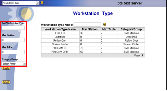
Select Workstation Type from the main menu of PTS Web, a picture shows up as below:
- To Add a workstation type:
- Input workstation type name inAdd Workstation Type textbox.
- Input Max Station number in the textbox.
- Input Max Table number in the textbox.
- Select one Category/ Group from the drop-down list
- Click on Create button to add workstation type.
- To Search a workstation type,input Workstation Type Name in the textbox and click on GO button.
- To change or delete a workstation type:
- Click one Workstation Type Name, system go to Workstation Type Maintenance page allowing user to modify relevant
parameters of this workstation type.
- Click on Change button to save new configuration.
- Click on Delete button to delete this workstation type.
JIG Registry
Prerequisites
- Set production offline.
- This function only works on request. Please set “Jig Control = Yes” in System Setting page
before using this function.
Overview
This function will support tooling has been installed in SMT machine correctly for a specific product.
The following is an example, which shows the user how to operate this function:
Operations
Set Parameter
Please set “Jig Control = Yes” in System Setting page before using this function. (Note: This
part only allow administrator to change it.)
- Select Administration > System Setting from main module.
- Change Jig Control parameter to “Yes”
- Click “Send” button to save change.
Jig Maintenance
To begin to use Jig function, user needs to set Jig in this module first.
Jig Maintenance List
Add Jig Maintenance
Jig Picklist Mapping List
Jig Picklist Mapping Addition
Load/Unload Jig Tool
This function is used to load jig for next scanning board.
Prerequisites:
- Set "Jig Control=Yes" under System Setting page;
- Jig barcode has been created;
- Mapping has already been created for this barcode.
At PTS Web, select Load SMT Tools from the main menu up on the left:
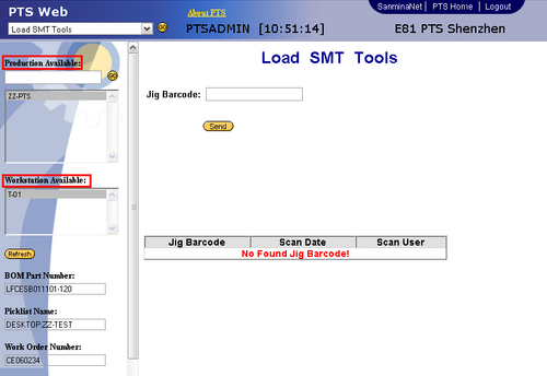
1. Select Producion (line) Available and Workstation
Available.
2. BOM Part Number, Picklist Name, Work Order Number will be display only.
3. Input corresponding jig barcode in Jig Barcode textbox.
4. Click on Send button, system will auto verify whether the jig barcode can be loaded to the selected workstation based on
defined mapping. If the jig barcode is correct, it will then be loaded successfully and displayed at the table below. The table
shows current jig barcode only.
5. An error message will pop up if system fails to load jig, details please refer to below table.
6.To unload jig, please click on corresponding jig barcode and a dialogue box will pop up asking user to confirm the operation.
Click OK to unload, and Cancel to go back to previous window.
Error Messages for Load SMT Tools
| Error Message | Reason | Solution |
|---|---|---|
|
Jig not matched! |
Maping already existed, but not matched with the jig barcode entered | Check it in PTS Web>Jig Maintenance or change to correct jig barcode |
| Jig is now in use! | This jig is currently used by another workstation. | unload this jig from the workstation where the jig is in use or choose another jig with the same mapping. |
| Jig not required in this workstation! | No need to verify jig barcode in this workstation. | It will not affact scan board. User can scan board normally. |
| Jig not exist | The jig barcode user entered doesn't exist. | Re-enter a correct jig barcode or create a jig barcode with the entered name. |
Scan Board With Jig
If no jig is loaded for current workstation, the scanning will be failed.
Machine Registry
Supervisor, administrator, and production users can change the machine registry record values using the Machine Registry portlet:
- From the Machine Registry portlet, click Create.
- Enter the Machine No., Machine Barcode, Machine Ownder, Description, and select the Machine Type. Then click Update.
- Search for the machine type or machine barcode by entering the type or barcode of the machine into the Search field and clicking the search icon.
- Select the machine type or machine barcode from the results.
- Click Update[?] to change the machine registry value. When changes are complete, press Update to apply the changes.


