Difference between revisions of "SOP-42Q-MES0024 Traceability Setup"
m (Marisol vargas moved page SOP-42Q-MES0024 Production Setup to SOP-42Q-MES0024 Traceability Setup: Revision Control is been renamed.) |
Helena wang (talk | contribs) |
||
| Line 422: | Line 422: | ||
| | ||
| − | === <span class="mw-headline" id="Workstation_Setup"><span class="mw-headline" id="Workstation_Setup"><span class="mw-headline" id="Workstation_Setup"><span class="mw-headline" id="Workstation_Setup">Workstation Setup</span></span></span></span> === | + | |
| + | === <span class="mw-headline" id="Workstation_Setup"><span class="mw-headline" id="Workstation_Setup"><span class="mw-headline" id="Workstation_Setup"><span class="mw-headline" id="Workstation_Setup"><span class="mw-headline" id="Workstation_Setup">Workstation Setup</span></span></span></span></span> === | ||
This module allows the user to set up the scanning behavior and scanning rules for each defined Workstation under the associated Production Line. | This module allows the user to set up the scanning behavior and scanning rules for each defined Workstation under the associated Production Line. | ||
| Line 447: | Line 448: | ||
Fill in "Barcode Regulation" based on the serial number mask which is applied on each PCB serial number barcode label. If blank, no serial number will be validated for all PCB serial scanning. | Fill in "Barcode Regulation" based on the serial number mask which is applied on each PCB serial number barcode label. If blank, no serial number will be validated for all PCB serial scanning. | ||
| + | |||
| + | For example: The plant set the Barcode Regulation: '''^JZ[0-9]{6}$'''. Then the barcode can be '''JZ057867,JZ057868.''' {6} means the numbers of the characters.[0-9] means the characters can be numbers from 0 to 9. | ||
| + | |||
| + | | ||
2. '''Scanning Behavior: (Compulsory)''' | 2. '''Scanning Behavior: (Compulsory)''' | ||
Revision as of 01:55, 21 December 2021
42Q Home > Shop Floor Control > Production Control > Traceability Setup
Contents
- 1 SFDC Production Control
- 2 Traceability Setup
SFDC Production Control
As its name implies, the Shop Floor Data Collection (SFDC) system is responsible for the collection of data from the shop floor. The collected information is then stored in the Manufacturing Execution System (MES). Specifically, the real-time information collected by SFDC is utilized by Reporting and MES Web to create quality control reports. The SFDC system uses manual and automated barcode scanning to monitor and collect data for a product line or plant. Thus SFDC plays an important role in maintaining unit histories and directing product movement on the manufacturing floor.
The system provides Access Control between the modules of the application, including the functionalities of each screen. The current version has an SFDC Configuration page which provides access to all sub modules pages and their functionalities (view, add, edit, delete, print, and generate output file).
General Notes
- This Work Instruction is a basic general training guide and is not meant to teach the process flow for an individual plant or department functionality. Individual 42Q sites may have minor or specific process changes that will be documented at the site level.
Assumptions
- Availability of SMT material placement program (e.g. Fuji SMT job program) or Hand load material placement (e.g. Material items and associated reference designator under Hand load operation).
- Serial number printed on board prior SMT and/or Hand load operation process.
- Each SMT machine has been assigned a unique name for identification purposes. (i.e. Workstation name)
Prerequisites
1. Understand PTS terms definition from Glossary SOP-5-I-MES0044-C RA1 PTS Glossary
Overview
This overview explains the process for production setup in PTSWEB base on the following two different production setup scenarios:
Scenario 1
Production Setup for a new (or previous built) product item on a new shop floor production line, suggested following the steps below in PTS:
| 1.Convert and upload SMT Picklist into PTS. | Refer to ''SOP-5-I-42Q-MES0049-C RA1 SMT Part Traceability. |
| 2.Create a New Production Line. | Refer to 2.1 Create a New Production Line. |
| 3.Create all required Workstation(S). | Refer to 2.5.1 Create a New Workstation. |
| 4.Add the Workstations into the Production Line by sequence. | Refer 2.6.1 Add a Workstation into a Production Line. |
| 5.Define Workstation Process Sequence in a Production Line. | Refer to 2.7 Workstation Sequence. |
| 6.Define Workstation Parameters for each added Workstation(s). | Refer 2.8 Workstation Setup. |
| 7.Define Picklist for each above-added Workstation(s). | Refer 2.9 Define Picklist. |
| 8.Define Auto-Scan Mapping. (Optional) | Refer 2.10 Location Mapping. |
| 9.Set Production Online. | Refer 2.11 Set Production On/Off-Line. |
Scenario 2
Production Setup for a previous built production item on was previously built shop floor production line, suggested following the steps below in PTS:
| 1.Convert and upload SMT Picklist into PTS. | Refer to ''SOP-5-I-42Q-MES0049-C RA1 SMT Part Traceability. |
| 2.Define Picklist for each Workstation that corresponding to the associated Production Line. | Refer 2.9 Define Picklist. |
| 3.Set Production Online. | Refer 2.11 Set Production On/Off-Line. |
Note: This work instruction is a general training guide and is not intended to provide a shop floor production process flow for all individual plants or departments.
Note: Please avoid setting up a new assembly on any existing created production line in PTS. It is recommended to have a PTS production line naming set up for one specific assembly exclusively.
Traceability Setup
1. To access the traceability Setup page, navigate to Shop Floor Control > Production Control > Traceability Setup.
Figure 1: Traceability Setup
Figure 1- Traceability Setup.png
Create a New Production Line
Figure 2: Create New Line
1. Select Create Production Line.
2. Enter the new Production Line Name. (See the following section for naming format suggestions).
3. Select Create to confirm the addition.
Note the following naming conventions for the Production Line.
By Shop Floor Location
Format: Area Location + Production Zone - Production Part Number - Production Process - Production Side Area Location: F (Floor), G (Ground) Production Zone: Floor level or zone area in production either in alpha or number format. Production Part Number: as named.
Production Process: S (SMT), H (Hand Load)
Production Side: T (Top), B (Bottom)
Example: F2-ABC12345-S-T
Production Line for product ABC12345 top side SMT production at 2ndfloor.
By Production Process
Format: Production Process + Production Zone – Production Part Number – Production Side Production Process: S (SMT), H (Hand Load)
Production Zone: Floor level or zone area in production either in alpha or number format.
Production Part Number: as named.
Production Side: T (Top), B (Bottom)
Example: S2-ABC12345-T
Production Line for product ABC12345 top side at SMT Line/Zone 2.
Search a Production Line
Figure 3: Search Production Line
1. Enter the production line name or keywords in the Search Line Name field.
2. Select the line name from the list.
3. The related production line will be listed in Production Line Available text box.
Note: Input the first 1 or 4 keywords for the line name, then the line name will display.
Rename Production Line
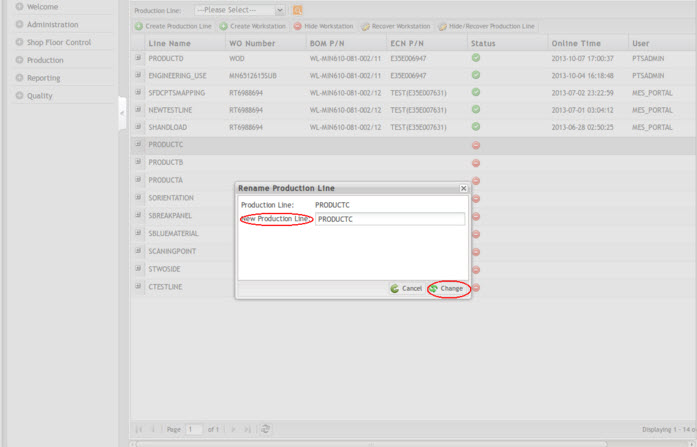
Figure 4: Rename Production Line
1. Select the production line from the Production Line list.
2. Open the pop-up menu by Right-Clicking, and then select Rename Production Line.
3. Enter the New Name in "New Production Line".
4. Select Change to rename the production line.
Figure 5: Rename Production Line Form
Note: The production line name can be changed only when the production line is in offline mode.
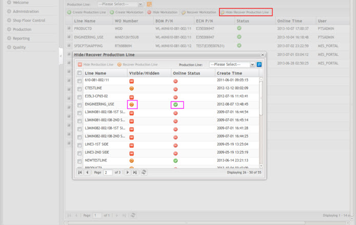
Hide/Recover Production Line
If you need to hide the obsolete PTS Production Lines, then you can do that by yourself as following steps. Otherwise, the MES Support team will be able to help you out if you need to do something at the database level.
Figure 6: Hide/Recover Production Line
1. Select Hide/Recover Production line.
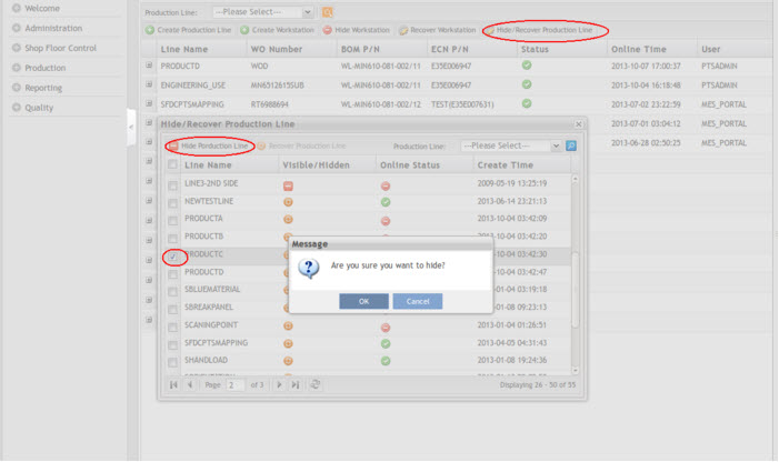
Figure 7: Hide a Production Line
2. Select a production line (The line is in offline and visible status) then select Hide Production Line.
3. Select OK to hide the production line or Cancel to exit.
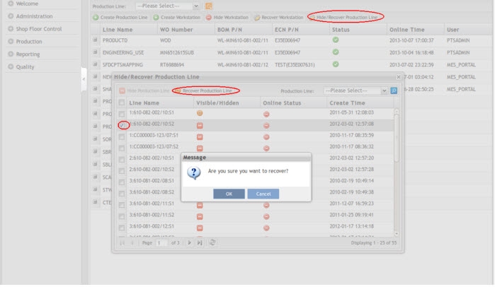
Figure 8: Recover a Production Line
4. Select a production line (The line is in offline and hidden status) then select Recover Production Line.
5. Select OK to recover the production line or Cancel to exit.
Note: The online production line is not allowed to be hidden. Please set the production line to "off-line" before hiding it.
Workstation
Create a New Workstation
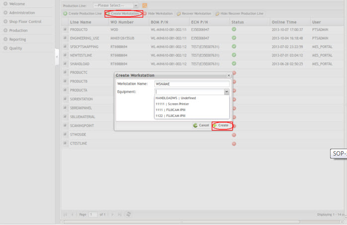
1. Select Create Workstation from the functional options menu. (See the following section for naming format suggestions).
2. Workstation Name: Enter the workstation name.
3. Select the Equipment. (This is optional)
4. Select Create to create the new workstation.
Figure 9: Workstation Name and Equipment
'Note: 'The equipment should be added first in Production > 'SMT Machine part Traceability > Machine Registry module. The suggested naming format for Workstation By Shop Floor Location
Format: Area Location + Production Zone - Placement Machine Example: F2-CP6B Explanation: Fuji CP6B placement machine located on 2nd Floor.
By Production Process
Format: Production Process + Line/Zone - Placement Machine Example: S2-CP6A Explanation: Fuji CP6A placement machine located at SMT Line 2.
By Placement machine model with associated serial number
Format: Placement machine model – Placement machine serial number
Example: CP6-SN12345
Explanation: Fuji CP6 placement machine with its own unique machine serial number SN12345.
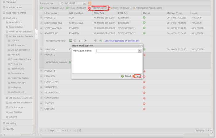
Hide WorkStation
Figure 10: Hide Workstation
1. Select Hide WorkStation.
2. Select a WorkStation (The Workstation should be at visible status)
3. Select Send to hide the WorkStation or Cancel to exit.
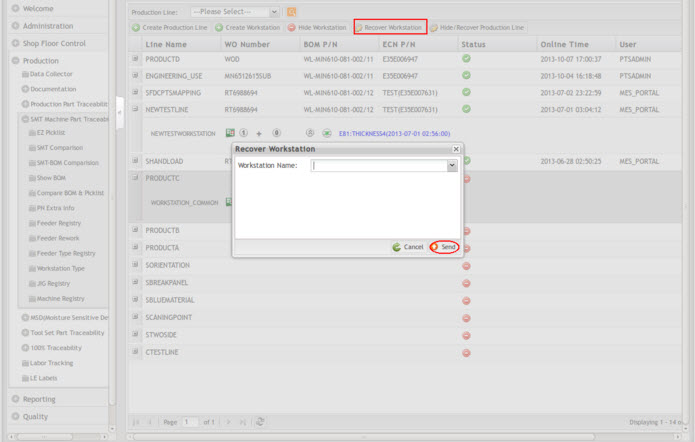
Recover WorkStation
Figure 11: Recover Work Station
1. Select Recover WorkStation.
2. Select a WorkStation (The Workstation is at hidden status).
3. Select Send to recover the WorkStation or Cancel to exit.
Add WorkStation
This module allows the user to add or remove workstation(s) from the production line.
Adding Workstation into a Production Line
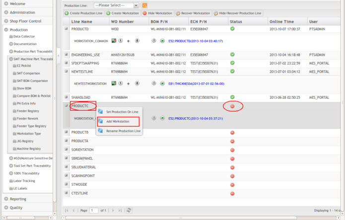
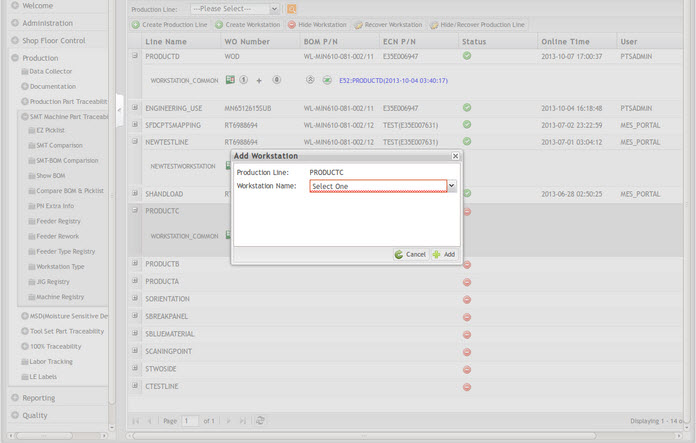
Figure 12: Add Workstation into a Production Line
1. Select the production line from the production Line list.
2. Open the pop-up menu by right-clicking on the line name then select Add Workstation menu. Select the workstation name from the Workstation name pull-down list to add to the specific production line.
3. Select Add to add the workstation.
Figure 13: Add Workstation- Set Button
Note: The selected production line must be off-line for workstation addition or removal.
Note: The Workstation Name will be auto-completed after entering the first 4 characters.
Removing Workstation from a Production Line
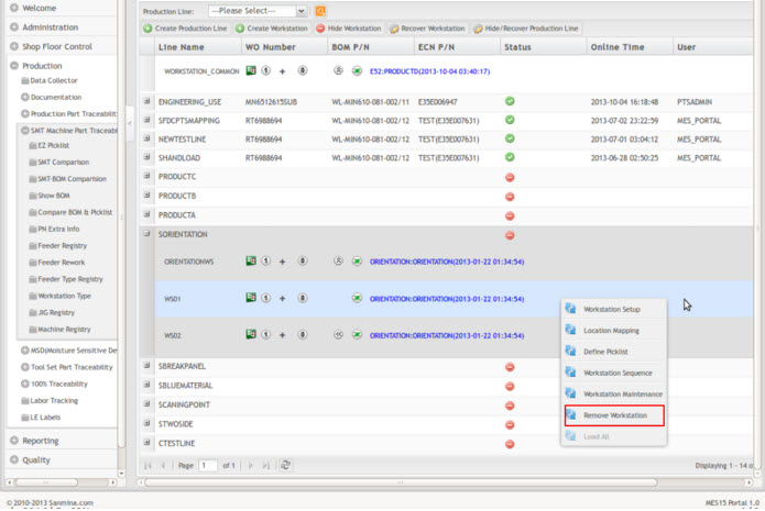
Figure 14: Remove Workstation
1. Select the production line from the production Line list menu.
2. Select the workstation name from the Workstation pull-down list which is under "In Use."
3. Open the pop-up menu by right-clicking on the workstation then select the Remove Workstation menu.
4. Select OK to remove the Workstation from this production line or select Cancel to exit.
Workstation Maintenance
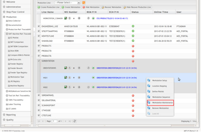
Figure 15: Workstation Maintenance
1. Select the production line from the production line list.
2. Select the workstation from the workstation(s) list.
3. Open the pop-up menu by right-clicking then select the Workstation Maintenance option.
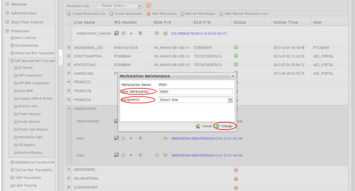
4. Renaming: Fill in a new workstation name in the New Workstation field and then select Change to rename the selected workstation name.
5. Equipment: Select the Equipment, then select Change to reset the Workstation type.
Figure 16: Workstation Maintenance- Detail
Note: The workstation can be renamed only when the production line is in "off-line" mode.
(See Set Production Off-Line)
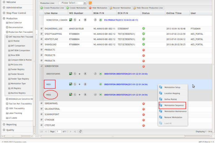
Workstation Sequence
The purpose of this module is to redefine the proper workstation sequence for the production line if the previous setup is incorrect.
Following is the example to redefine the workstation sequence:
Figure 17: Workstation Sequence in a Production Line- Before
1. Select the production line from the production Line list.
2. Select the workstation from the workstation(s) list.
3. Select Workstation Sequence to shift up the Workstation process sequence.
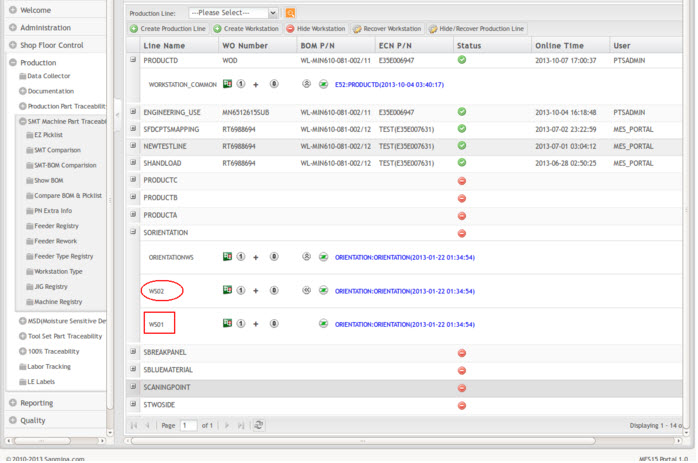
Figure 18: Workstation Sequence in a Production Line- After
Note: The workstation process sequence goes from down to up and is allowed under the Workstation Sequence option. Please move each workstation to the correct workstation process sequence if required.
Workstation Setup
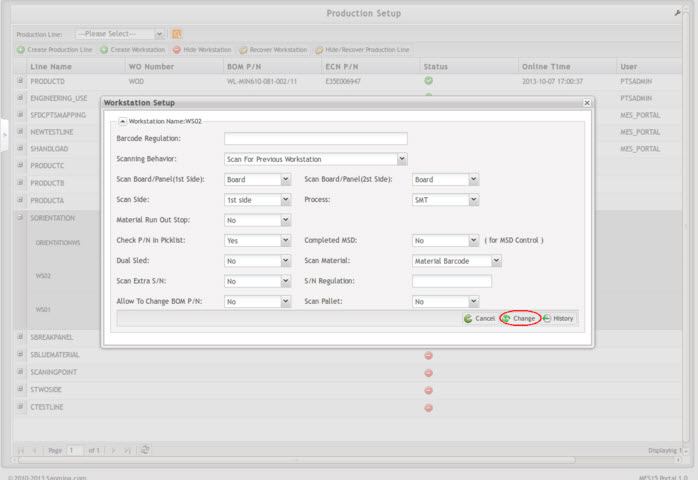
This module allows the user to set up the scanning behavior and scanning rules for each defined Workstation under the associated Production Line.
Figure 19: Workstation Set-Up Parameters
1. Select the production line from the production Line list.
2. Select the workstation to be set up, then right-click to open the pop-up menu.
3. Select Workstation Setup.
Workstation Setup Parameters
1. Barcode Regulation: (Recommended)
Fill in "Barcode Regulation" based on the serial number mask which is applied on each PCB serial number barcode label. If blank, no serial number will be validated for all PCB serial scanning.
For example: The plant set the Barcode Regulation: ^JZ[0-9]{6}$. Then the barcode can be JZ057867,JZ057868. {6} means the numbers of the characters.[0-9] means the characters can be numbers from 0 to 9.
2. Scanning Behavior: (Compulsory)
- Scan by Later Workstation: All workstation material placements can be recorded with the next Workstation(s).
- Must Scan At this Workstation: All workstation material placements are required to be recorded at this Workstation before reach and/or scan at the next Workstation(s).
- Scan for Previous Workstation: All these workstation material placements will be recorded with the previous Workstation placements.
3. Scan Board/Panel: (Compulsory)
Select the Scan Board/Panel for both 1st Side and 2nd Side
- Board: Each individual PCB board number.
- Panel: Each PCB panel number.
- Serial: Each PCB serial number.
4. Scan Extra S/N: (Compulsory)
Define if extra serial needs to be scanned. If it is required to scan the PCB board's additional barcodes such as the package label, select Yes. Default is No.
5. S/N Regulation: (Required if Scan Extra S/N is Yes)
Define the serial number barcode regulation.
6. Completed MSD: (Required if MSD control is needed)
Default is No.
Note: MSD control is only applied to the workstation(s) prior reflowing process.
7. Scan Side: (Required if Scan board/Panel is "Yes")
Define which production side(s) need to be scanned.
- 1st Side: First PCB production side or One PCB production side.
I.e. Such as PCB ’ s TOP side production only which does only have material placements on one PCB side.
- 2nd Side: Second PCB production side.
I.e. Such as the TOP side can be called the 2nd Side as it is the second production side after the BOTTOM side placement finished.
- 1st& 2nd Side: Top and Bottom side.
I.e. Both production sides are required to be scanned at the same Workstation.
8. Scan Material: (Compulsory)
- Select Material Barcode (For plants which used PTS format material label that included a unique printed PTS material barcode).
- Select SSCI P/N (For plant which might be used standard plant approved/developed material label that included printed SSCI Part Number barcode).
- Select Manufacturer P/N (For a plant that might use the manufacturer-provided label that included printed manufacturer Part Number barcode)
9. Process: (Compulsory)
Select the type of process for this workstation:
a. SMT: For SMT Machine workstation.
b. Hand Load: For Manual process workstation.
c. AI: For Auto Insertion workstation.
Note: Different setup option defines different material loading process. Refer to the Load Material work instruction for more detail.
10. Device ID: (Optional)
Enter any integer from 0 to 999 according to the SFDC setup. If the generic attribute is set for higher device numbers using the base 34 system, the device ID may go from 0 to ZZZ.
11. Select Change to set up this workstation.
12. Select History to check the log for the change of setup parameters.
Define Pick List
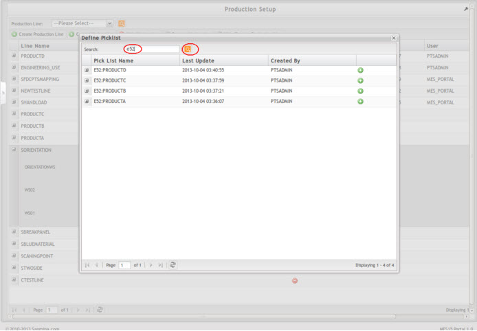
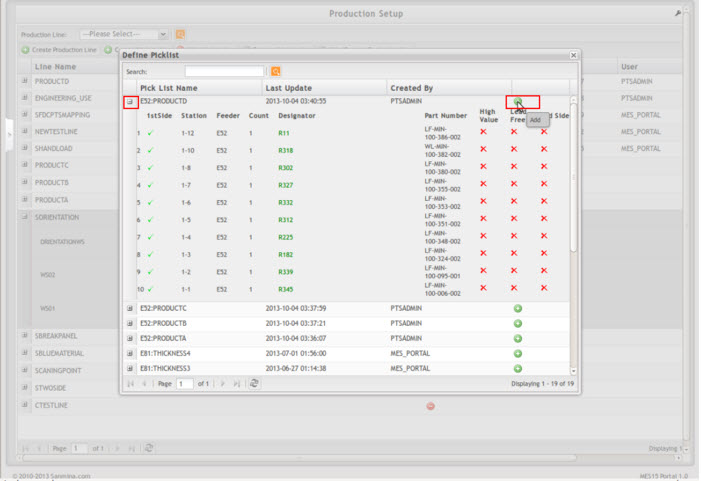
This module allows the user to assign the early prepared/loaded SMT placement program into a Workstation under the specific Production Line.
Figure 20: Select Picklist for Workstation
1. Select the production line from the production Line list.
2. Select the workstation, then right-click to open the pop-up menu.
3. Select Define Picklist.
4. Enter the keywords for the Picklist name.
5. Select Search to search Picklist name.
6. Select the Picklist name to view material placements with reference designator listing.
Figure 21: Show Picklist Option
7. Select " + " to assign the selected picklist to the Workstation. Note: For additional Picklist information, see the SMT Part Traceability work instruction.
Location mapping
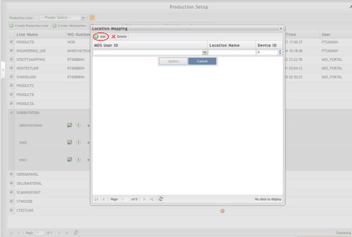
This sub-module is designed to map the PTS workstation with the SFDC location so that SFDC will forward serial number information to the pre-mapped PTS workstation upon board scanning, which helps to avoid duplicate board scanning and improve production efficiency.
To map a PTS workstation with an SFDC location, please select the workstation of a production line, and right-click to open the pop-up menu then click on Location Mapping.
Figure 22: Location Mapping Interface
1. To update an existing mapping, double click on existing mapping; edit the information, then select Update.
2. To delete the existing mapping, select Delete.
3. To configure a new mapping, select Add, and a new line will be created.
- MES User ID (Mandatory): SFDC user ID at MES. Select from the drop-down list.
- Location Name (Mandatory): Fill in the SFDC location name that to be mapped with the selected PTS workstation.
- Device ID (Optional): Fill in SFDC Device ID.
- Select Update to complete the mapping or Cancel to exit.
Set Production On/Off-Line
Set Production On-Line
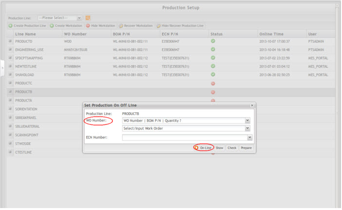
- Once the user has the production line and workstation ready, the production line must be set to" On-Line" mode to start work order production. The user cannot load material or scan board if the production line is off.
Figure 23: Work Order Selection When Set Production On-Line
1. Select the production line to be set online from the production Line list.
2. Open the pop-up menu by right-clicking, and then select Set Production online.
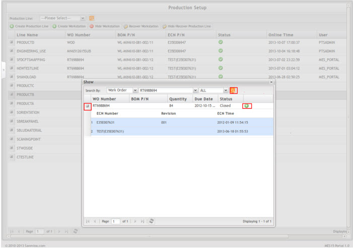
3. Enter a released Work Order number, if known, or Select the work order from the list by selecting Show.
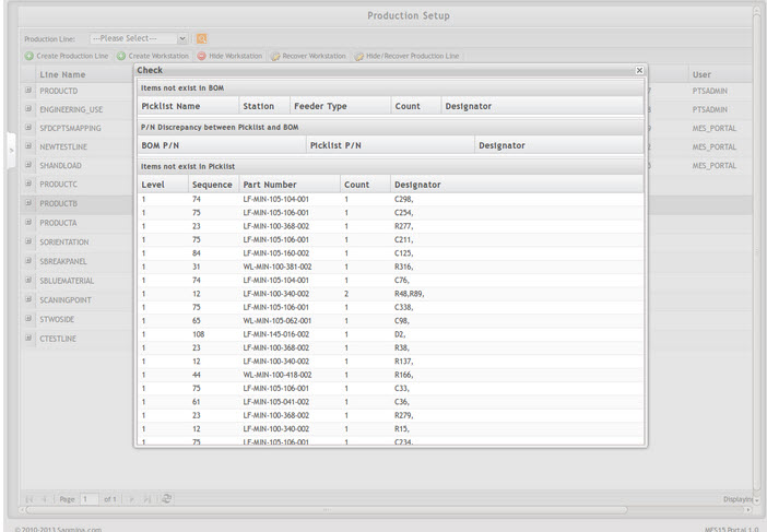
4. Select the Work Order (you can view the BOM detail by selecting the " + " at the left). 5. Select the " + " at the right to select the Work order. 6. Select Check in the BOM/PL column to verify the BOM against the defined picklist and vice versa, below two sessions, if there are unmatched items.
Figure 24: Select Work Order
Figure 25: Show BOM/PL Validation
- Items that do not exist in BOM
To compare and validate all material placements in the SMT placement program (i.e. PickList) that do not exist in ERP BOM.
- Items that do not exist in PickList
To compare and validate all material placements in ERP BOM that do not exist in the SMT placement program (i.e. PickList).
7. Fill in the required Work Order with associated production ECN.
8. Select On-line to set the production line online after confirming the Work Order and ECN selection.
Note: If the work order BOM components do not match the defined picklist, the user will need to follow confirmation and update accordingly.
- Confirm that the Work Order you enter/select is associated with the latest ECN.
- Confirm the Picklist defined is correct.
Set Production Off-Line
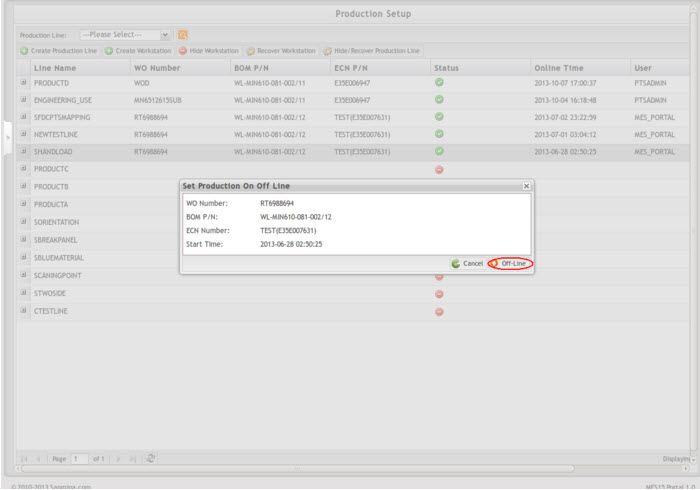
Once the work order is completed on the production line, the production line needs to be set to Off-Line mode.
1. Select the production line to be set online from the production Line list.
2. Open the pop-up menu by right-clicking then select Set Production offline.
3. Choose Set Production On/Off-Line functional module.
4. Select Off-Line to set the line offline.
Figure 26: Setup Production Offline
Load All
This module allows the user to load all materials to the workstation under the following conditions.
1. Set the production line offline (do not unload materials).
2. Change the setting for the workstation if needed.
3. Set the production line to online again.
4. The user can use the "Load All" function to load all materials to the workstation.
Note: The user can only load all when not using the unload function.
Note: If some materials are invalid/expired, those materials will fail to load if using the "load all" function. All other valid materials will load successfully.
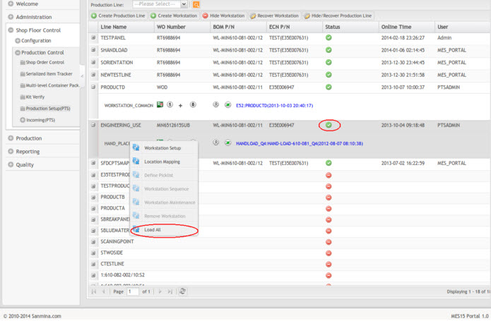
Figure 27: Load All
1. Set the production line online from the Production Line list.
2. Open the workstation lists by selecting the " + " at the left. 3. Open the pop-up menu by right-clicking on the workstation, and then select Load All.
4. The information will display if the Load All function succeeds.
5. The user can check the loaded material on the page "Load Material Report."
