Difference between revisions of "How to integrate Conduit-PTS Scanning"
Helena wang (talk | contribs) |
Helena wang (talk | contribs) |
||
| Line 344: | Line 344: | ||
| − | |||
| − | {| border="1" cellpadding="1" cellspacing="1" style="width: 500px;" | + | = <span class="mw-headline" id="Document_Revision_History"><span class="mw-headline" id="Document_Revision_History"><span class="mw-headline" id="Document_Revision_History"><span class="mw-headline" id="Document_Revision_History"><span class="mw-headline" id="Document_Revision_History"><span class="mw-headline" id="Document_Revision_History">Document Revision History</span></span></span></span></span></span> = |
| + | |||
| + | {| border="1" cellpadding="1" cellspacing="1" class="wikitable" style="width: 500px;" | ||
|- | |- | ||
! scope="col" | Date | ! scope="col" | Date | ||
| Line 353: | Line 354: | ||
! scope="col" | Version | ! scope="col" | Version | ||
! scope="col" | Change Reference | ! scope="col" | Change Reference | ||
| − | ! scope="col" | | + | ! scope="col" | Approved By |
|- | |- | ||
| 11/04/2020 | | 11/04/2020 | ||
Revision as of 09:02, 11 November 2020
Conduit-PTS Scanning Integration
Contents
Introduction
This guide shows you how to configure and activate Conduit-PTS functions.
Conduit Admin and PTS Admin are required to complete the configuration on both systems.
Required to verify (upgrade if needed) the correct version before implementing Conduit-PTS Integration.
Configuration
To activate the function, setup needs to be done in Shop Floor ID and PTS.
Shop Floor Configuration
- Click the Data Editor under the Shop Floor Control -> Configuration -> Shop Floor Configuration menu.
Figure 1: Data Editor Menu
- Select one Shop Floor ID, then click the Edit button.
Figure 2: Select Shop Floor
- Add this below line into the setup data editor.
OPTIONS URL_WEB_SERVICE NAME=PTS VALUE=<a href="http://pts-uat.sanmina.com:8080/pts">http://pts-uat.sanmina.com:8080/pts</a>
Figure 3: Data Editor Options Example
#Conduit -PTS Service (For example)
OPTIONS URL_WEB_SERVICE NAME=PTS VALUE=http://pts-uat.sanmina.com:8080/pts
Note: Please replace http://pts-uat.sanmina.com:8080/pts with your Conduit-PTS service URL.
Save the changes before exit.
Server information Configuration
Make sure you have Conduit_shopFloorID & Conduit program configured from Administration-->Server information
- Click Server information under the Administration menu
- Add the Server information for the Conduit_ShopFloorID and Conduit program.
Figure 4: Add Server Information
Figure 5: Server Information List
PTS Configuration
There are 2 places that need to set up in PTS portlets
- Add MDS Net User in PTS Administrator(System setting)
- Location Mapping in Workstation Setup(PTS)
Add MDS Net User
Raise P3 Service Request to the MES Support team to request add MDS Net User in Traceability Administrator ->System setting.
Please include the below details in your TT
For Example:
Plant Name: E83 Penang
MES Portal Server:143.116.xxx.xxx
NetUser ID: P21dc1,p21dc2,p21dc3
Support team to add the MDS Net User refer to the picture as follows.
Note: The MDS Net Users separated by commas.
Workstation Setup (PTS )
- Login to MES15 and from the pull-down menu(Shop Floor Control->Production Control->Traceability Setup.
- Select “Production Line” and “Workstation”
- Right, Click on “Workstation” to show the right menu then click on “Location Mapping” as below screenshot.
Figure 6: MDS Net User
Figure 7: Location Mapping Menu
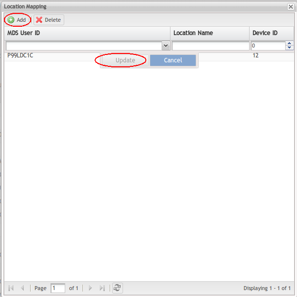
Location mapping page prompt up.
Click theAdd button to add a mapping.
- MDS User ID (Compulsory)
Figure 8: Location Mapping
- This is referring to MDS Net User(Defined at system setting).
- All MDS NetUser ID added in system settings will appear in the pull-down menu.
- Select the correct SFDC NetUser ID.
- Location Name (Compulsory)
- Location name created in jMDS Location Maintenance (example S002 SMT Insp Bot or A002
SMT Insp Top or SMTT SMT Top)
- Value must be the first 4 characters from the location name (S002, A002, or SMTT)
- Device ID
- Device ID that associate to location name in Data Collector Maintenance
-
- - Example 1 or 401 or 508
Clickthe Update button to save the configuration in PTS for the selected production line and workstation.
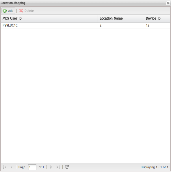
Once the mapping save in PTS, a list of location mapping show below
Figure 9: Location Mapping Example
Turn on the production line as usual and Conduit-PTS ready for action.
Conduit-Scanning Operation
By using NetDC or emulator, users can scan serial numbers and update to both Conduit and PTS.
Conduit Commands
- ScanPtsBoard
- CheckPtsComponent
- ptssplitpanel
- UpdatePtsComponent
- Validateboard
- LoadPtsMaterial
Scan Scenario
Conduit-PTS call
Macro: LoadPtsMaterialMacro
Load the material to the slot
Figure 10: Load Material to Slot
Figure 11: Load the Material Successfully
Tried to load the same material to the slot.
Conduit Macro: CheckPtsComponentMacro
Verified the material has been loaded
Note:
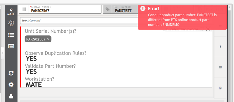
Before scanning, we need to make sure the location mapping to the workstation, otherwise we will have the following error.
Figure 14: Location not Mapping
Macro: ScanPtsBoardMacro
After loading the material and we are able to scan the serial number
Scanned serial: PAKS02567, PAKS02568, PAKS02569
Figure 15: Scan PTS Board
Material runs out:
Figure 16: Check Material Runout
Loaded the material After a material runout
Figure 17: Load More Material when Runout
Macro: UpdatePtsComponentMacro
Material splicing to the slot
Figure 18: Material Splicing to Slot
Conduit macro: validate board
Figure 19: Validate Board
Reporting
PTS scan board in production
Figure 20: PTS scan board in production
Board history report
Figure 21: Board History Report
Material onboard report:
Figure 22: Material on Board Report
Further assistance
For further assistance on Conduit-PTS Integration, please do not hesitate to contact the MES Support team.
Document Revision History
| Date | Author | Title | Version | Change Reference | Approved By |
|---|---|---|---|---|---|
| 11/04/2020 | Helena Wang | Technical Writer | A | The first version. | |
| 11/05/2020 | Marisol Vargas | Technical Writer | A1 | Peer Review, structure, and grammar | Simon Zhou |


