Difference between revisions of "SOP-42Q-MES0049 SMT Part Traceability"
| Line 277: | Line 277: | ||
<br> '''Figure 9: Workstation Type''' | <br> '''Figure 9: Workstation Type''' | ||
| − | [[Image: | + | [[Image:Final Work Station Image.jpg]]<br> |
2. Select '''Add Workstation Type'''. Thiswill add a new line in the list. | 2. Select '''Add Workstation Type'''. Thiswill add a new line in the list. | ||
| Line 283: | Line 283: | ||
<br> '''Figure 10: Add Workstation Type''' | <br> '''Figure 10: Add Workstation Type''' | ||
| − | '''[[Image: | + | '''[[Image:SOP-5-I-MES0048-C_RA1_Add_Workstation_Type.jpg]]''' |
3. Enter the '''Workstation Type Name''', '''Max Station''', and '''Max Table''', and then select '''Update '''to add a new workstation type'''.''' | 3. Enter the '''Workstation Type Name''', '''Max Station''', and '''Max Table''', and then select '''Update '''to add a new workstation type'''.''' | ||
| Line 293: | Line 293: | ||
<br> '''Figure 11: Delete Workstation Type''' | <br> '''Figure 11: Delete Workstation Type''' | ||
| − | [[Image: | + | '''[[Image:SOP-5-I-MES0048-C_RA1_Delete_Workstation_Type.jpg]]''' |
| − | + | <br> | |
=== Show BOM === | === Show BOM === | ||
| Line 305: | Line 305: | ||
<br> '''Figure 12: Show BOM''' | <br> '''Figure 12: Show BOM''' | ||
| − | [[Image: | + | '''[[Image:SOP-5-I-MES0048-C_RA1_Show_BOM.jpg]]''' |
| + | |||
| − | |||
All BOM P/N (ECN) in the system will list out in pages. The user can search a BOM by '''BOM P/N''' or '''BOM ECN''', and/or by '''Active''' or '''Disabled'''. | All BOM P/N (ECN) in the system will list out in pages. The user can search a BOM by '''BOM P/N''' or '''BOM ECN''', and/or by '''Active''' or '''Disabled'''. | ||
| Line 323: | Line 323: | ||
<br> '''Figure 13: Disable BOM''' | <br> '''Figure 13: Disable BOM''' | ||
| − | [[Image: | + | '''[[Image:SOP-5-I-MES0048-C_RA1_Disable_BOM.jpg]]''' |
<br> | <br> | ||
| Line 336: | Line 336: | ||
<br> '''Figure 14: Show BOM''' | <br> '''Figure 14: Show BOM''' | ||
| + | |||
| + | '''[[Image:SOP-5-I-MES0048-C_RA1_Show_BOM.jpg]]''' | ||
| + | |||
| + | [[Image:SOP-5-I-MES0048-C_RA1_Show_BOM.jpg]] | ||
[[Image:14 SMT show bom -show bom.png|700px|14 SMT show bom -show bom.png]] | [[Image:14 SMT show bom -show bom.png|700px|14 SMT show bom -show bom.png]] | ||
Revision as of 17:20, 13 December 2016
Cirrus > Production > SMT Part Traceability
This edition applies to MES15 Portal 1.0 Application and all subsequent releases and modifications until otherwise indicated in new revisions.
Contents
Production
The Parts Traceability System (PTS) is one of the applications within the MES suite of tools. It was developed to meet the demands of customers to provide component level traceability as well as quality controls. This system plays a very important role in automating the production lines and raising productivity as well as enforcing rigorous product quality control. It has been implemented to many plants across the globe. This application and the features it provides continue to evolve, as the changing technologies used for the SMT process equipment tools become more detailed and rich in functionality.
SMT Machine Part Traceability
General Notes
1. This Work Instruction is a basic general training guide and is not meant to teach the process flow for individual plant or department functionality. Individual 42Q sites may have minor or specific process changes that will be documented at the site level.
2. Online help is available in PTS.
Pre-Requisites
1. Completed SOP-5-I-PTS0001-C Basic Navigation.
2. Read SOP-5-I-PST0000-C_RA_PTS GLOSSARY
3. Java Runtime Environment 1.5 or above installed.
4. Microsoft Excel 2000 or above installed.
Overview
EZ-Picklist is a web-based interface to collect and manipulate SMT placement programs into PTS for material verification against the BOM. It is compatible with different brands of SMT machine models as listed follow. Please consult with PTS Regional Support for full listing of machine type and compatible models.
| Machine Type | Model | Software Name & Version | File Name Extension |
| Universal | GSM | UPS+2.5.2 | ci2 |
| Universal | HSP4796 | UCT-53 | ncz |
| Universal | HSP4797 | UCT-53 | pca |
| Panasonic | CM402 | PT200 | txt |
| Panasonic | DT401 | PT200 | txt |
| Fuji | CP643 | Unicam 6.2 | pgo/db |
| Fuji | CP642 | Unicam 6.2 | pgo/db |
| Fuji | FCP6 | Unicam 6.2 | pgo/db |
| Fuji | FIP2 | Unicam 6.2 | pgo/db |
| Fuji | FIP3 | Unicam 6.2 | pgo/db |
| Fuji | QP242 | Unicam 6.2 | pgo/db |
| Fuji | QP341/QP351 | Unicam 6.2 | pgo/db |
| Fuji | NP133/NP153 | Unicam 6.2 | pgo/db |
| Fuji | CP643 | FujiFlexa2.4.0.7 | pgo/xml |
| Fuji | CP642 | FujiFlexa2.4.0.7 | pgo/xml |
| Fuji | FCP6 | FujiFlexa2.4.0.7 | pgo/xml |
| Fuji | FIP2 | FujiFlexa2.4.0.7 | pgo/xml |
| Fuji | FIP3 | FujiFlexa2.4.0.7 | pgo/xml |
| Fuji | QP242 | FujiFlexa2.4.0.7 | pgo/xml |
| Fuji | QP341/QP351 | FujiFlexa2.4.0.7 | pgo/xml |
| Fuji | NP133/NP153 | FujiFlexa2.4.0.7 | pgo/xml |
EZ Picklist
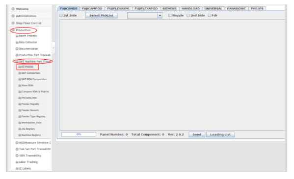
1. To access the EZ Picklist page, navigate to Production > SMT Machine Part Traceability > EZ Picklist.
Convert SMT Program to Picklist
Figure 1: EZ Picklist
Select SMT Program File
Figure 2: Select Picklist
1. Click Select Picklist to locate the desired material placement file.
2. Select the SMT program file name. Please refer to SMT job profile prepared by SMT Engineer for the file name for each SMT machine.
3. Select Open. Details of the picklist will display.
Figure 3: Picklist Details Window
All 42Q P/N, Station, Feeder, Count, and Designator are encoded in SMT placement program prepared by the SMT Engineer.
- Select the 1st production side and/or 2nd production side (as per picklist setup for production environment).
- Select the High Value option and the Lead Free option checkbox associated to each individual material part number if required.
- Select Send to send the picklist to the PTS server.
- After the picklist is submitted to the server, message prompt "Complete" will display.
- Select Confirm to confirm it.
- Select Loading List to send the picklist to C:\pts\loadinglist\ (by default).
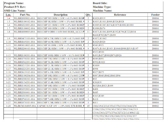
- Select Loading List to send the picklist to default path: C:\pts\loadinglist\ (Windows); /temp/loadinglist (Linux) . See figure 4
NOTE: Default path for Loading List report is customizable. Local plant can contact PTS team to do the customization.
Figure 4: Picklist Loading List
NOTE: The Surface Mount Devices (SMD) Loading List cannot be used as a control document without stamp/sign by authorized personnel defined by plant such as SMT production line supervisor/team leader. This is designed to be used for materials loading reference only.
SMT Comparison
This module is designed to compare the standard SMT program and the current SMT program, which allows the user to find the differences between the two programs leading to easier operation.
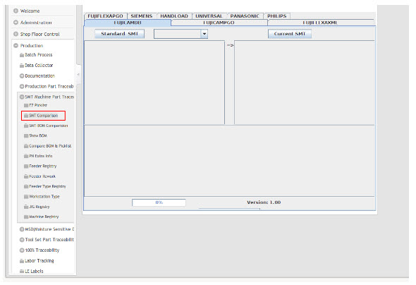
1. To access the SMT Comparison page, navigate to Production > SMT Machine Part Traceability > SMT Comparison.
Figure 5: SMT Comparison
All available SMT machines are displayed in tabs at the top of the screen. There are two grids displayed under each tab for the user to be able to compare the programs of each selected machine type.
2. Select the correct machine tab.
3. Select Standard SMT. The system will display a dialogue box prompting the user to select a file. Make sure the file selected matches the machine type.
4. Select Current SMT, and then select the current SMT program for comparison.
5. After both programs have been selected, the system will compare the two and display the differences to the user.
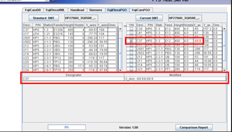
Figure 6: SMT Comparison- Difference
The modified value is marked with red in the Current SMT table. The corresponding checkbox for the item will be selected automatically.
- Designator: List of designators that have been modified.
- Modified: Displays original data and new data. (E.g. X_Axis: -69.93/-69.9, ’-69.93’ is original data, ’-69.9’ is new data.)
6. Select Comparison Report. A report will be generated under C:\pts\report to log what has been changed.
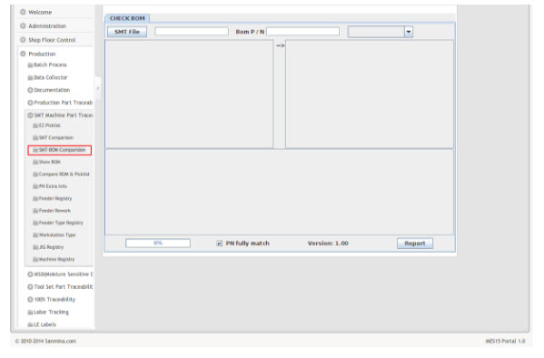
SMT-BOM Comparison
This function is used to determine if the picklist exists in a BOM file.
1. To access the SMT-BOM Comparison page, navigate to Production > SMT Machine Part Traceability > SMT-BOM Comparison.
Figure 7: SMT-BOM Comparison
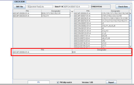
2. Select SMT File. The system will display a dialogue box prompting the user to select an appointed ezPicklist file.
3. Enter correct BOM part number into BOM P/N text box, then select Enter.
4. Select correct ECN number from pull down list.
5. Select Check BOM. If there are any errors recorded in the BOM file, an error message will display in the table below.
6. Select Report. An ezPicklist excel file will be generated and saved under the default path.
Figure 8: SMT-BOM Comparison Difference
Workstation Type
With this module the user is allowed to add/delete/change a workstation type.
1. To access the Workstation Type page, navigate to Production > SMT Machine Part Traceability > Workstation Type.
Figure 9: Workstation Type
File:Final Work Station Image.jpg
2. Select Add Workstation Type. Thiswill add a new line in the list.
Figure 10: Add Workstation Type
3. Enter the Workstation Type Name, Max Station, and Max Table, and then select Update to add a new workstation type.
4. Double click on the existing Workstation Type Name. The information will display and is available to edit. Change the desired information, and then select Update to change a workstation type.
5. Click the red cross on the right to confirm the deletion of a workstation type.
Figure 11: Delete Workstation Type
Show BOM
This module allows the user to view BOM, disable BOM or enable BOM.
1. To access the Show BOM page, navigate to Production > SMT Machine Part Traceability > Show BOM.
Figure 12: Show BOM
All BOM P/N (ECN) in the system will list out in pages. The user can search a BOM by BOM P/N or BOM ECN, and/or by Active or Disabled.
2. When the user selects the left checkbox to select an item, Enable, Disable, and Show will become available.
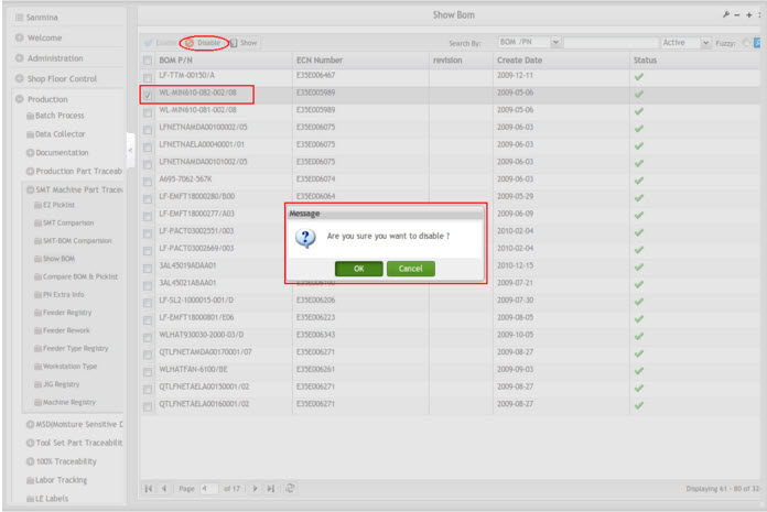
Enable/Disable BOM
1. Search the BOM by Enable/Disable and select Go. All Enabled/Disabled BOM will be displayed.
2. Select the left Checkbox on target BOM and then select the button Disable/Enable.
Figure 13: Disable BOM
Show BOM
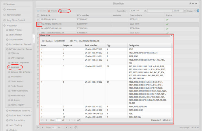
This function allows the user to view all existing items under the selected BOM.
1. Search the BOM.
2. Select the left checkbox on the target BOM and then select Show.
Figure 14: Show BOM
Compare BOM and Picklist
This module is designed to verify that the designators in the BOM are consistent with the ones in the SMT program. It also lists the differences between the two.
1. To access the Compare BOM and Picklist page, navigate to Production > SMT Machine Part Traceability > Compare BOM and Picklist.
Figure 15: Compare BOM and Picklist
Search by Line Name
1. Enter the Line Name.
2. Enter the BOM number into the BOM textbox.
3. Select the correct BOM ECN from the BOM ECN drop-down list.
4. Select Search. The results will be shown on the right.
5. If BOM does not match the Picklist, the following screen will display. (See Figure 16)
Figure 16: Compare by Line- No Match
Search By Picklist Name
1. Select or enter the Picklist Name.
2. Enter the BOM number in the BOM textbox.
3. Select a correct BOM ECN from the drop-down list.
4. Select Search. The result shown on the right will be slightly different with this option checked or unchecked. (See figure 17).
Figure 17: Compare by Picklist Name- No Match
P/N Extra Info
This module allows the user to flag the high value material and define whether or not to track and show an orientation picture for a particular material during the process of material loading.
1. To access the P/N Extra Info page, navigate to Production > SMT Machine Part Traceability > P/N Extra Info.
Figure 18: P/N Extra Info
2. The user can perform a search by entering the target part number and/or defining parameters, such as Orientation, Track, and High Value.
3. The user can change the information by selecting an item and double clicking on its part number (see figure 19).
Figure 19: P/N Extra Info- Update

- Part Number: The part number selected by user. Display only.
- Description: Description of the item selected by user. Display only.
- Orientation: Whether or not to show the orientation picture when loading this material. select Yes or No.(Note: This option will be disabled only when " Show Orientation Picture=Yes" under System Setting page.
- Track: Whether or not to track the material. Select Yes or No.
- High Value: Define whether or not the selected item is a high value item. Select Yes or No.(Note: This option will be disabled only when "High Value Mark=Yes" under System Setting page.
- High Value: Define whether or not to control the MPN information when jointing this material in the material queue function.. Select Yes or No.
- Lot code Control: Define whether or not to control the lot code information when jointing this material in the material queue function. Select Yes or No.
- Traceability level: Define the traceability level. Select Single Scan or Scan Point or 100% traceability.
- Update: Select this button to save the configuration.
- Cancel: Select this button to go back to previous window without saving.
Feeder Type Registry
This module is used to add or maintain the feeder type. The following instructions introduce the user to a sample to teach how to operate the function.
1. To access the Feeder Type Registry page, navigate to Production > SMT Machine Part Traceability > Feeder Type Registry.
Figure 20: Feeder Type Registry
Add Feeder Type
This section will instruct the user on how feeder type can be added.
1. Select Add feeder Type. A new line will be added.
Figure 21: Add Feeder Type
- Select the Machine Type Name.
- Enter the Feeder Type name
- Select Update. The feeder type will be created.
NOTE: A warning message "This feeder type:(TEST) has already existed!" will display if the feeder name already exists. A feeder type must be matched with SMT program.
Search Feeder Type
1. Enter the Feeder Type in the search box, and then select GO.
2. The related feeder type will be displayed.
Feeder Type Maintenance
This section will instruct the user on how to maintenance an existing feeder type.
Figure 22: Feeder Type Maintenance
1. Double click on the feeder type under the Feeder Type column.
2. Enter the feeder regulation which applies to the associated feeder type.
3. Enter the feeder maximum usage into the Max Usage field and the maintenance period into Maint Period field.
4. Enter the minimum usage times into Minimum Alarm Usage. When the usage times are the same as the defined minimum usage times, the feeder name will be marked with yellow at the load material module.
5. Enter the minimum usage days into Minimum Alarm Maintenance Period. When the usage days are equal to the defined minimum usage days, the feeder name will be marked with yellow at the Load Material module.
6. Select Update to update all associated feeder type records.
7. By selecting History, the user can review the change information for this feeder type.
Feeder Registry
This section is going to introduces:
- How to add feeder record
- How to lookup the feeder maintenance record
- How to maintain a feeder name
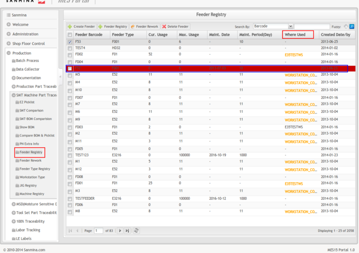
1. To access the Feeder Registry page, navigate to Production > SMT Machine Part Traceability > Feeder Registry.
Figure 23: Feeder Registry
2. All feeder information will display.
3. Expired feeder rows will be highlighted in red.
Create feeder
1. Select Create Feeder. A new sub-page will display.
Figure 24: Create New Feeder
2. Enter/Select the Feeder Type.
3. Enter the Feeder Barcode.
4. Enter the number of feeders to be generated using the new provided feeder barcode. The default value is 1.
For example:
Select Feeder Type: BFE-32+
Input Feeder Barcode: 10001
Number of Feeder: 3
I.e. Three sequence order feeder records will be create (10001, 10002, and 10003)
5. Select Create.
Change Feeder/Feeder Registry
1. Select a feeder by checking the box to the left of the Feeder Barcode.
2. Select Feeder Registry.
Figure 25: Feeder Registry
5. Enter the Feeder name if needed.
6. To set maintenance date automatically, select AUTO.
7. To disable feeder maintenance, select Unlimit.
8. Enter a specific maintenance date.
9. Select the Change the button to update feeder name and maintenance date.
10. Select the Cancel button to return to feeder registry report page.
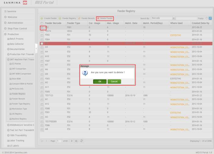
Delete feeder
1. Select a feeder by checking the box to the left of the Feeder Barcode.
2. Select Delete Feeder.
Figure 26: Delete Feeder
3. Select OK to confirm the deletion of the selected feeder.
Feeder Rework
It is very important to maintain feeders as schedule or usage due to the fact that every feeder has a particular lifespan. PTSWEB provides two options for scheduling purposes; Maximum Usage Times and Maintenance Periods.
1. Select a feeder by checking the box to the left of the Feeder Barcode.
2. Select Feeder Rework.
Figure 27: Feeder Registry- Feeder Rework
Figure 28: Feeder Rework- Main
3. Enter feeder name.
4. Change the Maximum Usage and Maintenance Period as defined in the feeder registry schedule ruled by SMT engineers.
5. Change the Min alarm Usage and Min alarm Maintenance Period.
6. Service Description: Select service description from the drop down list. The description log can be added when the user reworks or maintains the function.
7. The user can select Add to add the new service description.
8. Select Send to update the system.
NOTE: An "in-use" feeder cannot edited/deleted/reworked.
JIG Registry
Prerequisites
- Set production offline.
- This function only works on request.
- Please set "Jig Control = Yes" in System Setting page before using this function.
Overview
- This function which supports tooling has been installed in the SMT machine correctly and is for a specific product.
- The following is an example, which shows the user how to operate this function:
NOTE: To begin to use the Jig function, the user needs to set the Jig in this module first.
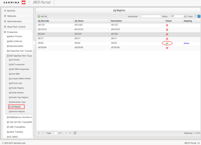
1. To access the Jig Registry page, navigate to Production > SMT Machine Part Traceability > JIG Registry.
NOTE: The enabled and disabled jigs have different colors in the status field.
Figure 29: JIG Registry
Add JIG
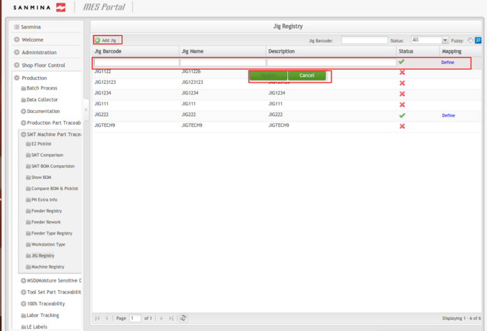
1. Select Add JIG located above the JIG Barcode list.
Figure 30: Add JIG
2. Input the JIG barcode, JIG name, and the description and select Update to add a new JIG.
NOTE: The status will be enabled by default.
Update JIG
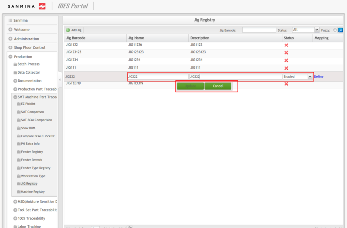
1. Double click on the jig barcode to enable editing.
Figure 31: Update JIG Information
NOTE: The jig barcode is read only.
2. Input the JIG Name, Description, and Status.
3. Select Update.
NOTE: The JIG status can change from either enabled to disabled, or disabled to enabled.
NOTE: An "In Use" JIG cannot be changed.
Define JIG mapping
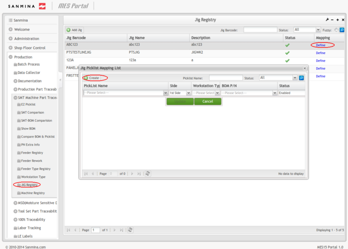
1. If the JIG barcode is in enabled status, select Define to maintenance the mapping.
2. Select Create to add a new mapping for the Jig.
Figure 32: JIG Registry- Mapping
Update JIG Mapping
1. Double-click on the existing mapping to update it.
Figure 33: Update JIG Mapping
2. Change the Picklist Name, Side, Workstation Type, BOM P/N, and Status.
3. Click the button Update to change the mapping.
4. Click the button Cancel to cancel.
Machine Registry
This module is intended to instruct users on how to manage the machines.
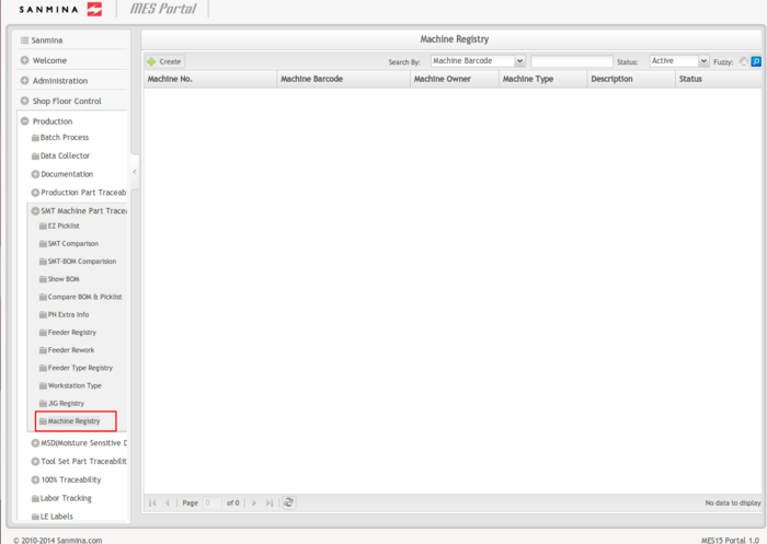
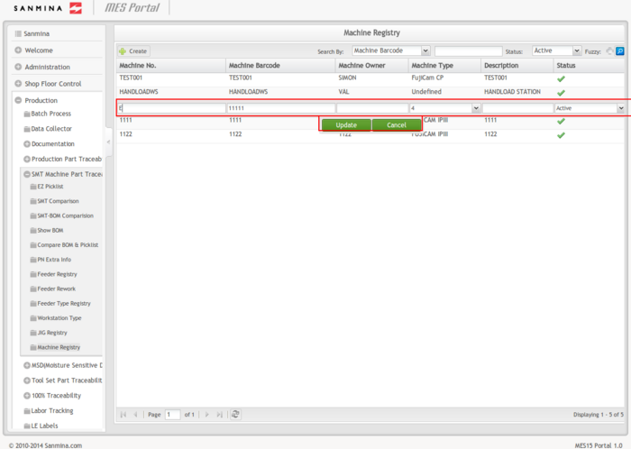
1. To access the Machine Registry page, navigate to Production > SMT Machine Part Traceability > Machine Registry.
Figure 34: Machine Registry
Create New Machine
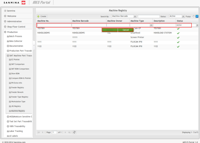
1. Select Create located above the Machine No. list to create a new line.
2. Enter the Machine No, Machine Barcode, Machine Owner, and Description, and select one Machine type, then select Update.
3. The new machine status is active by default.
Figure 35: Machine Registry- Add
Search a Machine
1. SelectMachine Barcode or Machine type in the Search By drop down box. Enter the necessary content, and select the status, then select the search ICON on the right of the main screen. The results will display in the list below.
2. Select Fuzzy. The search results will be the machines with barcode names that contain the search contents.
Update a Machine
1. Double click the line to be edited.
2. Change the appropriate information, and then select Update to update the Machine.
3. The machine status can change from either active to inactive or inactive to active.
Figure 36: Machine Registry-Update
Document Revision History
| Date | Author | Title | Version | Change Reference |
| 08/01/13 | Helena Wang | Technical Writer | 1.0 | Initial SO Work Instruction |
| 02/17/14 | Ashley Martin | Technical Writer | 1.0 | Review and Format |
| 02/28/14 | Elaine Fonaro | Technical Writer | 1.0 | Format for WIKI |
