Difference between revisions of "SOP-42Q-MES0009 Mfg Line Maintenance"
(No difference)
| |
Revision as of 19:28, 7 March 2014
This edition applies to MES15 Portal 1.0 Application and all subsequent releases and modifications until otherwise indicated in new revisions.
Contents
SFDC Configuration
The Shop Floor Data Collection System (SFDC) communicates interactively with the Customer Order Processing System (COPS), and Statistical Process Control/Statistical Quality Control (SPC/SQC). The Manufacturing Data System (MDS) makes the communication between these systems possible.
SFDC provides real-time information used by SPC/SQC and MESWeb to create quality control reports. The data configuration for SFDC PC is handled within the Manufacturing Data System (MDS), which is a complete factory automation system. The SFDC System uses barcode scanning, both manual and automated, to monitor and control a single product line or an entire plant. SFDC Configuration collects data, provides analysis, maintains unit histories, and controls product movement on the manufacturing floor.
The system provides Access Control between the modules of the application, including the portlets of each screen. The current version has an SFDC Configuration page which provides access to all sub modules pages and its functions (view, add, edit, delete, print and generate output file.
Set up SFDC Configuration
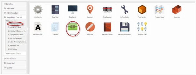
1. To access the SFDC Configuration, select SFDC Configuration in the menu. The main SFDC Configuration and sub modules page is displayed:
Figure 1: MDS Portal – SFDC Configuration Sub modules
NOTE: A user only has access to the modules assigned to his/her profile.
Mfg Line Maintenance
This portlet enables the user to assign data collector locations to a manufacturing line for use with the SOMS system.
Add Mfg Lines
This portlet enables the user to add manufacturing line configurations to the database.
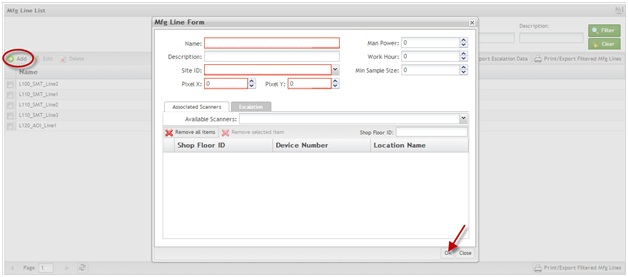
1. To add manufacturing lines, click the Add icon. The Mfg Line Form is displayed.
Figure 2: Mfg Line Form
To add or edit a manufacturing line,
1. Enter the Name and the Site ID in the respective fields. If it is a WIP Location Line, at least one location must be assigned. Otherwise, the Pixel X and the Pixel Y, and at least one scanner must be assigned.
The name must be created according the following rules:
- 2 chars for Level or Modules (areas of interests) - Ex: L1; M2
- 2 chars to group Process Lines - Ex: L110; M250
- 1 char with "_" + Process Name + 1 char with "_" - Ex: L110_SMT_; M250_PTH_
- Line name - Ex: L110_SMT_Line1; M250_PTH_Line2.
NOTE: If the manufacturing line is WIP location line, the name must end with "WIP".
NOTE: The Site ID can be changed if all Site ID references were updated in the SFDC Miscellaneous Configuration sub-module. If it is a WIP location line, it is not possible to create an escalation for this manufacturing line.
Man Power, Work Hour, Min Sample Size, fields are going to be enabled only after the user selects enters the mandatory Mfg Line Form fields.
NOTE: The Man Power and Work Hour fields will be used in the MES Web reports.
Adding Escalation E-mails:
Add Escalation e-mails by
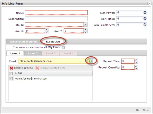
1. Entering an email address and selecting the Add icon. The escalation emails allow adding four levels of emails. Level 2, Level 3, and Level 4 tabs become available only when the information in the previous tab has an email addressed assigned to it.
Figure 3: Escalation
Using the available filters:
Scanners can be filtered by Shop Floor ID, Device Number, or Location Name using the Available Scanners field under the Associated Scanners tab:
- To filter by location, enter the Location name. (e.g., S076).
- To filter by Shop Floor ID, enter the shop floor ID (e.g., p99dcuat1).
- To filter by Device, enter the Device number (e.g., 76).
Adding or Removing scanners:
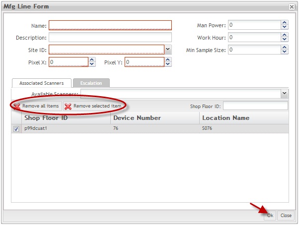
Figure 4: Add/Remove Scanners
To add a scanner,
1. Select it from Available Scanners in the drop-down list.
To remove a specific one,
1. Select the desired scanner, select Remove Selected Item.
To remove all items,
1. Select Remove All Items.
2. Select Ok to save, or Cancel to cancel the operation.
NOTE: The Location Tab allows the setup of manufacturing lines by locations, instead of scanners.
Edit Mfg Lines
This portlet enables the user to edit manufacturing line configurations. The steps for editing manufacturing lines are the same as those for adding. For further information, see the Add Mfg Line section above.
To edit manufacturing lines,
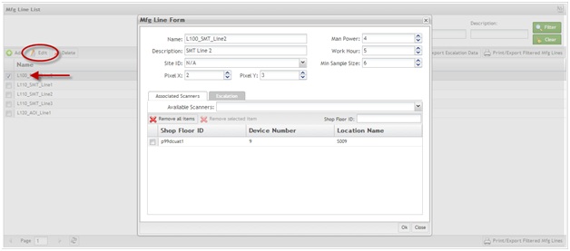
1. Select the desired line and select Edit.
Figure 5: Mfg Line List – Edit
2. Update the information in the Mfg Line Form as needed.
3. Select Ok to confirm, or select No to cancel the update action.
Delete Mfg Lines
This portlet enables the user to delete an existing manufacturing line configuration. It is only possible to delete a manufacturing line if it does not have any Data Collector locations assigned to it. The user must first remove all assigned Data Collector locations from the manufacturing line configuration prior to deleting.
To delete a manufacturing line,
1. Select the desired manufacturing line, then select Delete. A confirmation message is displayed.
Figure 6: Mfg Line List - Delete
2. Select Yes to confirm, or No to cancel the action.
Print/Export Filtered Mfg Lines
This portlet enables the user to print/export filtered manufacturing lines.
To print filtered Mfg Lines,
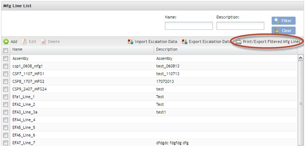
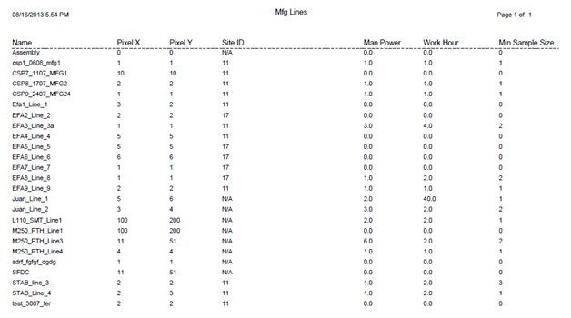
1. Select Print/Export Filtered Mfg Lines. A report is generated and the user is able to save the file or print it.
Figure 7: Print/Export Filtered Mfg Line
Figure 8: Print/Export Filtered Mfg Lines Result
Import Escalation Data
To import escalation data, select Import Escalation Data.
Figure 9: Import Escalation Data
Choose the CVS file and save it.
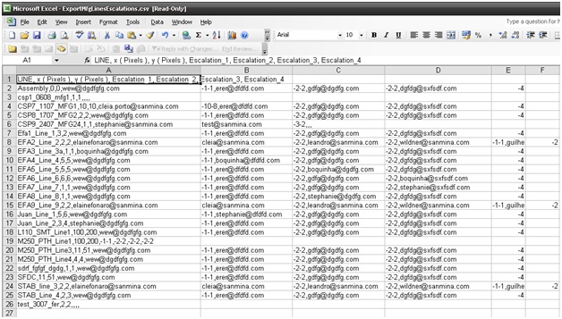
The CVS file has the following format:
SITE (String), LINE (Mfg Line name defined on precondition 2), x (Always empty), y (Always empty), x Pixels (Integer), y Pixels (Integer), Escalation 1, Escalation 2, Escalation 3 and Escalation 4 - see example below (figure 11):
E43_HO,M110_SMT_Line_1,,,100,200,e-mail;email;-1-3-30,e-mail;-4-5-30,e-mail;-6-10-30,e-mail;-10-15-30
E43_HO,M200_ICT_Line_1,,,100,200,e-mail;email;-1-3-30,e-mail;-4-5-30,e-mail;-6-10-30,e-mail;-10-15-30
NOTE: CSV file format is the same currently in use by plants to maintaining SOMS Escalation and map coordinates.
Export Escalation Data
This portlet will export all escalation Data and save it in a ZIP file.
1. Choose the local directory and select Save. The ZIP file with the CSV file will be saved locally.
Figure 10: Export Escalation Data
Figure 11: CSV File Generated.
Appendix
Glossary
Access Control
it is a module that will set the permissions for users and external customers of Sanmina
administrator
the System Administration has full access - all plants, all reports, all users.
component
A component is a specific piece of data that appears on a label, for example: bar code, part numbers, graphic images, line or text. Hence, label components are broken down into several different types: text, graphic images, MDS database values, or a combination of text and database values.
framework
In software development, a framework is a defined support structure in which another software project can be organized and developed. A framework may include support programs, code libraries, a scripting language, or other software to help develop and glue together the different components of a software project.
SFDC Configuration
The rules used to define how SFDC collects data, provides analysis, controls processing and maintains unit histories
Site Minder
Universal login of Sanmina
username
the username is the siteminder username (or a partial string)
Document Revision History
| Date | Author | Title | Version | Change Reference |
| 08/16/13 | Elaine Fonaro | Technical Writer | v 1.0 | This is the first revision of MDS User’s Guide |
| 02/10/14 | Dane Parker | Technical Writer | v 1.0 | Grammar and images review |
| 02/12/14 | Elaine Fonaro | Technical Writer | v 1.0 | Formatting |

