Difference between revisions of "SOP-42Q-MES0149 Reprocessing Defect"
| Line 83: | Line 83: | ||
| | ||
| − | === <span class="mw-headline" id="Failure_Found"><span class="mw-headline" id="Failure_Found"><span class="mw-headline" id="Failure_Found"><span class="mw-headline" id="Failure_Found"><span class="mw-headline" id="Failure_Found"><span class="mw-headline" id="Failure_Found"><span class="mw-headline" id="Failure_Found"><span class="mw-headline" id="Failure_Found"><span class="mw-headline" id="Failure_Found"><span class="mw-headline" id="Failure_Found">Failure Found</span></span></span></span></span></span></span></span></span></span> === | + | |
| + | === <span class="mw-headline" id="Failure_Found"><span class="mw-headline" id="Failure_Found"><span class="mw-headline" id="Failure_Found"><span class="mw-headline" id="Failure_Found"><span class="mw-headline" id="Failure_Found"><span class="mw-headline" id="Failure_Found"><span class="mw-headline" id="Failure_Found"><span class="mw-headline" id="Failure_Found"><span class="mw-headline" id="Failure_Found"><span class="mw-headline" id="Failure_Found"><span class="mw-headline" id="Failure_Found"><span class="mw-headline" id="Failure_Found">Failure Found</span></span></span></span></span></span></span></span></span></span></span></span> === | ||
'''Failure Found''' in marked with Number '''1''' on the screen - is a quality event that is identified by a unique ‘Re-processing ID’. In this phase and after introducing the Serial Number, the Part number is populated. Failure Found will highlight and display the following values to be able to process the failure: | '''Failure Found''' in marked with Number '''1''' on the screen - is a quality event that is identified by a unique ‘Re-processing ID’. In this phase and after introducing the Serial Number, the Part number is populated. Failure Found will highlight and display the following values to be able to process the failure: | ||
*'''Test Section: '''This data is obtained directly from the autotest the machine performs on itself and it refers to the section where the failure is located, the user is able to see and choose from a drop-down list all possible modules where the failure is located. | *'''Test Section: '''This data is obtained directly from the autotest the machine performs on itself and it refers to the section where the failure is located, the user is able to see and choose from a drop-down list all possible modules where the failure is located. | ||
| − | **'''Test Section Description: ''' | + | **'''Test Section Description: '''This is auto-populated after the main field has an option selected. |
| | ||
| − | '''Figure 5: Test Section | + | '''Figure 5: Test Section''' |
| + | |||
| + | [[File:RD TestSection.png|900px]] | ||
| + | |||
| + | | ||
| − | ''' | + | '''Test Step: '''The information in the drop-down list shows up accordingly with the previously selected Test section and it refers to the specific step where the failure presents. |
| − | + | *'''Test Step Description: '''This is auto-populated after the main field has an option selected. | |
| − | |||
| | ||
| − | '''Figure 6: Test Step | + | '''Figure 6: Test Step''' |
| + | |||
| + | [[File:RD TestStep.png|900px]] | ||
| + | |||
| + | | ||
| − | ''' | + | '''Message code: '''This information comes from the autodiagnostic. |
| − | + | *'''Message: '''It is auto-populated after the main field has an option selected. | |
| − | |||
| | ||
| − | '''Figure 7: Test Section Description, Test Step Description, Message | + | '''Figure 7: Test Section Description, Test Step Description, Message''' |
| − | [[File: | + | [[File:RD TestStationandStepDescriptionMessage.png|900px]] |
| | ||
| Line 126: | Line 133: | ||
'''Figure 8: Reprocessing ID: ''' | '''Figure 8: Reprocessing ID: ''' | ||
| − | + | [[File:RD ReprocessingID.png|900px]] | |
| − | |||
| − | |||
| − | |||
| − | |||
'''<u>Note:</u> '''The Reprocessing ID replaces Phase 1: Failure Found and leads the user to Phase 2: Troubleshooting. | '''<u>Note:</u> '''The Reprocessing ID replaces Phase 1: Failure Found and leads the user to Phase 2: Troubleshooting. | ||
| − | |||
| − | |||
| − | |||
| − | |||
| | ||
Revision as of 06:38, 21 February 2024
Contents
Introduction
The Reprocessing Defect is a 42Q portlet, which provides the users with the ability to diagnose and capture the failure analysis, reducing the repair time and mitigating human error in manual tracking, while systematically capturing and tracking across multiple systems, such as NCMR (Non-Conformance Material Request) and MESWeb without duplicate data entry.
To access the Reprocessing Defect from the 42-Q portal navigate to Shop Floor Control > Production Control > Reprocessing Defect.
See the next topics for further details on how to use the Reprocessing Defect.
Reprocessing Defect
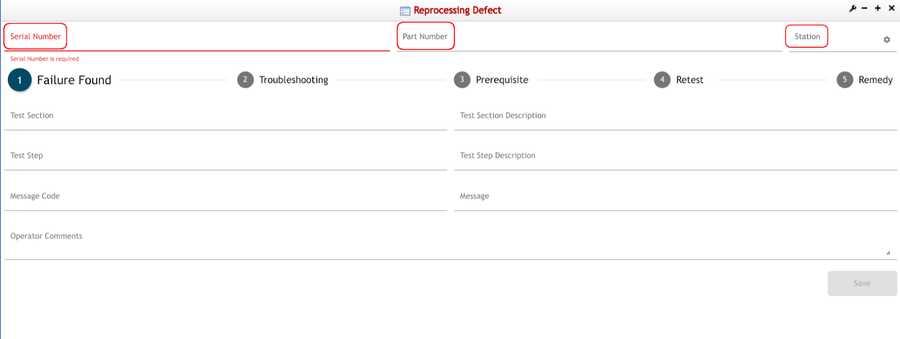
At the top of the Reprocessing Defect landing page, the header displays the Serial Number, Part Number, and Station fields.
Figure 1: Reprocessing Defect Sections
Station
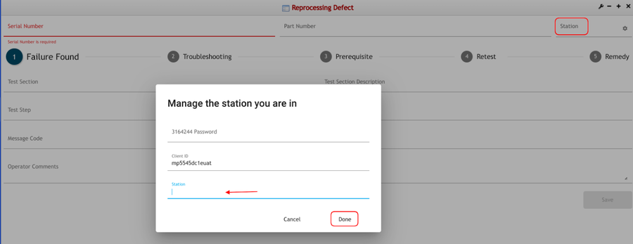
Station is the starting point to select the location/process/device where the final inspection happened and failure was reported; by selecting Station, the system will automatically pop up a window requesting employee validation password and the location, process, or device, where work is required.
To set up the location, process, or device, select Station:
Figure 2: Station
Serial Number and Part Number
Once the location, process, or device is set up, the serial number is required; The system would automatically populate the Part Number field based on the imputed Serial Number.
Note: The Serial Number can either be scanned or added manually.
Figure 3: Serial and Part Number
Reprocessing Defect Phases
In the next topics listed below, see the details for the phases available for the Reprocessing 'Defect' process:
- Failure Found
- Troubleshooting
- Prerequisite
- Reset
- Remedy
Figure 4: Reprocessing Defect Phases
Failure Found
Failure Found in marked with Number 1 on the screen - is a quality event that is identified by a unique ‘Re-processing ID’. In this phase and after introducing the Serial Number, the Part number is populated. Failure Found will highlight and display the following values to be able to process the failure:
- Test Section: This data is obtained directly from the autotest the machine performs on itself and it refers to the section where the failure is located, the user is able to see and choose from a drop-down list all possible modules where the failure is located.
- Test Section Description: This is auto-populated after the main field has an option selected.
Figure 5: Test Section
Test Step: The information in the drop-down list shows up accordingly with the previously selected Test section and it refers to the specific step where the failure presents.
- Test Step Description: This is auto-populated after the main field has an option selected.
Figure 6: Test Step
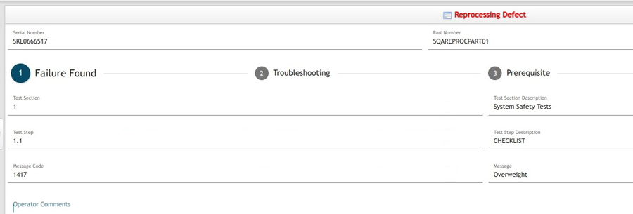
Message code: This information comes from the autodiagnostic.
- Message: It is auto-populated after the main field has an option selected.
Figure 7: Test Section Description, Test Step Description, Message
Note: Test Section Description, Test Step Description, and Message are auto-populated after the main field on the left side has an option selected.
- Operator Comments: This is a non-mandatory field; however if there is any extra or more specific information that might be useful through the process it can be added here.
The Reprocessing ID is created only after all the information, unique to the serial, customer test step, and customer test code is completed and the user clicks Save; then Failure Found title would be replaced by the Reprocessing ID. This number will be used throughout the whole process and will serve as an identifier for the Reprocessing report.
Figure 8: Reprocessing ID:
Note: The Reprocessing ID replaces Phase 1: Failure Found and leads the user to Phase 2: Troubleshooting.
Troubleshooting
Troubleshooting is marked with Number 2 - incorporates all the actions carried out by a production technician that eventually could lead to a successful remedy action. Right after Failure Found information is saved and Reprocessing ID is generated, the Troubleshooting screen is displayed. This is where tracking begins, but first, the action’s information is required.
Troubleshooting is divided into 3 sections: New Action, Remove and Reinstall Action, and Summary.
Figure 9: Troubleshooting Section
10- RN TrobleshootingSection.jpg
Note: The user needs to click to open and display each of the sections.
In the first section, the user is able to see New Action, New form, and the No Defect button.
The No Defect button is used to state no action was performed in Troubleshooting and send the user directly to the Retest section.
Once the user clicks on the name the following list will display:
- Impacted Serial: User must provide the serial number of the Assembly or Subassembly that would be impacted by the performed action
- Impacted Part Number: Auto Populates after the Impacted Serial is entered.
- Action Code: Code of the action that is going to be performed to fix the failure. The available options will be displayed.
- Action Code Description: This field is auto-populated according to the selected action code.
- Action Taken on: Three options are available for this field; selection must be made depending on the available information the user has about the actual item where the troubleshooting action is taking place.
- Serial: Select this if the affected part is a serialized item.
- Part: Select this if the affected part is a non serialized item.
- LPN: Select this if the affected part is a non tracked component.
Note: When LPN is selected, a new set of sections is displayed: LPN part number, LPN serial Number, Defect Code, and Defect Code Description.
- Defect Code: Available defect code will display.
- Defect Code Description: Is automatically populated after the selected Defect Code.
Figure 10: Troubleshooting: New Action:
'Note: '+More button at the bottom of each section is for adding another action, and the trash can button allows the user to remove an action.
The second module is Remove and Reinstall action and consists of the following:
Action taken on: Same as the above action taken on as three options; selection must be made depending on the available information the user has about the actual item where the troubleshooting action is taking place.
Serial: Select this if the affected part is a serialized item.
Part: Select this if the affected part is a non serialized item.
LPN: Select this if the affected part is a non tracked component.
Figure 11: Troubleshooting: Remove and Reinstall Action:
12- RN RemoveandReinstallaction.jpg
The third module only contains the Summary:
Summary: This field is where the system displays the troubleshooting actions that are going to be performed based on the information the user has provided so far.
The image below shows what the Summary displays; Date, Operator, Action taken, Part Number.
Figure 12: Summary:
Note: At this point, the user is able to click Save and Submit and is also able to do partial saves at any point and come back. When the user selects Submit, the next step will be available.
Prerequisite
This section is marked with Number 3 - it works as a quality assurance to test if the performed troubleshooting action was performed correctly as the actions could have impacted in some other areas. The prerequisites are established by the customer; and the ones that are displayed depend on the failure, section, module and action to be taken.
The user is able to see the following on the screen:
Conditional Testing who contains the Test section, Test step, Passed or Failed, and Message code.
Figure 13: Prerequisite Screen:
Note: When the user clicks on Passed, the circle will turn green, if the user clicks on Failed the circle will turn red and the message code will be necessary. Only after one of the options is selected, Summary will appear at the bottom of the screen.
Figure 14: Prerequisite Passed:
Figure 15: Prerequisite Failed:
Depending on the case, the Prerequisite’s page could appear empty; however, the user is free to select the ones considered necessary and execute them, but on the other hand, if the system happens to display information, there could be three types of prerequisites:
- Retest-Guideline tests.
A Retest-Guideline is a mandatory procedure and can be the same as the failed step or the previous test steps, must be executed whenever a part is removed, regardless of whether it was removed to be replaced for a new one or to give access to other parts and later re-inserted (without replacing it with a new one).
Sometimes a Retest-Guideline procedure is at the same time a prerequisite for a troubleshooting action retest; if that is the case, the retest-guideline actions would not appear as Prerequisites step(s), due to user must have already performed that process anyway and there is no point on executing them again.
Note: If the user considers that the defined prerequisites are not enough and an extra test is necessary (or several are) he/she can add them directly from the drop-down menu.
Figure 16: Types of Prerequisites
17- RN TypesofPrerequisites.png
- Prerequisites.
The prerequisite tests are actions that might need to be executed before the unit’s retest.
- Conditional Testing
The steps that appear in this section are not mandatory; however, the operator must consider whether it would be better to execute them or not. “Conditional Tests” prerequisites, are additional tests that may be requested by the customer or requested as a test step to be performed for special case units.
Note: The user cannot move forward unless all the Prerequisites are fulfilled and once those are passed, the system will indicate that the unit is ready for retesting.
Retest
Retest the failed test step and record results, marked with Number 4 - After troubleshooting actions were taken and the prerequisites were successfully fulfilled, the retest is performed in the unit and if the retest does not show any problem, it means that the performed troubleshooting action was successful and fixed the failure, so the user can move on to the Remedy;
Figure 17: Retest Screen
Note: If the test shows either the same message code or a different one, their both return to Troubleshooting, the difference is that when the message code is different then a new Reprocessing ID will be generated for the new Troubleshooting actions to be performed in order to solve the current problems.
In the Retest screen, the user is able to see the Retest Guideline who incorporates the Test section the Test step who are predetermined by the test section and test step in Failure found (step 1) also the options Passed or Failed, where the user can manually confirm whether the failure pass or failed.
Figure 18: Retest: Passed
Note: When the user clicks on''''Passed' , the circle will turn green, if the user clicks on 'Failed' the circle will turn red and the message code will be necessary; only after one of the options is selected 'Summary' will appear at the bottom of the screen.
Figure 19: Retest: Failed
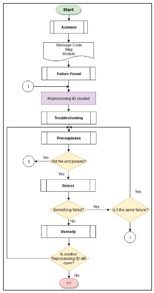
The workflow is better explained in the following diagram.
Figure 20: Reprocessing Defect Workflow Diagram:
Remedy
Shows the successful action or actions (if more than 1 action done during a troubleshoot that fixes the failed test step for a reprocessing report ID:
- Action carried out (example: Replaced)
- Action on Part: The part in which the action was taken on.
- Defect on Part: The defect Code and description.
- Select NCMR: For an action ‘Replaced’, it is the operator’s decision to Select NCMR or not. However, for actions other than ‘Replaced’ there should be NO possibility to select NCMR.
Once a Retest shows a failure was corrected, that action should be defined as“Remedy”.
If everything passes, then the user is able to see the Summary, describing the previous steps and the iteration number which indicates how many times the user has taken actions in the serial, but only if NCMR is selected, the information should be added next to the originating Reprocessing ID.
Figure 21: Remedy
Reports
All actions saved in the activities tables will be visible as Reports using MESWeb; Unit Action History and Unit History, as listed in the following steps.
Unit Action History
The following steps display how the Unit Action History behaves when the user searches for a Serial Number that was used in the Reprocessing Defect screen.
Figure 22: Unit Action History
RD Unit Action History Serial.png
By placing a previously processed Serial Number in the Reprocessing Defect application (Step 2 in MESWEb as displayed in the image above), the user is able to see a report of the steps performed by pressing the Go button.
'Note: 'Iteration and the number indicates that it is the first (second, third, fourth, etc.) time that the user has taken an action in Troubleshooting because is possible to create different iterations inside a Reprocessing ID or to create another Reprocessing Id if the Serial presents a different defect and at the same time this one can generate more than one iteration.
Figure 23: Unit Action History Report- Iteration 1
Figure 24: Unit Action History Report- Iteration 2
This report displays detailed information or the “history” in the first and last Reprocessing ID; such as the action performed, the defect description, and whether it passes or fails the tests.
Unit History
Unit History has the same steps as the Unit Action History, the user must enter the previously processed Serial Number and select the Go button.
Note: The Unit History will only display the latest iterations actions recorded in the Reprocessing Defect Application.
Figure 25: Unit History Report
By selecting the Flashlight icon in the Recorded Defect; the user is able to see what defects are linked to such defects, the structure, defects recorded, and the actions taken in the Troubleshooting step.
Note: The Unit History Report gives detailed information about a specific unit and all its activity throughout its lifecycle. This allows users to see information about a specific unit and its activity.
For more information please refer to the MESWeb SOP.


