Difference between revisions of "SOP-MES0002 Assembly Maintenance"
| Line 364: | Line 364: | ||
| | ||
| − | === <span class="mw-headline" id="Print_Shop_Floor_ID_Assemblies"><span class="mw-headline" id="Print_Shop_Floor_ID_Assemblies"><span class="mw-headline" id="Print_Shop_Floor_ID_Assemblies"><span class="mw-headline" id="Print_Shop_Floor_ID_Assemblies"><span class="mw-headline" id="Print_Shop_Floor_ID_Assemblies"><span class="mw-headline" id="Print_Shop_Floor_ID_Assemblies"><span class="mw-headline" id="Print_Shop_Floor_ID_Assemblies"><span class="mw-headline" id="Print_Shop_Floor_ID_Assemblies"><span class="mw-headline" id="Print_Shop_Floor_ID_Assemblies"><span class="mw-headline" id="Print_Shop_Floor_ID_Assemblies"><span class="mw-headline" id="Print_Shop_Floor_ID_Assemblies"><span class="mw-headline" id="Print_Shop_Floor_ID_Assemblies">Print Shop Floor ID Assemblies</span></span></span></span></span></span></span></span></span></span></span></span> === | + | |
| + | === <span class="mw-headline" id="Print_Shop_Floor_ID_Assemblies"><span class="mw-headline" id="Print_Shop_Floor_ID_Assemblies"><span class="mw-headline" id="Print_Shop_Floor_ID_Assemblies"><span class="mw-headline" id="Print_Shop_Floor_ID_Assemblies"><span class="mw-headline" id="Print_Shop_Floor_ID_Assemblies"><span class="mw-headline" id="Print_Shop_Floor_ID_Assemblies"><span class="mw-headline" id="Print_Shop_Floor_ID_Assemblies"><span class="mw-headline" id="Print_Shop_Floor_ID_Assemblies"><span class="mw-headline" id="Print_Shop_Floor_ID_Assemblies"><span class="mw-headline" id="Print_Shop_Floor_ID_Assemblies"><span class="mw-headline" id="Print_Shop_Floor_ID_Assemblies"><span class="mw-headline" id="Print_Shop_Floor_ID_Assemblies"><span class="mw-headline" id="Print_Shop_Floor_ID_Assemblies">Print Shop Floor ID Assemblies</span></span></span></span></span></span></span></span></span></span></span></span></span> === | ||
This functionality allows the user to print or export Assemblies for the selected Line. The report prints to the default printer for the workstation. | This functionality allows the user to print or export Assemblies for the selected Line. The report prints to the default printer for the workstation. | ||
| Line 374: | Line 375: | ||
'''Figure 15: Print SShop Floor ID Assemblies''' | '''Figure 15: Print SShop Floor ID Assemblies''' | ||
| − | [[File:AM PrintShopFloorIDAssemblies.png|900px]] | + | [[File:AM PrintShopFloorIDAssemblies.png|900px|AM PrintShopFloorIDAssemblies.png]] |
| − | + | A pop-up prompts the user to select the appropriate Shop Floor ID. | |
2. Select a Shop Floor ID from the drop-down box. | 2. Select a Shop Floor ID from the drop-down box. | ||
Revision as of 18:09, 9 January 2023
42Q Home > Shop Floor Control > Configuration > Assembly Maintenance
Contents
- 1 Shop Floor Configuration Setup
- 2 Assembly Maintenance
Shop Floor Configuration Setup
42Q’s powerful data collection system collects critical information from a plant’s shop floor, utilizing a shop floor data collector, an intuitive tool developed by 42Q’s experienced manufacturing team. The aggregate information is stored in a cloud database, and available to MESWeb, where quality reports are generated. The 42Q system uses manual and automated barcode scanning to collect data for a product line or plant. Thus, 42Q plays an important role in maintaining unit histories and directing product movement on the manufacturing floor. The current version of 42Q includes configuration capabilities, which provide access to all sub-module pages and their functionalities (view, add, edit, print/generate output files).
Assembly Maintenance
Assembly Maintenance defines the components or sub-assemblies that are merged into the main product. Also defined are the Data Collection Locations where sub-assemblies are merged and prompts displayed to the operator. Assembly Maintenance tables are configured to perform serial, part, and location validation of items merged to the main product.
This module defines the procedures for assembling a product, along with the steps for each component’s integration. When the user enters information into the workstation, the description of how to perform specific labor will display. This description is available on the scanner, located at the station display, and may also inform the user of the exact location of where the component should be placed in the part.
To access the Assembly Maintenance, navigate to Shop Floor Control > Configuration > Shop Floor Configuration > Assembly.
Figure 1: Assembly Maintenance
Note: A user only has access to the modules assigned to his/her profile.
List Assemblies
Based on the actual Shop Floor Configuration, the application displays a list of all Assemblies.
To list assemblies, select Assembly from the Shop Floor Configuration Maintenance menu.
Note: The user only has access to this module if it has been added to his/her profile.
Filter Assemblies
There are three available filter fields: Shop Floor ID, Location, and Part.
1. Enter desired filter criteria and select Filter.
2. To clear the filter fields, select Clear. The filter result is displayed in the Assembly list.
Figure 2: List and Search
3. The filter result is displayed in the Assembly list.
From the Assembly List, the user is able to manage the assemblies as Add, Step List, Copy, Delete, Print/Export, Publish History, Import, Export, Print Shop Floor ID Assemblies, Print Filtered Assemblies, and Print All Installed Steps.
The user is able to use the pagination feature to navigate between the Assemblies pages.
Add Assembly
This functionality allows users to add an assembly.
1. To add an assembly, select the Add button.
Figure 3: Add Assembly
The Assembly form is displayed. The user must populate all mandatory fields when adding assembly steps. If the mandatory fields are not populated, an error message is displayed.
Note: When adding an Assembly the user must define a Part Number. However, when creating an Assembly Step (below), defining a Part Number is not mandatory.
2. Select the appropriate location from the Location drop-down box.
3. Enter the appropriate part number in the Part Number field.
4. Select Save to create the assembly.
5. Leave the Part Number field blank if the assembly will be configured for all parts.
(Leave the Part Number field blank if the assembly will be configured for ALL Parts.)
6. After this step validates the entered information in the database, the Assembly Step List page is displayed.
Note: The user must add at least one step to the Assembly for it to be saved in the system.
7. To add a step to the created Assembly, select the Add Assembly Step, enter the appropriate information, and select Save.
List Steps
This functionality displays a list of all Assembly Steps.
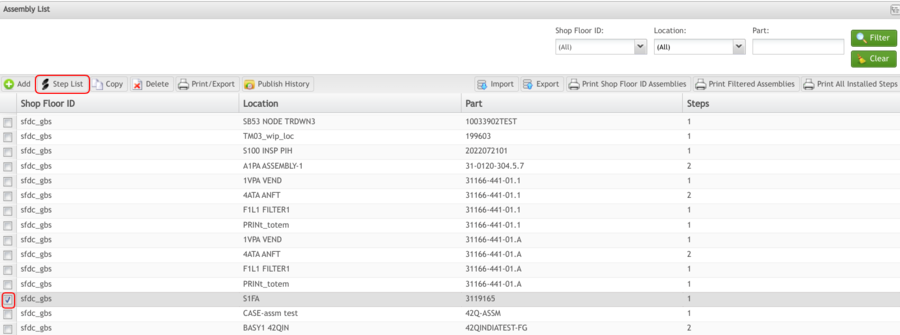
1. To access the Assembly Step menu, the user must first check the box to the left of the appropriate Shop Floor ID, then select Step List.
Figure 4: Assembly List – Step List
Add Assembly Step
This functionality adds an assembly step to the system.
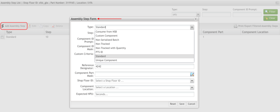
To add an assembly step, select Add Assembly Step from the step list screen.
The Assembly Step List enables the following tasks:
- Add Assembly Step
- Edit, Copy and Delete
- Print/Export Filtered Assembly Steps
Figure 5: Add Assembly Step
The user must populate all mandatory fields (indicated in Red) when adding assembly steps. If the mandatory fields are not populated, an error message is displayed.
Type
The type of Assembly Step that is being created. The following types are available:
- Consume for NSB - is used when there must be a Non-Serialized Batch (NSB) serial available, using the same assembly rules as with a tracked component [matching the comp_id_mask, with a part number that the component_part mask specifies, and at the location specified by comp_loc_key or by OPTIONS COMPONENT STATUS].
- Custom Component: A component that requires development for customized validations prior to being added to an assembly.
- Non-Serialized Batch
- Non-Tracked - A component that is not tracked prior to being added to an assembly.
- Non-Tracked with Quantity - is used when there is no Non-Serialized Batch (NSB) serial expected to be available.
- PTS ID - A component that is tracked via the Parts Traceability System prior to being added to an assembly.
- Standard - A component that is tracked prior to being added to an assembly. These components have their own Unit History and MUST be completed prior to being added to an assembly.
- Unique Component - A component that is not tracked prior to being added to an assembly. A serial record for these components is generated dynamically upon being scanned into an upper-level assembly. This ensures that this component cannot be added to any other build unless first removed from the prior build
Step
The number is automatically generated by the Step Number function.
- Component ID Prompt
The prompt is displayed to the operator upon scanning the main assembly. This prompt should specify the sub-assembly being added to the main assembly. The prompt length can be up to 16 characters. This prompt is only displayed if the sub-assembly has not been previously installed at this station.
Note: If another Location has the same Process Name with the same Assembly sequence and the main assembly is scanned there (because of a Manual Move), Shop Floor prompts for the sub-assemblies to be installed even if they were installed previously.
Note: If the OPTIONS ASM_BY_PROCNAME=YES option is installed in the Setup Data Editor Form, the component prompt is displayed for all Locations with the same Process Name that is assigned to the Location in which the assembly is configured.
Note: For further information about options, see SOP-5-I-SFDC0010-C-SFDC SDE Quick Reference under the Options section.
- Component Id Mask
The serial mask of the sub-assembly. The maximum length of the data field is 40 characters. The maximum length of a single ID mask is 20 characters. Multiple ID masks are separated by a comma (,).
- Reference Designator
The reference designator (or nomenclature) of the sub-assembly. This is a text string up to 22 characters in length. When a new Component ID prompt is entered for a step, this data field contains the same default value. The field is editable.
- Component Part
The part number of the sub-assembly being added to the main assembly. It must exist in the Part Table and is only needed if the Component ID mask is the same for multiple products.
Note: Any valid part mask is acceptable for Non-Tracked, Standard, or PTS ID assembly step types. More than one part number separated by a comma is an acceptable part mask.
Note: Once the component part number is entered, the Shop Floor ID field will be available to populate.
- Shop Floor ID
The ID of the Shop Floor associated with the assembly step.
Note: Once the Shop Floor ID is chosen, the Component Location field will be available to populate.
- Component Location
Valid only if the sub-assembly is tracked. This is the Location where the sub-assembly is expected to be. Using this data field ensures the sub-assembly is ready to be installed into the main assembly.
- Expected HPU
Enter the expected HPU in seconds.
Once all the required information has been entered, select Save. To exit, select Cancel. To clear all fields, select Clear.
The new assembly step is displayed in the list.
Note: For further information concerning mask characters and their respective definitions, see SOP-5-I-42Q-MES0099-C Mask Characters for reference. Documentation applies to Assembly, Attribute Definition Maintenance, and SDE (sub)modules.
Edit Assembly Step
This functionality allows modification of any available Assembly Steps. If a mandatory field is not populated, an error message is displayed.
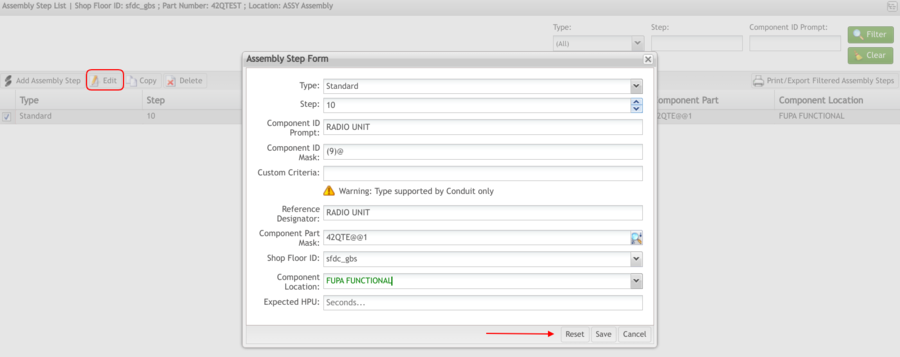
1. To edit an assembly step, select an existing assembly step, then select Edit.
Figure 6: Assembly Step List – Edit
2. Edit the necessary field(s) then select Save.
Copy Assembly Step Data
This functionality allows the user to copy data from one assembly step to another.
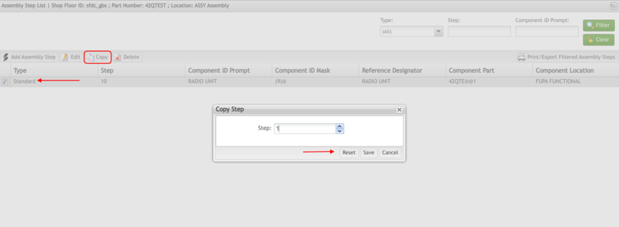
1. To copy assembly step data, select an existing assembly step, then select Copy.
Figure 7: Assembly Step List – Copy
The Copy Step pop-up is displayed:
2. Enter the desired step that will be a copy of the originally selected step.
3. Select Save to confirm.
4. The data from the originally selected step will be copied to the new step.
Delete Assembly Step
This function deletes the selected Assembly Step.
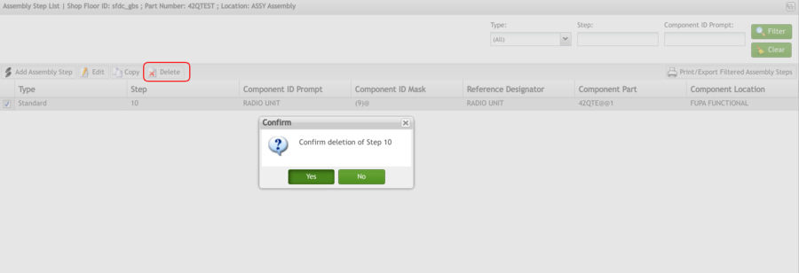
1. To delete an assembly step, select an existing step, then select Delete. A confirmation message is displayed.
Figure 8: Assembly Step List – Delete
2. Select Yes to confirm the deletion. Select No to cancel.
Print/Export Filtered Assembly Step
This functionality prints the current filtered list of steps. The report prints to the default printer for the workstation. The system displays print result information.
1. To print all assembly steps, select the Print/Export Filtered Assembly Step.
Figure 9 Print Filtered Assembly Steps
A PDF report is generated and the user is able to save the file locally.
Select Save to save the report results, or select Print to print the report results.
Save/Publish
The Save/Publish Conduit-based function at the bottom of the Assembly Step List screen is available to users with the appropriate permissions and can be used by selecting the down arrow adjacent to the Save button. Whereas Save gives the record a pending status relative to Conduit, Save/Publish saves the record and publishes it to Conduit.
Copy Assembly
This functionality allows the user to copy data from one Local Assembly to another part.
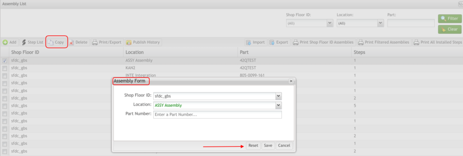
1. To copy Local Assembly to another part, select an existing Assembly, then select Copy.
Figure 10: Assembly List - Copy Assemblies
2. Enter the data and then select Save.
Delete Assembly
This functionality allows users to delete the selected Local Assembly.
1. To delete Local Assembly, select the Assembly to be deleted, then select Delete.
Figure 11: Assembly List - Delete Assemblies
A confirmation message is displayed. Select Yes to confirm or No to exit.
Import/Export
The Import and Export functions allow the user to import an Assembly into the database via a CSV spreadsheet. Similarly, the Export function allows the user to export Assembly database information as a CSV and save it to a local destination.
Note: CSVs that are to be imported must adhere to a specific template. This template can be acquired by selecting Get Template in the Import Attribute window.
Figure 12: Import Attribute Window
Print/Export Assembly
This functionality allows the user to generate an output file with the Assembly contents.
1. To export assemblies, select Print/Export.
Figure 13: Assembly List - Print/Export Assemblies
A PDF report is generated and the user is able to save the file or print it from an external program.
Publish History
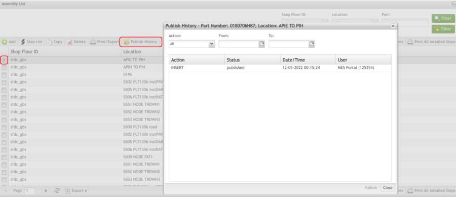
For sub-modules that use Conduit, the Publish History functionality can also be found in the menu bar by users with the appropriate permissions. The Publish History function shows the action history of an item. With this functionality, the user can publish an action history record to the Conduit.
Figure 14: Publish History - Conduit Function
Print Shop Floor ID Assemblies
This functionality allows the user to print or export Assemblies for the selected Line. The report prints to the default printer for the workstation.
1. To print/export Shop Floor ID Assemblies for the selected Shop Floor ID, select Print Shop Floor ID Assemblies on the menu. A pop-up appears prompting the user to select the appropriate Shop Floor ID.
Figure 15: Print SShop Floor ID Assemblies
A pop-up prompts the user to select the appropriate Shop Floor ID.
2. Select a Shop Floor ID from the drop-down box.
3. A PDF report is generated.
Print Filtered Assemblies
This functionality allows the user to print the Assembly Steps of filtered assemblies. The report prints to the default printer for the workstation.
1. Select the desired filter criteria to obtain the desired list of assemblies to print.
2. Select Print Filtered Assemblies on the menu.
Figure 16: Print Filtered Assemblies
3. A PDF report is generated.
Print All Installed Steps
This functionality allows the user to print all installed assembly steps. The report prints to the default printer for the workstation.
1. Select Print All Installed Steps in the Assembly List menu to print all installed steps. A pop-up appears prompting the user to select the appropriate Shop Floor ID.
Figure 17: Print All Installed Steps
2. Select a Shop Floor ID from the drop-down box.
3. A PDF report is generated.


