Difference between revisions of "SOP-42Q-MES0078 Kit Verify Layout"
(Created page with "<small>Cirrus > Shop Floor Control > Production Control > Kit Verify</small> <br> [[Image:Sanmina logo.png|130px|Sanmin...") |
|||
| Line 22: | Line 22: | ||
*KV Control- responsible for consolidation, integration, inspection, and repair of the kit. | *KV Control- responsible for consolidation, integration, inspection, and repair of the kit. | ||
| − | + | <br> | |
== KV Layout Configuration == | == KV Layout Configuration == | ||
| Line 32: | Line 32: | ||
All available Layout Configurations are listed by Part Number, Project, and Model. | All available Layout Configurations are listed by Part Number, Project, and Model. | ||
| + | <br> | ||
| + | '''Figure 1: KV Layout Config'''<br> | ||
| − | + | [[Image:SOP-5-I-MES0078-C_KV-Layout-Config.jpg]]<br> | |
| − | |||
| − | [[Image: | ||
| Line 48: | Line 48: | ||
2. The layout list will display the layouts according to the user<nowiki>’</nowiki>s entries: | 2. The layout list will display the layouts according to the user<nowiki>’</nowiki>s entries: | ||
| − | + | <br> | |
'''Figure 2: Filter''' | '''Figure 2: Filter''' | ||
| − | [[Image: | + | [[Image:SOP-5-I-MES0078-C_Filter.jpg]]<br> |
| − | |||
| + | <br> | ||
NOTE: To begin a new search, select '''Clear''' to empty the fields and re-enter information into the available fields. | NOTE: To begin a new search, select '''Clear''' to empty the fields and re-enter information into the available fields. | ||
| Line 64: | Line 64: | ||
1. To add a layout configuration, select the '''Add '''icon located above the Part Number list. | 1. To add a layout configuration, select the '''Add '''icon located above the Part Number list. | ||
| − | + | <br> | |
'''Figure 3: Add Layout Configuration''' | '''Figure 3: Add Layout Configuration''' | ||
| − | [[Image: | + | [[Image:SOP-5-I-MES0078-C_Add-Layout-Configuration.jpg]]<br> |
| − | |||
| + | <br> | ||
2. The Layout Configuration portlet displays: | 2. The Layout Configuration portlet displays: | ||
| − | + | <br> | |
'''Figure 4: Layout Configuration''' | '''Figure 4: Layout Configuration''' | ||
| − | [[Image: | + | [[Image:SOP-5-I-MES0078-C_Layout-Configuration.jpg]]<br> |
| − | |||
| + | <br> | ||
3. Select the part number for a Shop Order that contains components with reference designators configured from the '''Part '''fuzzy search field. | 3. Select the part number for a Shop Order that contains components with reference designators configured from the '''Part '''fuzzy search field. | ||
| − | + | <br> | |
NOTE: The '''Project '''and '''Model '''fields are optional, but assist in the description of the layout configuration. | NOTE: The '''Project '''and '''Model '''fields are optional, but assist in the description of the layout configuration. | ||
| − | + | <br> | |
4. After selecting the part number, select the add icon from the tab below the '''Part '''field to upload an assembly layout. | 4. After selecting the part number, select the add icon from the tab below the '''Part '''field to upload an assembly layout. | ||
| Line 94: | Line 94: | ||
5. A Confirm pop-up displays. Select '''Yes '''to open the '''File Upload''' screen. | 5. A Confirm pop-up displays. Select '''Yes '''to open the '''File Upload''' screen. | ||
| − | + | <br> | |
'''Figure 5: Upload Assembly Layout''' | '''Figure 5: Upload Assembly Layout''' | ||
| − | [[Image: | + | [[Image:SOP-5-I-MES0078-C_Upload-Assembly-Layout.jpg]]<br> |
| − | |||
| + | <br> | ||
6. Select the assembly layout image file from the '''File Upload '''screen, and then select '''Open'''. | 6. Select the assembly layout image file from the '''File Upload '''screen, and then select '''Open'''. | ||
| Line 106: | Line 106: | ||
7. The image file displays in the first tab, and a subsequent tab is created to add multiple images if needed. | 7. The image file displays in the first tab, and a subsequent tab is created to add multiple images if needed. | ||
| − | + | <br> | |
'''Figure 6: Assembly Layout''' | '''Figure 6: Assembly Layout''' | ||
| − | [[Image: | + | [[Image:SOP-5-I-MES0078-C_Assembly-Layout.jpg]]<br> |
| − | |||
| + | <br> | ||
8. Select a reference designator from the drop down box provided. | 8. Select a reference designator from the drop down box provided. | ||
| Line 122: | Line 122: | ||
11. Select the green check mark at the top right of the image to save the mapping. | 11. Select the green check mark at the top right of the image to save the mapping. | ||
| + | <br> | ||
| + | '''Figure 7: Assembly Layout Mapping''' | ||
| − | + | [[Image:SOP-5-I-MES0078-C_Assembly-Layout-Mapping.jpg]]<br> | |
| − | |||
| − | [[Image: | ||
| − | |||
| + | <br> | ||
12. Users can add multiple mappings by selecting additional reference designators from the '''Reference Designator '''drop down box. | 12. Users can add multiple mappings by selecting additional reference designators from the '''Reference Designator '''drop down box. | ||
| + | <br> | ||
| + | '''Figure 8: Multiple Mappings Example''' | ||
| − | + | [[Image:SOP-5-I-MES0078-C_Multiple-Mapping-Example.jpg]]<br> | |
| − | |||
| − | [[Image: | ||
| − | |||
| + | <br> | ||
13. Once all mappings are created, select '''Save'''. | 13. Once all mappings are created, select '''Save'''. | ||
| Line 144: | Line 144: | ||
14. To return to the '''KV Layout Config '''main page, select '''Close'''. The new Layout Configuration will be added to the list. | 14. To return to the '''KV Layout Config '''main page, select '''Close'''. The new Layout Configuration will be added to the list. | ||
| − | + | <br> | |
=== Edit === | === Edit === | ||
| Line 152: | Line 152: | ||
1. To edit a Layout Configuration, select the layout configuration and then select '''Edit''' from the '''KV Configuration '''main page. | 1. To edit a Layout Configuration, select the layout configuration and then select '''Edit''' from the '''KV Configuration '''main page. | ||
| − | + | <br> | |
'''Figure 9: Edit Layout Configuration''' | '''Figure 9: Edit Layout Configuration''' | ||
| − | [[Image: | + | [[Image:SOP-5-I-MES0078-C_Edit-Layout-Configuration.jpg]]<br> |
| − | |||
| + | <br> | ||
2. The '''Layout Configuration '''portlet displays. The user can add or remove assembly layouts and mappings from this portlet. | 2. The '''Layout Configuration '''portlet displays. The user can add or remove assembly layouts and mappings from this portlet. | ||
| Line 170: | Line 170: | ||
6. Select '''Close '''to return to the '''KV Configuration '''main screen. | 6. Select '''Close '''to return to the '''KV Configuration '''main screen. | ||
| − | + | <br> | |
'''Figure 10: Remove Layout or Mapping''' | '''Figure 10: Remove Layout or Mapping''' | ||
| − | [[Image: | + | [[Image:SOP-5-I-MES0078-C_Remove-Layout-or-Mapping.jpg]]<br> |
| − | |||
| + | <br> | ||
=== Copy === | === Copy === | ||
| Line 186: | Line 186: | ||
2. The '''Copy Layout Mapping '''form displays: | 2. The '''Copy Layout Mapping '''form displays: | ||
| − | + | <br> | |
'''Figure 11: Copy Layout Configuration''' | '''Figure 11: Copy Layout Configuration''' | ||
| − | [[Image: | + | [[Image:SOP-5-I-MES0078-C_Copy-Layout-Configuration.jpg]]<br> |
| − | |||
| + | <br> | ||
3. Either change the Part Number or change/add the Project and Model, and then select '''Save'''. | 3. Either change the Part Number or change/add the Project and Model, and then select '''Save'''. | ||
| Line 204: | Line 204: | ||
1. To obsolete a layout, select the '''Obsolete '''radio button at the top left of the Layout Configuration screen. | 1. To obsolete a layout, select the '''Obsolete '''radio button at the top left of the Layout Configuration screen. | ||
| − | + | <br> | |
'''Figure 12: Obsolete''' | '''Figure 12: Obsolete''' | ||
| − | [[Image: | + | [[Image:SOP-5-I-MES0078-C_Obsolete.jpg]]<br> |
| − | |||
| + | <br> | ||
2. Select '''Save '''to obsolete the layout. | 2. Select '''Save '''to obsolete the layout. | ||
| − | + | <br> | |
NOTE: If the layout is already attached to a kit in KV Control, it will still be available for use. The obsolete function only removes the layout from the list of available layouts for new kits entering the Integration step. | NOTE: If the layout is already attached to a kit in KV Control, it will still be available for use. The obsolete function only removes the layout from the list of available layouts for new kits entering the Integration step. | ||
| Line 228: | Line 228: | ||
To access Kit Browser, navigate to '''Shop Floor Control '''<nowiki>></nowiki> '''Production Control <nowiki>></nowiki> KV Control''', and then select the '''Kit Browser''' icon. | To access Kit Browser, navigate to '''Shop Floor Control '''<nowiki>></nowiki> '''Production Control <nowiki>></nowiki> KV Control''', and then select the '''Kit Browser''' icon. | ||
| − | + | <br> | |
'''Figure 13: Kit Browser''' | '''Figure 13: Kit Browser''' | ||
| − | [[Image: | + | [[Image:SOP-5-I-MES0078-C_Kit-Browser.jpg]]<br> |
| − | |||
| + | <br> | ||
==== Filter ==== | ==== Filter ==== | ||
| Line 242: | Line 242: | ||
1. To filter the Shop Order list, enter a Shop Order Number, Part Number, and/or a Revision into the filter fields provided and then select '''Filter'''. | 1. To filter the Shop Order list, enter a Shop Order Number, Part Number, and/or a Revision into the filter fields provided and then select '''Filter'''. | ||
| − | + | <br> | |
'''Figure 14: Filter Shop Order List''' | '''Figure 14: Filter Shop Order List''' | ||
| − | [[Image: | + | [[Image:SOP-5-I-MES0078-C_Filter-Shop-Order-List.jpg]]<br> |
| − | |||
| + | <br> | ||
NOTE: To begin a new search, select '''Clear''' to empty the fields and re-enter information into the available fields. | NOTE: To begin a new search, select '''Clear''' to empty the fields and re-enter information into the available fields. | ||
| Line 258: | Line 258: | ||
1. To consolidate a kit from Kit Browser, select the Shop Order from the list and then select '''Kit Consolidation'''. | 1. To consolidate a kit from Kit Browser, select the Shop Order from the list and then select '''Kit Consolidation'''. | ||
| − | + | <br> | |
'''Figure 15: Kit Consolidation''' | '''Figure 15: Kit Consolidation''' | ||
| − | [[Image: | + | [[Image:SOP-5-I-MES0078-C_Kit-Consolidation.jpg]]<br> |
| − | |||
| + | <br> | ||
2. The '''Select the Top level Assembly(ies) '''form displays. All available serials are listed in the right column. The user can enter the serial into the field provided, or select the serial from the available column by double clicking on it. | 2. The '''Select the Top level Assembly(ies) '''form displays. All available serials are listed in the right column. The user can enter the serial into the field provided, or select the serial from the available column by double clicking on it. | ||
| Line 270: | Line 270: | ||
3. Once the serial is in the left column, select the Serial Number and then select '''OK''' to open the '''Kit Processing''' portlet. | 3. Once the serial is in the left column, select the Serial Number and then select '''OK''' to open the '''Kit Processing''' portlet. | ||
| − | + | <br> | |
'''Figure 16: Top Level Assemblies''' | '''Figure 16: Top Level Assemblies''' | ||
| Line 276: | Line 276: | ||
[[Image:15 KV.png|700px|15 KV.png]]<br> | [[Image:15 KV.png|700px|15 KV.png]]<br> | ||
| − | + | <br> | |
4. The '''Kit Processing '''portlet displays in the '''Kit Consolidation '''step. | 4. The '''Kit Processing '''portlet displays in the '''Kit Consolidation '''step. | ||
| Line 282: | Line 282: | ||
5. All associated Part Numbers are listed for consolidation. | 5. All associated Part Numbers are listed for consolidation. | ||
| − | + | <br> | |
'''Figure 17: Kit Processing- Consolidation''' | '''Figure 17: Kit Processing- Consolidation''' | ||
| − | [[Image: | + | [[Image:SOP-5-I-MES0078-C_Kit-Processing-Consolidation.jpg]]<br> |
| − | |||
| + | <br> | ||
6. To consolidate the components, select each part number and then enter or scan the Part Number (for Non-Serialized components) or the serial that fits the mask (for Serialized components). | 6. To consolidate the components, select each part number and then enter or scan the Part Number (for Non-Serialized components) or the serial that fits the mask (for Serialized components). | ||
| − | + | <br> | |
'''Figure 18: Consolidation''' | '''Figure 18: Consolidation''' | ||
| − | [[Image: | + | [[Image:SOP-5-I-MES0078-C_Consolidation.jpg]]<br> |
| − | |||
| + | <br> | ||
7. This process zeros out the '''Missing Quantity''', thus consolidating all the components in the kit. | 7. This process zeros out the '''Missing Quantity''', thus consolidating all the components in the kit. | ||
| Line 304: | Line 304: | ||
8. If there are missing components, mark the item as short by selecting the '''Short '''check box in the far right column. | 8. If there are missing components, mark the item as short by selecting the '''Short '''check box in the far right column. | ||
| − | + | <br> | |
'''Figure 19: Consolidated with Short Items''' | '''Figure 19: Consolidated with Short Items''' | ||
| Line 310: | Line 310: | ||
[[Image:18 KV.png|700px|18 KV.png]]<br> | [[Image:18 KV.png|700px|18 KV.png]]<br> | ||
| − | + | <br> | |
9. After consolidating all of the components, select '''Save '''to confirm. | 9. After consolidating all of the components, select '''Save '''to confirm. | ||
| Line 322: | Line 322: | ||
1. To perform a consolidation recall in the Kit Browser portlet, select a Shop Order from the list that has been consolidated and then select '''Consolidation Recall'''. | 1. To perform a consolidation recall in the Kit Browser portlet, select a Shop Order from the list that has been consolidated and then select '''Consolidation Recall'''. | ||
| − | + | <br> | |
'''Figure 20: Consolidation Recall''' | '''Figure 20: Consolidation Recall''' | ||
| Line 328: | Line 328: | ||
[[Image:19 KV.png|700px|19 KV.png]]<br> | [[Image:19 KV.png|700px|19 KV.png]]<br> | ||
| − | + | <br> | |
2. The '''Consolidation Recall '''form displays. Select a Top Level serial and then select '''OK'''. | 2. The '''Consolidation Recall '''form displays. Select a Top Level serial and then select '''OK'''. | ||
| − | + | <br> | |
'''Figure 21: Top Level Serial''' | '''Figure 21: Top Level Serial''' | ||
| Line 338: | Line 338: | ||
[[Image:20 KV.png]]<br> | [[Image:20 KV.png]]<br> | ||
| − | + | <br> | |
3. A confirmation pop-up displays. Select '''Yes '''to continue. | 3. A confirmation pop-up displays. Select '''Yes '''to continue. | ||
| Line 344: | Line 344: | ||
4. The '''Consolidation Recall Result '''pop-up displays with the Serial Number, Part Number, and Component information that has been recalled. | 4. The '''Consolidation Recall Result '''pop-up displays with the Serial Number, Part Number, and Component information that has been recalled. | ||
| − | + | <br> | |
'''Figure 22: Consolidation Recall Result''' | '''Figure 22: Consolidation Recall Result''' | ||
| Line 350: | Line 350: | ||
[[Image:21 KV.png|700px|21 KV.png]]<br> | [[Image:21 KV.png|700px|21 KV.png]]<br> | ||
| − | + | <br> | |
==== Print/Reprint Traveler ==== | ==== Print/Reprint Traveler ==== | ||
| Line 358: | Line 358: | ||
1. To print a traveler, select the Shop Order from the '''Shop Order Number '''list and then select '''Print/Reprint Traveler'''. | 1. To print a traveler, select the Shop Order from the '''Shop Order Number '''list and then select '''Print/Reprint Traveler'''. | ||
| − | + | <br> | |
'''Figure 23: Print/Reprint Traveler''' | '''Figure 23: Print/Reprint Traveler''' | ||
| − | [[Image:22 KV.png|700px|22 KV.png]] | + | [[Image:22 KV.png|700px|22 KV.png]] |
<br> 2. The '''One Traveler Per Unit:: '''form displays. Select the Top Level Assembly serial number and then select '''Print'''. | <br> 2. The '''One Traveler Per Unit:: '''form displays. Select the Top Level Assembly serial number and then select '''Print'''. | ||
| − | + | <br> | |
'''Figure 24: Top Level Assembly''' | '''Figure 24: Top Level Assembly''' | ||
| Line 372: | Line 372: | ||
[[Image:23 kv.png]]<br> | [[Image:23 kv.png]]<br> | ||
| − | + | <br> | |
3. The traveler will prompt to be opened with an external program. Select the program with which to open the file and then select '''OK'''. | 3. The traveler will prompt to be opened with an external program. Select the program with which to open the file and then select '''OK'''. | ||
| Line 378: | Line 378: | ||
4. The traveler will open in the external program for the user to print. | 4. The traveler will open in the external program for the user to print. | ||
| − | + | <br> | |
'''Figure 25: Traveler Sheet''' | '''Figure 25: Traveler Sheet''' | ||
| Line 384: | Line 384: | ||
[[Image:24 KV.png|700px|24 KV.png]]<br> | [[Image:24 KV.png|700px|24 KV.png]]<br> | ||
| − | + | <br> | |
=== Kit Processing === | === Kit Processing === | ||
| Line 402: | Line 402: | ||
3. All associated Part Numbers are listed for consolidation. | 3. All associated Part Numbers are listed for consolidation. | ||
| − | + | <br> | |
'''Figure 26: Kit Processing- Consolidation''' | '''Figure 26: Kit Processing- Consolidation''' | ||
| − | [[Image:25 kv.png | + | [[Image:25 kv.png|25 kv.png]]<br> |
| − | |||
| + | <br> | ||
4. To consolidate the components, select each part number and then enter or scan the Part Number (for Non-Serialized components) or the serial that fits the mask (for Serialized components). | 4. To consolidate the components, select each part number and then enter or scan the Part Number (for Non-Serialized components) or the serial that fits the mask (for Serialized components). | ||
| − | + | <br> | |
'''Figure 27: Consolidation''' | '''Figure 27: Consolidation''' | ||
| Line 418: | Line 418: | ||
[[Image:26 KV.png|700px|26 KV.png]]<br> | [[Image:26 KV.png|700px|26 KV.png]]<br> | ||
| − | + | <br> | |
5. This process zeros out the '''Missing Quantity''', thus consolidating all the components in the kit. | 5. This process zeros out the '''Missing Quantity''', thus consolidating all the components in the kit. | ||
| Line 424: | Line 424: | ||
6. If there are missing components, mark the item as short by selecting the '''Short '''check box in the far right column. | 6. If there are missing components, mark the item as short by selecting the '''Short '''check box in the far right column. | ||
| − | + | <br> | |
'''Figure 28: Consolidated with Short Items''' | '''Figure 28: Consolidated with Short Items''' | ||
| Line 430: | Line 430: | ||
[[Image:27 KV.png|700px|27 KV.png]]<br> | [[Image:27 KV.png|700px|27 KV.png]]<br> | ||
| − | + | <br> | |
7. After consolidating all of the components, select '''Save '''to confirm. | 7. After consolidating all of the components, select '''Save '''to confirm. | ||
| Line 444: | Line 444: | ||
2. The '''Kit Processing '''portlet displays in the '''Integration '''step. | 2. The '''Kit Processing '''portlet displays in the '''Integration '''step. | ||
| − | + | <br> | |
'''Figure 29: Integration''' | '''Figure 29: Integration''' | ||
| Line 450: | Line 450: | ||
[[Image:28 KV.png|700px|28 KV.png]]<br> | [[Image:28 KV.png|700px|28 KV.png]]<br> | ||
| − | + | <br> | |
3. To integrate the components, select each item in the '''Item '''list and scan/enter the previously consolidated part number for non-serialized components or the serial that complies with the mask for serialized components. | 3. To integrate the components, select each item in the '''Item '''list and scan/enter the previously consolidated part number for non-serialized components or the serial that complies with the mask for serialized components. | ||
| − | + | <br> | |
NOTE: For non-serialized components with reference designators, the user will have to enter/scan the part number as many times as there are reference designators. | NOTE: For non-serialized components with reference designators, the user will have to enter/scan the part number as many times as there are reference designators. | ||
| − | + | <br> | |
4. For short items, enter a serial that complies with the mask to integrate the component. | 4. For short items, enter a serial that complies with the mask to integrate the component. | ||
| − | + | <br> | |
'''Figure 30: Integrated Kit''' | '''Figure 30: Integrated Kit''' | ||
| Line 468: | Line 468: | ||
[[Image:29 KV.jpg|700px|29 KV.jpg]]<br> | [[Image:29 KV.jpg|700px|29 KV.jpg]]<br> | ||
| − | + | <br> | |
5. Once all items have been integrated, select '''Save''' to confirm. | 5. Once all items have been integrated, select '''Save''' to confirm. | ||
| Line 482: | Line 482: | ||
2. The '''Kit Processing '''portlet displays in the '''Inspection '''step. | 2. The '''Kit Processing '''portlet displays in the '''Inspection '''step. | ||
| − | + | <br> | |
'''Figure 31: Inspection''' | '''Figure 31: Inspection''' | ||
| Line 488: | Line 488: | ||
[[Image:30 KV.jpg|700px|30 KV.jpg]]<br> | [[Image:30 KV.jpg|700px|30 KV.jpg]]<br> | ||
| − | + | <br> | |
3. To inspect the components, select each item in the '''Item '''list and scan/enter the previously consolidated part number for non-serialized components or the serial that complies with the mask for serialized components. | 3. To inspect the components, select each item in the '''Item '''list and scan/enter the previously consolidated part number for non-serialized components or the serial that complies with the mask for serialized components. | ||
| − | + | <br> | |
NOTE: For non-serialized components with reference designators, the user will have to enter/scan the part number as many times as there are reference designators. | NOTE: For non-serialized components with reference designators, the user will have to enter/scan the part number as many times as there are reference designators. | ||
| − | + | <br> | |
'''Figure 32: Inspected Kit''' | '''Figure 32: Inspected Kit''' | ||
| Line 502: | Line 502: | ||
[[Image:31 KV.jpg|700px|31 KV.jpg]]<br> | [[Image:31 KV.jpg|700px|31 KV.jpg]]<br> | ||
| − | + | <br> | |
4. Once all items have been inspected, select '''Save''' to confirm. | 4. Once all items have been inspected, select '''Save''' to confirm. | ||
| Line 508: | Line 508: | ||
5. "The record has been successfully saved" displays. | 5. "The record has been successfully saved" displays. | ||
| − | + | <br> | |
NOTE: If there are failed components in a kit, they will display in red when entered/scanned and the kit will be sent to Repair when saved. | NOTE: If there are failed components in a kit, they will display in red when entered/scanned and the kit will be sent to Repair when saved. | ||
| − | + | <br> | |
==== Repair ==== | ==== Repair ==== | ||
| Line 524: | Line 524: | ||
3. Only the components that have failed during the inspection step will display in the repair step. | 3. Only the components that have failed during the inspection step will display in the repair step. | ||
| − | + | <br> | |
'''Figure 33: Repair''' | '''Figure 33: Repair''' | ||
| Line 530: | Line 530: | ||
[[Image:32 KV.jpg|700px|32 KV.jpg]]<br> | [[Image:32 KV.jpg|700px|32 KV.jpg]]<br> | ||
| − | + | <br> | |
4. To repair the components, select each item in the '''Item '''list and scan/enter the correct serial or part number that is displayed in the '''Component '''list. | 4. To repair the components, select each item in the '''Item '''list and scan/enter the correct serial or part number that is displayed in the '''Component '''list. | ||
| Line 540: | Line 540: | ||
7. Once all items have been successfully inspected, the kit is complete and will no longer display in the '''Kit Processing '''portlet. | 7. Once all items have been successfully inspected, the kit is complete and will no longer display in the '''Kit Processing '''portlet. | ||
| + | <br> | ||
| − | + | <br> | |
| − | |||
---- | ---- | ||
Revision as of 21:36, 21 November 2016
Cirrus > Shop Floor Control > Production Control > Kit Verify

This edition applies to MES15 Portal 1.0 and all subsequent releases and modifications until otherwise indicated in new revisions.
Contents
Introduction
Kit Verify is a tool that consolidates and validates all of the components in a Kit. A kit is provided to the Shop Floor by a warehouse in place of a shop order. Kit Verify allows users to verify that there are no missing components in a kit.
Kit Verify assists users in choosing the correct Shop Order that belongs to a certain Serial Number (product), separates Part Numbers that are serialized and that are not serialized (parts or components acquired of vendors), shows the components quantity that should be used, adds new Serial Numbers in the MES database, and prints Traveler Reports with the shop orders’ information. It also allows the user to add components to serial numbers attached to Shop Orders, replace components with defects, and modify changes in the database (Repair).
Kit Verify provides controlled communication integrated to SFDC (traceability software of product in the shop floor). This allows operational functionality rather than simply providing information configuration and registration. By Integrating to SFDC, Kit Verify allows the moving of units (orders) of a station for other through commands made available by the SFDC application interface.
Kit Verify consists of the following modules in the MES portal:
- KV Layout Configuration - responsible for the mapping of components by reference designators to layouts.
- KV Control- responsible for consolidation, integration, inspection, and repair of the kit.
KV Layout Configuration
KV Layout Configuration allows users to map Shop Order components by reference designators to assembly layouts. In the KV Layout Config portlet, users can add, edit, or copy an assembly layout.
To access KV Layout Config, navigate to Shop Floor Control > Configuration > KV Laytout Config.
All available Layout Configurations are listed by Part Number, Project, and Model.
Figure 1: KV Layout Config
File:SOP-5-I-MES0078-C KV-Layout-Config.jpg
Filter
The user can filter the available layouts by Part Number, Project, Model, and/or Status.
1. To filter the layout list, enter the Part Number, Project, and/or Model and/or choose the Status and then select Filter.
2. The layout list will display the layouts according to the user’s entries:
Figure 2: Filter
File:SOP-5-I-MES0078-C Filter.jpg
NOTE: To begin a new search, select Clear to empty the fields and re-enter information into the available fields.
Add
Users can add a layout configuration to map reference designators to components on an assembly item. This simplifies the assembly process by providing visual elements for operators to follow.
1. To add a layout configuration, select the Add icon located above the Part Number list.
Figure 3: Add Layout Configuration
File:SOP-5-I-MES0078-C Add-Layout-Configuration.jpg
2. The Layout Configuration portlet displays:
Figure 4: Layout Configuration
File:SOP-5-I-MES0078-C Layout-Configuration.jpg
3. Select the part number for a Shop Order that contains components with reference designators configured from the Part fuzzy search field.
NOTE: The Project and Model fields are optional, but assist in the description of the layout configuration.
4. After selecting the part number, select the add icon from the tab below the Part field to upload an assembly layout.
5. A Confirm pop-up displays. Select Yes to open the File Upload screen.
Figure 5: Upload Assembly Layout
File:SOP-5-I-MES0078-C Upload-Assembly-Layout.jpg
6. Select the assembly layout image file from the File Upload screen, and then select Open.
7. The image file displays in the first tab, and a subsequent tab is created to add multiple images if needed.
Figure 6: Assembly Layout
File:SOP-5-I-MES0078-C Assembly-Layout.jpg
8. Select a reference designator from the drop down box provided.
9. Select a mapping type from the options provided: Square,Circle,Freeform.
10. Map the reference designator to the appropriate component on the Assembly Layout.
11. Select the green check mark at the top right of the image to save the mapping.
Figure 7: Assembly Layout Mapping
File:SOP-5-I-MES0078-C Assembly-Layout-Mapping.jpg
12. Users can add multiple mappings by selecting additional reference designators from the Reference Designator drop down box.
Figure 8: Multiple Mappings Example
File:SOP-5-I-MES0078-C Multiple-Mapping-Example.jpg
13. Once all mappings are created, select Save.
14. To return to the KV Layout Config main page, select Close. The new Layout Configuration will be added to the list.
Edit
Users can edit any available layout configuration. While editing, users can add or remove Layout Assemblies and their mappings.
1. To edit a Layout Configuration, select the layout configuration and then select Edit from the KV Configuration main page.
Figure 9: Edit Layout Configuration
File:SOP-5-I-MES0078-C Edit-Layout-Configuration.jpg
2. The Layout Configuration portlet displays. The user can add or remove assembly layouts and mappings from this portlet.
3. To remove an assembly layout, select the "x" in the top right of the image tab.
4. To remove a mapping, select the mapping from the list and then select Remove.
5. Select Save to confirm the changes.
6. Select Close to return to the KV Configuration main screen.
Figure 10: Remove Layout or Mapping
File:SOP-5-I-MES0078-C Remove-Layout-or-Mapping.jpg
Copy
Users can copy Layout Configurations by adding a new Part Number, Project, and/or Model to an existing configuration.
1. To copy a Layout Configuration, select the configuration from the list and then select Copy.
2. The Copy Layout Mapping form displays:
Figure 11: Copy Layout Configuration
File:SOP-5-I-MES0078-C Copy-Layout-Configuration.jpg
3. Either change the Part Number or change/add the Project and Model, and then select Save.
4. The Layout Configuration will display and the user can make any necessary changes.
Obsolete
Multiple layouts can exist for a single part number with a unique project and model. When the Kit enters the Integration step in KV Control, all layouts for the part number will be listed. The user can only choose one layout per kit. To limit the number of layouts that are available for a given part number, the obsolete function can be used.
1. To obsolete a layout, select the Obsolete radio button at the top left of the Layout Configuration screen.
Figure 12: Obsolete
File:SOP-5-I-MES0078-C Obsolete.jpg
2. Select Save to obsolete the layout.
NOTE: If the layout is already attached to a kit in KV Control, it will still be available for use. The obsolete function only removes the layout from the list of available layouts for new kits entering the Integration step.
KV Control
KV Control allows users to consolidate, integrate, inspect, and repair kits. The KV Production module contains two separate portlets, Kit Browser and Kit Processing. Kit Browser allows the user to search for the correct Shop Order by Shop Order Number, Part Number, or Revision before performing any task in the Kit Processing portlet. Kit Processing allows the user to perform all kitting activities for a Shop Order.
Kit Browser
Kit Browser allows the user to view and search all available Shop Orders in KV Control. This is a convenient way to access Shop Orders without having all of the information that is needed to utilize Kit Processing.
To access Kit Browser, navigate to Shop Floor Control > Production Control > KV Control, and then select the Kit Browser icon.
Figure 13: Kit Browser
File:SOP-5-I-MES0078-C Kit-Browser.jpg
Filter
Users can filter the Shop Order list by Shop Order Number, Part Number, and/or Revision. Filtering for specific Shop Orders simplifies the process of identifying the correct Shop Order for kitting.
1. To filter the Shop Order list, enter a Shop Order Number, Part Number, and/or a Revision into the filter fields provided and then select Filter.
Figure 14: Filter Shop Order List
File:SOP-5-I-MES0078-C Filter-Shop-Order-List.jpg
NOTE: To begin a new search, select Clear to empty the fields and re-enter information into the available fields.
Consolidation
The first step in the kitting process is Consolidation. This process consolidates all of the components in a kit. Once a kit is provided to the floor by a warehouse, all of its components must be consolidated to ensure there are no missing units.
1. To consolidate a kit from Kit Browser, select the Shop Order from the list and then select Kit Consolidation.
Figure 15: Kit Consolidation
File:SOP-5-I-MES0078-C Kit-Consolidation.jpg
2. The Select the Top level Assembly(ies) form displays. All available serials are listed in the right column. The user can enter the serial into the field provided, or select the serial from the available column by double clicking on it.
3. Once the serial is in the left column, select the Serial Number and then select OK to open the Kit Processing portlet.
Figure 16: Top Level Assemblies
4. The Kit Processing portlet displays in the Kit Consolidation step.
5. All associated Part Numbers are listed for consolidation.
Figure 17: Kit Processing- Consolidation
File:SOP-5-I-MES0078-C Kit-Processing-Consolidation.jpg
6. To consolidate the components, select each part number and then enter or scan the Part Number (for Non-Serialized components) or the serial that fits the mask (for Serialized components).
Figure 18: Consolidation
File:SOP-5-I-MES0078-C Consolidation.jpg
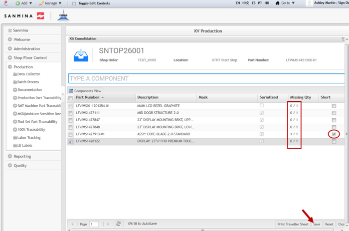
7. This process zeros out the Missing Quantity, thus consolidating all the components in the kit.
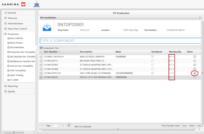
8. If there are missing components, mark the item as short by selecting the Short check box in the far right column.
Figure 19: Consolidated with Short Items
9. After consolidating all of the components, select Save to confirm.
10. Select Close to return to the Kit Browser main page.
Consolidation Recall
Consolidation Recall removes the consolidation link between a kit’s components and its Top Level serial number. A consolidation recall would be necessary for a Work Order cancellation or a decrease in quantity.
1. To perform a consolidation recall in the Kit Browser portlet, select a Shop Order from the list that has been consolidated and then select Consolidation Recall.
Figure 20: Consolidation Recall
2. The Consolidation Recall form displays. Select a Top Level serial and then select OK.
Figure 21: Top Level Serial
3. A confirmation pop-up displays. Select Yes to continue.
4. The Consolidation Recall Result pop-up displays with the Serial Number, Part Number, and Component information that has been recalled.
Figure 22: Consolidation Recall Result
Print/Reprint Traveler
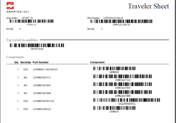
A traveler sheet provides a historical record of the items in a kit. The Shop Order, Part Number, quantity, Top Level Assembly, and all components are provided by the traveler.
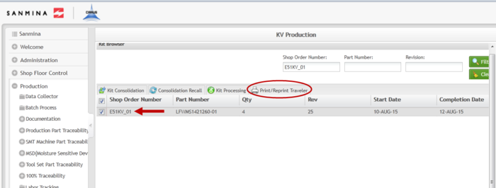
1. To print a traveler, select the Shop Order from the Shop Order Number list and then select Print/Reprint Traveler.
Figure 23: Print/Reprint Traveler
2. The One Traveler Per Unit:: form displays. Select the Top Level Assembly serial number and then select Print.
Figure 24: Top Level Assembly
3. The traveler will prompt to be opened with an external program. Select the program with which to open the file and then select OK.
4. The traveler will open in the external program for the user to print.
Figure 25: Traveler Sheet
Kit Processing
Kit Processing allows the user to perform Consolidation, Integration, Inspection, and Repair without having to navigate to the Kit Browser portlet to search for the correct Shop Order. If the Top Level Assembly is available for the Shop Order, it can be entered into the Serial Number field. The kit will display in the proper step in the kitting process and the user can complete the kit from the Kit Processing portlet.
Consolidation
The first step in the kitting process is Consolidation. This process consolidates all of the components in a kit. Once a kit is provided to the floor by a warehouse, all of its components must be consolidated to ensure there are no missing units.
NOTE: Best Practice- Prior to Consolidation, the Assembly Tables for all Serialized Components must be configured with Part Number masks.
1. To consolidate a kit, enter the Top Level Assembly into the field provided.
2. The Kit Processing portlet displays in the Kit Consolidation step.
3. All associated Part Numbers are listed for consolidation.
Figure 26: Kit Processing- Consolidation
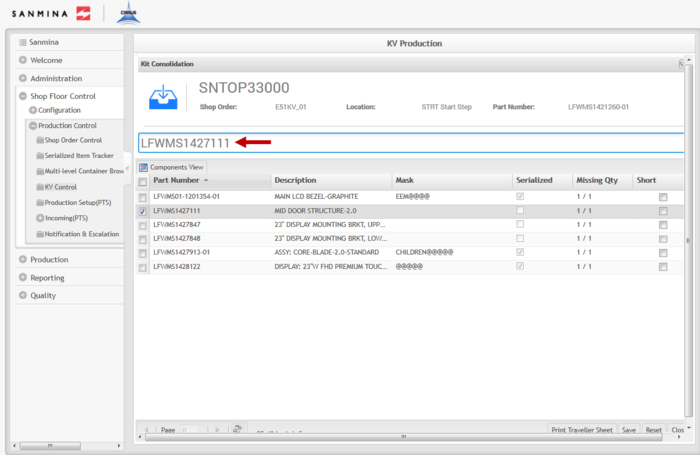
4. To consolidate the components, select each part number and then enter or scan the Part Number (for Non-Serialized components) or the serial that fits the mask (for Serialized components).
Figure 27: Consolidation
5. This process zeros out the Missing Quantity, thus consolidating all the components in the kit.
6. If there are missing components, mark the item as short by selecting the Short check box in the far right column.
Figure 28: Consolidated with Short Items
7. After consolidating all of the components, select Save to confirm.
8. "The record has been successfully saved" displays.
Integration
The second step in the kitting process is Integration. Integration is responsible for the assembly of the previously consolidated components.
1. To integrate a kit, enter the Top Level Assembly into the field provided
2. The Kit Processing portlet displays in the Integration step.
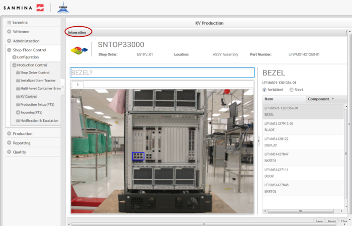
Figure 29: Integration
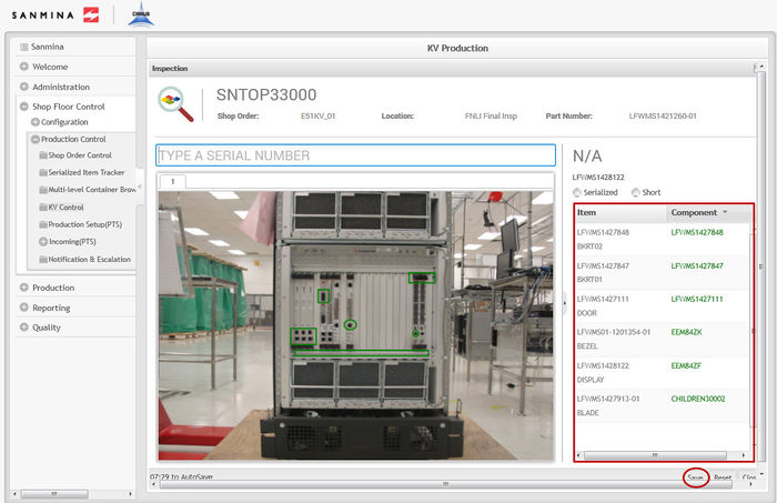
3. To integrate the components, select each item in the Item list and scan/enter the previously consolidated part number for non-serialized components or the serial that complies with the mask for serialized components.
NOTE: For non-serialized components with reference designators, the user will have to enter/scan the part number as many times as there are reference designators.
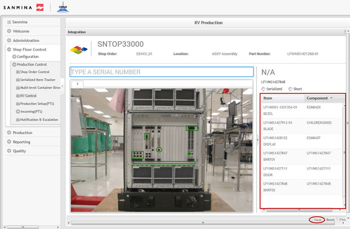
4. For short items, enter a serial that complies with the mask to integrate the component.
Figure 30: Integrated Kit
5. Once all items have been integrated, select Save to confirm.
6. "The record has been successfully saved" displays.
Inspection
The third step in the kitting process is Inspection. This step verifies that all previously integrated components are in the correct physical location.
1. To inspect a kit, enter the Top Level Assembly into the field provided
2. The Kit Processing portlet displays in the Inspection step.
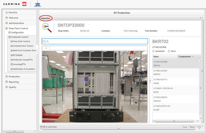
Figure 31: Inspection
3. To inspect the components, select each item in the Item list and scan/enter the previously consolidated part number for non-serialized components or the serial that complies with the mask for serialized components.
NOTE: For non-serialized components with reference designators, the user will have to enter/scan the part number as many times as there are reference designators.
Figure 32: Inspected Kit
4. Once all items have been inspected, select Save to confirm.
5. "The record has been successfully saved" displays.
NOTE: If there are failed components in a kit, they will display in red when entered/scanned and the kit will be sent to Repair when saved.
Repair
The fourth step in the kitting process is Repair. Repair allows for the repairing or replacing of failed components in the kit.
1. To repair a kit, enter the Top Level Assembly into the field provided
2. The Kit Processing portlet displays in the Repair step.
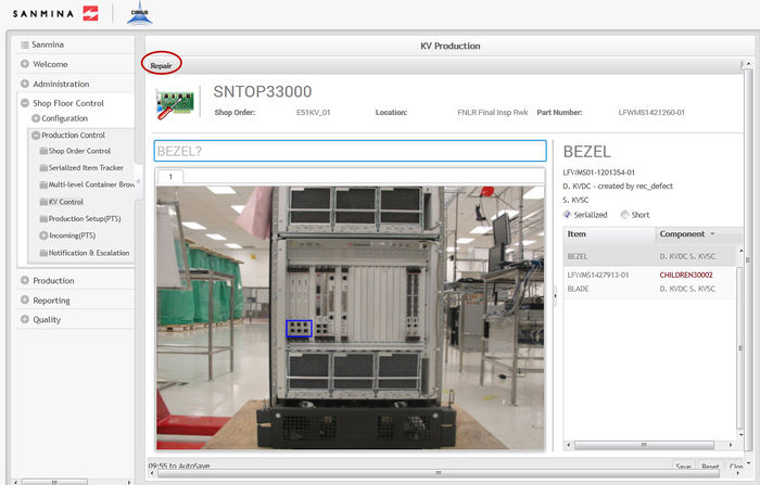
3. Only the components that have failed during the inspection step will display in the repair step.
Figure 33: Repair
4. To repair the components, select each item in the Item list and scan/enter the correct serial or part number that is displayed in the Component list.
5. Once all items have been repaired, select Save to confirm. This sends the kit back to the inspection step.
6. Complete the Inspection step again after repairing the failed items.
7. Once all items have been successfully inspected, the kit is complete and will no longer display in the Kit Processing portlet.
Document Revision History
| Date | Author | Title | Version | Change Reference |
| 09/04/15 | Ashley Martin | Technical Writer | v 1.0 | This is the first revision of the Kit Verify User Guide. |
