Difference between revisions of "Configuration"
| Line 1: | Line 1: | ||
| + | = Introduction<br> = | ||
| + | |||
| + | The Shop Floor Data Collection System (SFDC) communicates interactively with the Customer Order Processing System (COPS), and Statistical Process Control/Statistical Quality Control (SPC/SQC). The Manufacturing Data System (MDS) makes the communication between these systems possible. | ||
| + | |||
| + | <br>SFDC provides real-time information used by SPC/SQC and MESWeb to create quality control reports. The data configuration for SFDC PC is handled within the Manufacturing Data System (MDS), which is a complete factory automation system. The SFDC System uses barcode scanning, both manual and automated, to monitor and control a single product line or an entire plant. SFDC Configuration collects data, provides analysis, maintains unit histories, and controls product movement on the manufacturing floor. | ||
| + | |||
| + | <br>The system provides Access Control between the modules of the application, including the functionalities of each screen. The current version has an SFDC Configuration screen which provides access to all screens and its functionalities (view, add, edit, delete, print and generate output file), and a View-Only mode screen which only supports view, print and output to file; to support these screen modes, the MDS user or group of users have specific profiles, which provides specific access to MDS screens and functionalities. <br> | ||
| + | |||
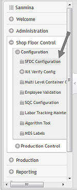
== SFDC Configuration == | == SFDC Configuration == | ||
| Line 13: | Line 21: | ||
*Any/all reports printed from jMDS modules will print to the default printer for the workstation. | *Any/all reports printed from jMDS modules will print to the default printer for the workstation. | ||
| − | <br> | + | <br> |
| − | === Misc. Config.<br> === | + | |
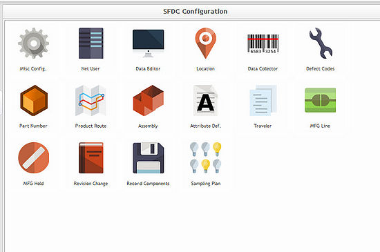
| + | === Misc. Config. [[Image:2014-01-28 8-48-10.jpg]]<br> === | ||
| + | |||
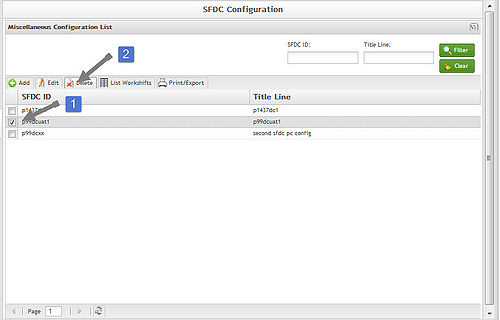
| + | This icon provides access to manage Miscellaneous Configurations, such as Net UserID, Line, Title Line, Screen Update Interval, Inactivity Days, SOMS Site ID, and Work Shift configuration. <br> | ||
==== Add ==== | ==== Add ==== | ||
| + | |||
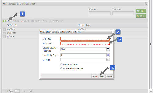
| + | To add a Miscellaneous Configuration, select the '''Add '''button located at the top left of the screen. A Miscellaneous Configuration form will pop-up. The '''SFDC ID''' and the '''Title Line''' are mandatory fields. '''Screen Update Interval''', '''Inactivity Days''', and '''Site ID''' are available to manipulate. Located at the bottom of the form boxes titled '''Update All Site ID''' and'''Download New Multipass'''. Both boxes are available to be selected. When all necessary information is entered, select the'''Save '''button.<br> | ||
[[Image:2014-01-27 15-56-39.jpg|center|500px|2014-01-27 15-56-39.jpg]] | [[Image:2014-01-27 15-56-39.jpg|center|500px|2014-01-27 15-56-39.jpg]] | ||
| − | + | '''SFDC ID''' – This is a unique network ID to identify the SFDC PC to the network. Each Net UserID must be unique in the same database. Usually this is the the same name as the Line, without a description. i.e. p99dc1<br> '''Title Line''' – A brief description of the Line. i.e. Plant 99 PCBA<br> '''Screen Update Interval '''– The time interval used between updates to the SFDC PC display. This value is normally set to 300.<br> '''Inactivity Days''' – The number of calendar days a unit may remain at a location before it is listed as inactive on the SFDC PC Serial Number Display.<br> '''Site Id''' – SOMS Site ID i.e. E99 | |
| − | + | '''Update All Site Id-'''<br> '''Download New Multipass''' – Check box to flag the configuration when using Multipass functionality for SOMS. <br> | |
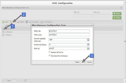
| − | ==== | + | ==== Edit ==== |
| − | + | [[Image:2014-01-27 16-01-17.jpg|center|500px|2014-01-27 16-01-17.jpg]] | |
| − | + | ==== Delete ==== | |
| − | ==== | + | ==== [[Image:2014-01-27 16-04-02.jpg|center|500px|2014-01-27 16-04-02.jpg]]List Workshifts ==== |
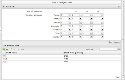
| − | [[Image:2014-01- | + | [[Image:2014-01-27 16-06-14.jpg|center|500px|2014-01-27 16-06-14.jpg]] |
| + | |||
| + | ==== Print/Export ==== | ||
| + | |||
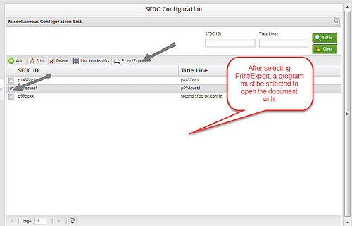
| + | [[Image:2014-01-27 16-08-38.jpg|center|500px|2014-01-27 16-08-38.jpg]] | ||
=== Net User<br> === | === Net User<br> === | ||
| Line 66: | Line 83: | ||
<br> | <br> | ||
| − | <br> | + | <br> |
== Kit Verify Configuration == | == Kit Verify Configuration == | ||
| Line 207: | Line 224: | ||
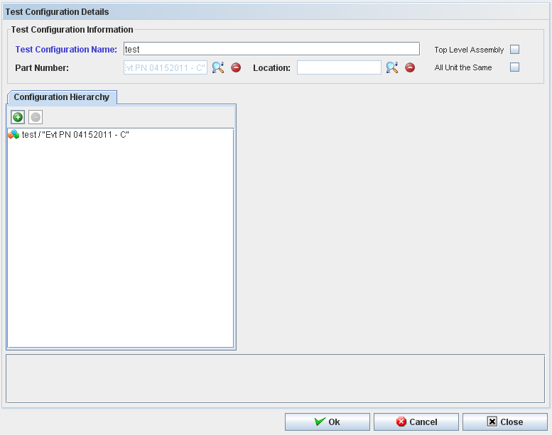
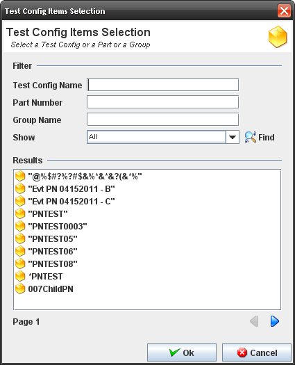
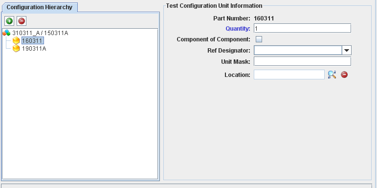
=== Test Configuration === | === Test Configuration === | ||
| + | |||
'''Figure 25: Test Configuration window''' | '''Figure 25: Test Configuration window''' | ||
| Line 554: | Line 572: | ||
'''Note''': Only top assembly serial numbers in status >=20 which have a test configuration created for the main part number must be displayed. The paginator buttons (previous and next) are displayed and 10 serial numbers are displayed per page. | '''Note''': Only top assembly serial numbers in status >=20 which have a test configuration created for the main part number must be displayed. The paginator buttons (previous and next) are displayed and 10 serial numbers are displayed per page. | ||
| − | <br> | + | <br> |
==== Showing Integration Information ==== | ==== Showing Integration Information ==== | ||
| Line 572: | Line 590: | ||
#The message "Are you sure you want to create a new component integration?" is displayed. | #The message "Are you sure you want to create a new component integration?" is displayed. | ||
| − | === Alert Distribution === | + | === Alert Distribution === |
| − | |||
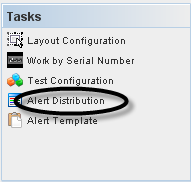
| + | To access the Alert Distribution functionality, from Tasks panel, click on '''Alert Distribution'''. | ||
| − | '''Figure 53: Shop Order List''' | + | <br> '''Figure 53: Shop Order List''' |
| − | [[ | + | [[Image:KV53.png]] |
| + | <br> The alert distribution list should be like a profile. We can select the user for each program and these users will receive an email alert base on xml template. | ||
| − | The | + | <br> The Alert Distribution list displays: |
| + | <br> '''Figure 54: Alert Distribution''' | ||
| − | + | [[Image:KV54.png|800px|KV54.png]] | |
| + | <br> From this screen, the user is able to add, edit, copy or delete alerts distribution. See the next topics for more information. | ||
| − | + | <br> | |
| − | + | ==== Adding Alert Distribution ==== | |
| + | '''Figure 55: Adding Alert Distribution''' | ||
| − | + | [[Image:KV55.png|800px|KV55.png]] | |
| + | The Add Alert Distribution window displays: | ||
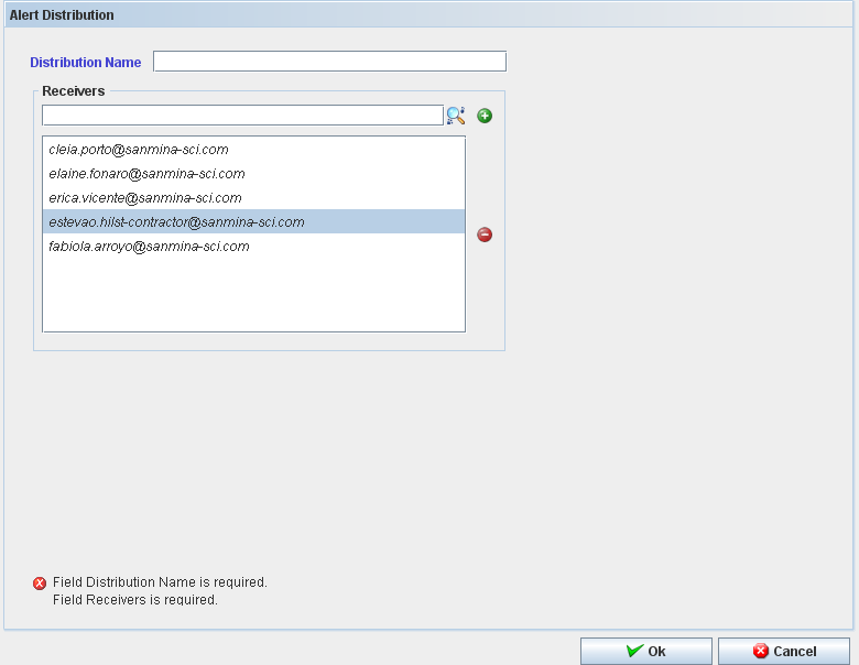
| − | + | <br> '''Figure 56: Add Alert Distribution''' | |
| − | '''Figure | ||
| − | [[ | + | [[Image:KV56.png]] |
| − | + | <br> To add an Alert Distribution, follow the steps bellow: | |
| + | #In Task Panel click in "'''Add Alert Distribution"''' option; | ||
| + | #Fill the mandatory fields (Distribution Name and Receivers); | ||
| + | #Click in "'''Ok'''" button; | ||
| + | #Confirm the Alert Distribution creation. | ||
| − | + | The "Alert Distribution" window closes and the "Alert" is displayed with the recorded "Alert" in the table. | |
| − | + | The user can search for receivers. Click on “+” to add or “-” to delete. | |
| + | ==== Editing Alert Distribution ==== | ||
| − | + | '''Figure 57: Editing Alert Distribution.''' | |
| − | + | [[Image:KV57.png|800px|KV57.png]] | |
| − | |||
| − | |||
| − | |||
| − | + | <br> Follow the steps bellow to edit an alert distribution: | |
| − | + | <br> | |
| − | + | #On the Alert Distribution list, select an existing Alert; | |
| − | ''' | + | #Click the Edit icon; The Alert Distribution screen displays. It is the same for Add Distribution alert. |
| + | #Change the mandatory fields; | ||
| + | #Click "'''OK'''" button | ||
| + | #Confirm the Edit. | ||
| − | + | ==== Copying Alert Distribution ==== | |
| + | '''Figure 58: Copying Alert Distribution''' | ||
| − | + | [[Image:KV58.png|800px|KV58.png]] | |
| + | <br> The copy feature allows the user to copy alert information. Follow the steps bellow: | ||
| − | + | <br> | |
| − | |||
| − | |||
| − | |||
| − | |||
| − | + | #On the Alert Distribution List, select an existing Alert; | |
| − | ''' | + | #Click the Copy Icon; |
| + | #Change the mandatory fields; | ||
| + | #Click "'''OK'''" button. | ||
| − | + | ==== Deleting Alert Distribution ==== | |
| + | '''Figure 59: Deleting Alert Distribution''' | ||
| − | + | [[Image:KV59.png|800px|KV59.png]] | |
| + | <br> Follow the steps bellow to delete an Alert: | ||
| − | + | <br> | |
| − | |||
| − | |||
| − | |||
| − | + | #On the Alert Distribution List, select an existing Alert; | |
| − | ''' | + | #Click the Delete icon; |
| + | #Click "'''OK'''" button. | ||
| + | #A confirmation box displays. | ||
| + | #The Alert is deleted. | ||
| − | + | == Multi-Level Container Configuration == | |
| − | |||
| − | |||
| − | |||
| − | |||
| − | |||
| − | |||
| − | |||
| − | |||
| − | |||
| − | |||
| − | |||
This chapter describes how the user manages the Multi-Level Containerization MDS Module. It details all functionalities and actions that can be performed by users. | This chapter describes how the user manages the Multi-Level Containerization MDS Module. It details all functionalities and actions that can be performed by users. | ||
| + | <br> '''GENERAL NOTES:''' | ||
| − | + | <br> | |
| + | *Most error and informational messages are displayed in a dialog box. Click '''OK''' or press '''Enter '''to dismiss the dialog window. '''Yes''' or'''No''' buttons may also be provided to answer questions presented by the message dialog window. | ||
| + | *The user Profile defines what the user can access. | ||
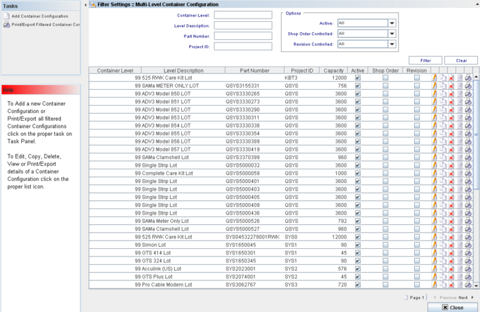
| − | + | '''Figure 3: Multi-Level Container Configuration''' | |
| − | |||
| − | + | [[Image:MLC03.png|700px|MLC03.png]] | |
| − | + | The user is able to perform actions like create, print/export filtered results, edit, copy, delete, view or print/export containers configuration. | |
| − | The | + | <br> The next topics will describe all available Container Configuration functionalities. |
| + | === Container List === | ||
| − | The | + | The '''Container List''' displays all container levels and allows performing the following actions: |
| − | + | #'''Filter''' '''Data''' | |
| − | + | #'''Edit a Container Configuration''' | |
| + | #'''Copy a Container Configuration''' | ||
| + | #'''View a Container Configuration''' | ||
| + | #'''Delete a Container Configuration''' | ||
| + | #'''Print/Export details of a Container Configuration'''. | ||
| − | + | Note that it is possible to execute two actions from the Task Panel: | |
| − | |||
| − | |||
| − | |||
| − | |||
| − | |||
| − | + | <br> | |
| + | #'''Add a new Container Configuration''' | ||
| + | #'''Print/Export all Filtered Container Configurations''' | ||
| − | + | === Filter Settings === | |
| − | |||
| − | |||
To perform searches, there are four available fields: | To perform searches, there are four available fields: | ||
| − | '''Container Level''': Predefined container levels are: “99 LOT”, “100 BOX”, “110 SKID” and “120 PALLET”; levels 101-999 are Multi-Level Containers and are handled only by MDS Client | + | '''Container Level''': Predefined container levels are: “99 LOT”, “100 BOX”, “110 SKID” and “120 PALLET”; levels 101-999 are Multi-Level Containers and are handled only by MDS Client. |
| − | |||
| − | |||
| − | ''' | + | '''Level Description:''' The default description for the level. |
| − | ''' | + | '''Part Number: '''A number which serves to uniquely identify a part (product). |
| + | '''Project ID:''' The project identification number. | ||
| − | Also, the user can select additional options from the Options section: | + | <br> Also, the user can select additional options from the Options section: |
'''Active''' (All, No, Yes): NO implies inactive for containerization. Default=YES; | '''Active''' (All, No, Yes): NO implies inactive for containerization. Default=YES; | ||
| − | '''Shop Order controlled''' (All, No, Yes): YES allows only units from a single shop order to be containerized together. Default=NO; | + | '''Shop Order controlled''' (All, No, Yes): YES allows only units from a single shop order to be containerized together. Default=NO; |
| − | '''Revision Controlled''' (All, No, Yes): YES means only one revision can be containerized together. Please correct and check the default value. | + | '''Revision Controlled''' (All, No, Yes): YES means only one revision can be containerized together. Please correct and check the default value. |
| + | <br> Enter the information or combination of information and click on '''Find'''. | ||
| − | + | <br> '''Figure 4: Filter Settings''' | |
| + | [[Image:MLC04.png|700px|MLC04.png]] | ||
| − | ''' | + | <br> To clear the fields’ contents, click on '''Clear''' button to start a new filter. |
| − | + | === Edit Container Configuration === | |
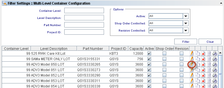
| + | To edit a container configuration, go to '''MDS Client > Multi-Level Containerization > Container Configuration> Container Configuration list''', select an existing Container Configuration and click on '''Edit''' Icon. | ||
| − | + | <br> '''Figure 5: Multi-Level Container Configuration - Edit''' | |
| − | + | [[Image:MLC05.png]] | |
| − | |||
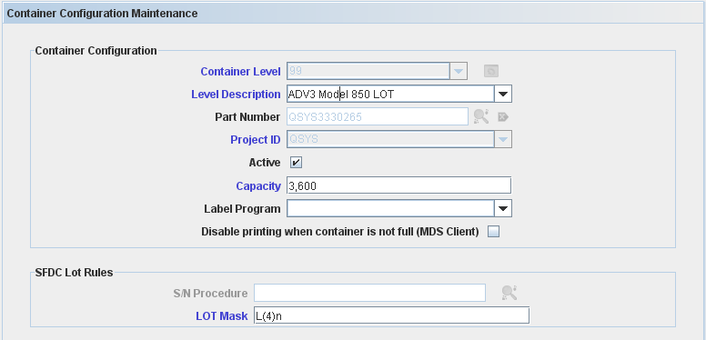
| + | <br> The Container Configuration Maintenance screen displays: | ||
| − | '''Figure | + | <br> '''Figure 6: Container Configuration Maintenance - Edit''' |
| − | [[ | + | [[Image:MLC06.png]] |
| + | <br> All the container configuration information is updated according to the updates applied and the container configuration is displayed in the container configuration's list. | ||
| − | + | <br> '''Container Level, Part Number '''and '''Project ID''' cannot be edited, as they are the keys of the record. | |
| + | <br> '''Note''': For more details about a field’s description, see the [#_5.1.2a_Create_Container Create Container Configuration] topic. | ||
| − | + | === Copy Container Configuration === | |
| − | + | To copy Container Configuration definitions, go to '''Container Configuration> Container Configuration list''', select an existing Container Configuration and click on the '''Copy''' icon. | |
| + | <br> The Container Configuration Maintenance window is displayed: | ||
| − | + | <br> '''Figure 7: Container Configuration Maintenance - Copy''' | |
| + | [[Image:MLC07.png]] | ||
| − | + | <br> Change the necessary information and click on the "'''Ok'''" button. The new Container configuration created is displayed on Container Configuration List. | |
| + | <br> | ||
| − | + | === Delete Container Configuration === | |
| − | + | To delete a container configuration, go to '''Multi-Level Containerization > Container Configuration> Container Configuration list''', select an existing Container Configuration and click on '''Delete''' Icon. | |
| − | To | ||
| + | <br> '''Figure 8: Multi-Level Container Configuration - Delete''' | ||
| − | + | [[Image:MLC08.png]] | |
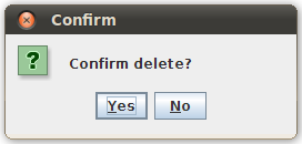
| + | <br> A confirmation message displays. Click on '''Yes '''to confirm the deletion or '''No''' to cancel. The Container Configuration will be deleted from the containers list. | ||
| − | + | === View Container Configuration === | |
| − | + | To view the container information, go to '''Multi-Level Containerization > Container Configuration> Container Configuration list''', select an existing Container Configuration and click on the '''view''' Icon. | |
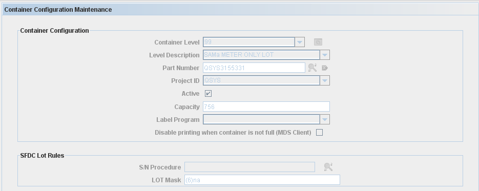
| + | The container configuration maintenance window displays: | ||
| − | + | <br> '''Figure 9: View Container Configuration Window''' | |
| + | [[Image:MLC09.png]] | ||
| − | + | '''Note''': all the fields are read only. | |
| − | |||
| + | === Print/Export Container Configuration === | ||
| − | ''' | + | 1) To print/export containers, go to '''Multi-Level Containerization > Container Configuration> Container Configuration list''', select an existing Container Configuration and click on the '''Print/Export Container Configuration''' Icon. |
| − | + | A report is generated. In the viewer screen, click on "'''Save'''" or “'''Print'''” button to save or print the report result. | |
| + | === Container Task Panel === | ||
| − | + | From the '''Task Panel''' the user is able to create a new container configuration and print/export all filtered container configuration created. | |
| − | + | <br> | |
| − | |||
| − | + | === Create Container Configuration: Level 99 (LOT) /Level 100 (Container) === | |
| + | There are different configurations for Containers Level 99 (LOT) and level 100 (Container). See bellow the differences between them. | ||
| − | ''' | + | <br> '''<nowiki>** Container Level = 99: </nowiki>Configuration ''' |
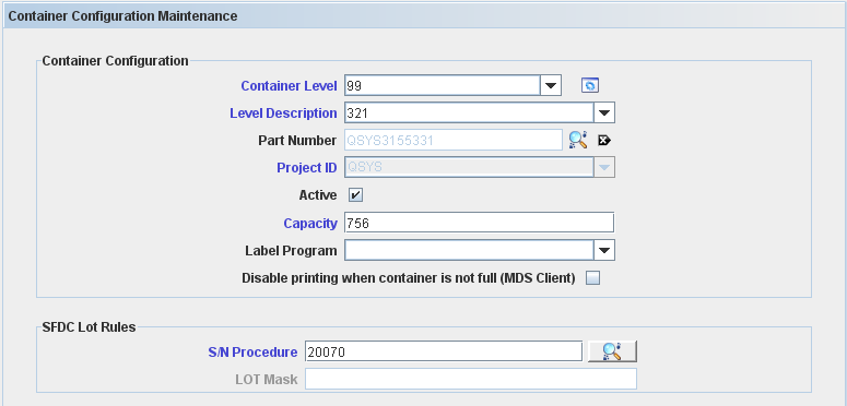
| − | + | <br> To create a container configuration, go to '''Multi-Level Containerization > Container Configuration > Task Panel '''and click on '''Add Container Configuration'''. | |
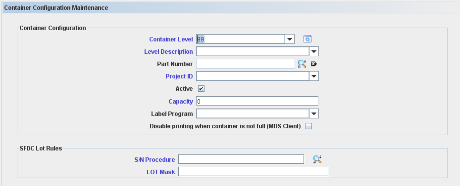
| − | + | The Container Configuration Maintenance screen is displayed: | |
| − | + | <br> '''Figure 10: Container Configuration Maintenance''' | |
| − | |||
| − | + | [[Image:MLC010.png]] | |
| − | + | <br> Container Configuration fields description: | |
| − | |||
| − | |||
| − | |||
| − | |||
| − | |||
| − | |||
| − | |||
| − | |||
| − | |||
| − | |||
| − | |||
| − | |||
| − | |||
| − | |||
| − | |||
| − | |||
| − | |||
| − | |||
| − | |||
| − | |||
| − | Container Configuration fields description: | ||
'''Container Level''': defines the container level (99 to 999) – default is Empty. For this topic, the level used is 99(LOT). The default Container Levels, 99 - LOT, 100 - CONTAINER, 110 - SKID and 120 - PALLET cannot be edited or deleted, it’s created automatically by the application. | '''Container Level''': defines the container level (99 to 999) – default is Empty. For this topic, the level used is 99(LOT). The default Container Levels, 99 - LOT, 100 - CONTAINER, 110 - SKID and 120 - PALLET cannot be edited or deleted, it’s created automatically by the application. | ||
| + | <br> '''SFDC Lot Rules:''' | ||
| − | ''' | + | *'''S/N Procedure: '''not used when Serial Mask is specified. The field can contain either (i) a predefined program filename or (ii) an algorithm number, if the algorithm was defined using the Algorithm Tool – default Empty; |
| + | *'''Lot Mask''': not used when Serial Algorithm Procedure is specified. Up to 30 characters in length. The mask of the serial number for the container or lot. Using a serial mask, container serialization schemes can be different per part number – default Empty; | ||
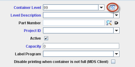
| − | + | To manage the container levels click on Manage icon: | |
| − | |||
| − | + | '''Figure 11: Container configuration Maintenance''' | |
| − | + | [[Image:MLC011.png]] | |
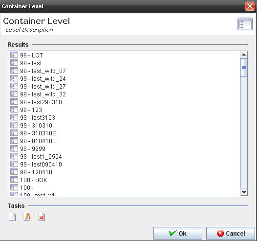
| − | + | The Manage Level screen is displayed: | |
| − | + | <br> '''Figure 12: Container Level Maintenance''' | |
| + | [[Image:MLC012.png]] | ||
| − | ''' | + | The user is able to '''Add''', '''Edit''' or '''Delete''' container levels. |
| − | + | ==== Create a new container level ==== | |
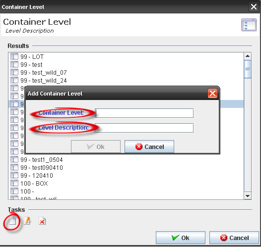
| − | + | To add a container level, click on the '''Add''' icon in the bottom of the window. The '''Add Container Level''' window displays. | |
| − | + | <br> '''Figure 13: Container Level - Add''' | |
| − | |||
| + | [[Image:MLC013.png]] | ||
| − | ''' | + | Enter the "'''Container Level'''" with a value between 99 to 999 and the "'''Level Description'''" with a value that does not exist in the database. Click on '''OK''' to finish. |
| − | + | The new container level will be displayed in the containers level list and the user will be able to select it when creating/editing a container configuration. | |
| − | + | <br> | |
| − | + | ==== Edit/delete a container level ==== | |
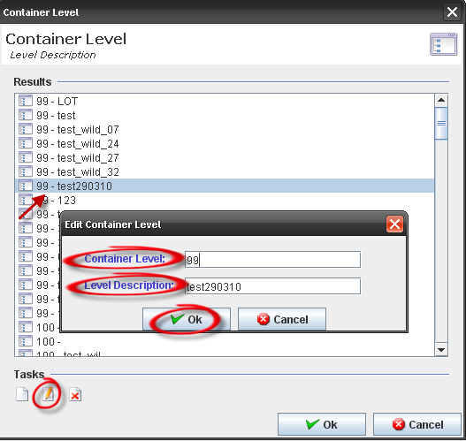
| + | '''Edit/delete container level''': (maintenance button) can be performed at any time except for a default value or a container definition that already exists for that level; otherwise, if there are no definitions, editing or deleting a container level is allowed. '''Type 99 (LOT) cannot be edited'''. Also, all types without a container configuration associated can be deleted. If a definition already exists, then the container level cannot be modified. | ||
| − | + | <br> '''Figure 14: Container Level – Edit ''' | |
| − | '''Edit | ||
| + | [[Image:MLC014.png]] | ||
| − | '''Figure | + | <br> '''Figure 15: Container Level - Delete''' |
| − | [[ | + | [[Image:MLC015.png]] |
| + | <br> '''<nowiki>** Container Level = 100: </nowiki>'''SFDC Container Rules section | ||
| − | + | New configuration was added for level 100 and will run just in the MDS Client. Just configuration with algorithm type = Container will run in the SFDC. | |
| − | + | <br> It supports the following options: | |
| + | *Revision Controlled; | ||
| + | *Shop Order Controlled; | ||
| + | *Auto Close; | ||
| + | *Dimensions (MDS Client only); | ||
| + | *Shipping Level | ||
| + | *Multi Part | ||
| + | *S/N Procedure | ||
| + | *Container Mask | ||
| − | ''' | + | '''General Rules:''' |
| − | + | After entering all mandatory fields, click on the "'''OK'''" button and confirm the configuration creation. The container configuration list is updated with the new container configuration, with the inserted data. | |
| + | It is necessary to use the same "Level" for all records with the same "Description". For example, if you create a level 120 and say that the name is "Overpack Box", then any other record which is added later that has the description "Overpack Box" needs to be level 120. | ||
| − | + | '''Note''': The application cannot show obsolete part numbers for selection during the creation of a container configuration. | |
| − | + | <br> | |
| − | |||
| − | |||
| − | |||
| − | |||
| − | |||
| − | |||
| − | |||
| − | + | === Create Multi-Level Configuration Containers: Type > 100 === | |
| − | + | To create a new Container Configuration, click on '''Add Container Configuration''' button in the task panel. | |
| − | + | <br> '''Figure 16: Add Container Configuration''' | |
| − | + | [[Image:MLC016.png|700px|MLC016.png]] | |
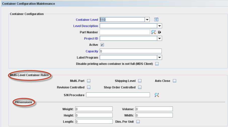
| + | <br> The Container Configuration Maintenance window is displayed: | ||
| − | + | <br> '''Figure 17: Multi-Level Container Configuration Maintenance''' | |
| − | |||
| + | [[Image:MLC017.png]] | ||
| − | ''' | + | <br> The following fields are displayed just for containers >100: '''Container Level, Level Description, Part Number''', '''Project ID, Active, Capacity''', '''Label Program '''and'''Disable printing when container is not full''' (checking this option, the container configuration will print only when the container is full). |
| − | + | <br> The following check boxes are displayed as Multi Level Container Rule: | |
| + | *'''Revision Controlled''': '''Revision Controlled''' (All, No, Yes): YES means only one revision can be containerized together. Please correct and check the default value. | ||
| + | *'''Shop Order Controlled''': Yes / No. Yes allows only units from a single shop order to be containerized together – default No; | ||
| + | *'''Shipping Level''': Yes / No. Yes defines that a specific container is the Shipping level of containerization – default No; | ||
| + | *'''Auto Close''': Yes / No – default No; | ||
| + | *'''S/N Procedure''': Show all “COPS Container” algorithms created in Algorithm Tool – default Empty. Not used when Serial Mask is specified. The field can contain either (i) a predefined program filename or (ii) an algorithm number, if the algorithm was defined using the Algorithm Tool – default Empty; | ||
| + | *'''Multi Part:''' Allow multiple part number in a container. It is possible to add elements from another part number, but it must have the same Project Id. | ||
| − | + | In Addition, the user can define the Container dimension filling the weight (kg), height (m), length (m), volume (m3) and width (m). Selecting the Dimension per Unit flag, it is possible to fill for each configuration container. If the dimension is in different measure, the data will be converted. | |
| + | <br> | ||
| − | + | === Print/Export All Filtered Container Configuration === | |
| − | |||
| − | |||
| − | |||
| − | |||
| − | |||
| − | |||
| − | |||
| − | |||
| − | |||
| − | |||
| − | |||
| − | |||
| − | |||
| − | |||
| − | |||
| − | |||
| − | |||
| + | To '''Print/Export''' all Filtered Container Configurations, click on '''Print/Export Container Configurations''' button in the tasks panel. | ||
| − | + | A report is generated: | |
| − | |||
| − | + | '''Figure 18: Print All Filtered Container Configuration''' | |
| − | + | [[Image:MLC018.png|700px|MLC018.png]] | |
| − | + | <br> The user can perform some actions (print, save, fit page…) by clicking on the buttons in the top of the report. | |
| − | |||
| − | |||
| − | The user can perform some actions (print, save, fit page…) by clicking on the buttons in the top of the report. | ||
== Employee Validation == | == Employee Validation == | ||
| − | === <br>Employee Validation Setup === | + | === <br>Employee Validation Setup === |
'''This edition applies to MDS14-5 Application (Employee Validation Module) and all subsequent releases and modifications until otherwise indicated in new revisions.''' | '''This edition applies to MDS14-5 Application (Employee Validation Module) and all subsequent releases and modifications until otherwise indicated in new revisions.''' | ||
| Line 957: | Line 960: | ||
'''Figure 1: MDS Modules''' | '''Figure 1: MDS Modules''' | ||
| − | [[Image:SOP-5-I-MDS0023-C-MDS Employee Validation WIKI 01.png|frame|none | + | [[Image:SOP-5-I-MDS0023-C-MDS Employee Validation WIKI 01.png|frame|none]] |
The Employee Validation Maintenance page is displayed as follow: | The Employee Validation Maintenance page is displayed as follow: | ||
| Line 963: | Line 966: | ||
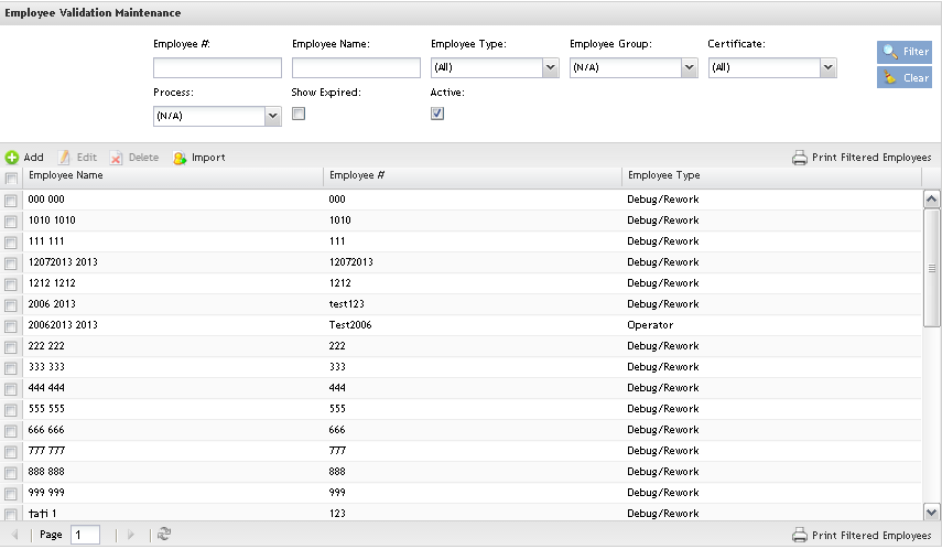
'''Figure 2: Employee Validation Maintenance''' | '''Figure 2: Employee Validation Maintenance''' | ||
| − | [[Image:SOP-5-I-MDS0023-C-MDS Employee Validation WIKI 02.png|frame|none | + | [[Image:SOP-5-I-MDS0023-C-MDS Employee Validation WIKI 02.png|frame|none]] |
Employee Validation is composed by sub-modules and these work instructions will help users to understand each one. | Employee Validation is composed by sub-modules and these work instructions will help users to understand each one. | ||
| Line 973: | Line 976: | ||
*'''Process Group Maintenance''': | *'''Process Group Maintenance''': | ||
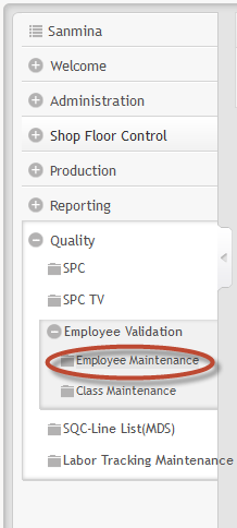
| − | === Employee Maintenance === | + | === Employee Maintenance === |
To access Employee Maintenance, click on '''Employee Maintenance''' in the employee validation main page. | To access Employee Maintenance, click on '''Employee Maintenance''' in the employee validation main page. | ||
| Line 979: | Line 982: | ||
The first step in setting up Employee Validation is to define all the Employees in the Employee Maintenance module. | The first step in setting up Employee Validation is to define all the Employees in the Employee Maintenance module. | ||
| − | ==== Listing employees ==== | + | ==== Listing employees ==== |
The Employee List displays all employees<nowiki>’</nowiki> name, type and number and allows filtering data by entering data in the available field, edit employees by clicking on Edit icon and delete employees by clicking on Delete icon; | The Employee List displays all employees<nowiki>’</nowiki> name, type and number and allows filtering data by entering data in the available field, edit employees by clicking on Edit icon and delete employees by clicking on Delete icon; | ||
| Line 985: | Line 988: | ||
'''Figure 3: Employee Maintenance Page''' | '''Figure 3: Employee Maintenance Page''' | ||
| − | [[Image:SOP-5-I-MDS0023-C-MDS Employee Validation WIKI 03.png|frame|none | + | [[Image:SOP-5-I-MDS0023-C-MDS Employee Validation WIKI 03.png|frame|none]] |
This is the main Employee validation maintenance page and the users are able to perform searches, sort, add, edit, delete, import and print/export employees. | This is the main Employee validation maintenance page and the users are able to perform searches, sort, add, edit, delete, import and print/export employees. | ||
| − | ==== Performing Searches ==== | + | ==== Performing Searches ==== |
To perform searches, there are four available fields: '''Employee #, Employee Name, Employee Type, Employee Group, Certificate, Process and the Active/Show Expired flags'''. | To perform searches, there are four available fields: '''Employee #, Employee Name, Employee Type, Employee Group, Certificate, Process and the Active/Show Expired flags'''. | ||
| Line 997: | Line 1,000: | ||
'''Figure 4: List and Search Employees''' | '''Figure 4: List and Search Employees''' | ||
| − | [[Image:SOP-5-I-MDS0023-C-MDS Employee Validation WIKI 04.png|frame|none | + | [[Image:SOP-5-I-MDS0023-C-MDS Employee Validation WIKI 04.png|frame|none]] |
The search result is displayed in the Employee list. | The search result is displayed in the Employee list. | ||
| Line 1,003: | Line 1,006: | ||
'''Note''': It is possible to list only the active employees by checking the '''Active''' check box. | '''Note''': It is possible to list only the active employees by checking the '''Active''' check box. | ||
| − | ==== Adding Employee ==== | + | ==== Adding Employee ==== |
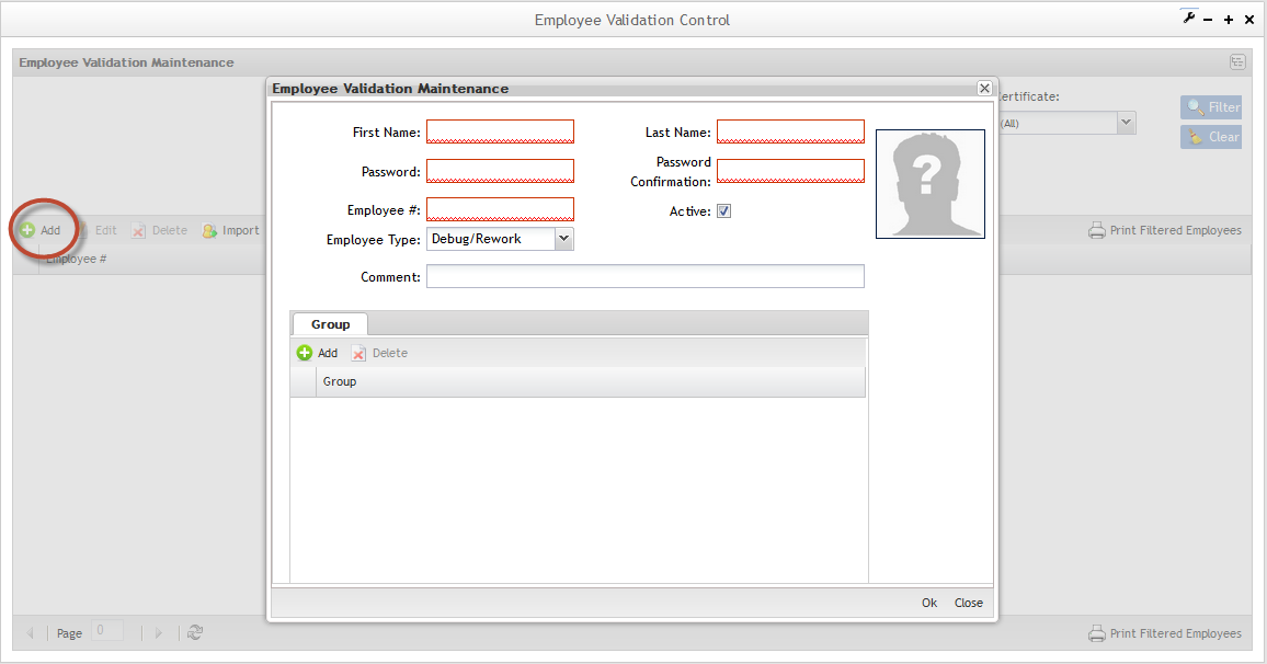
This functionality allows adding employees in the application. | This functionality allows adding employees in the application. | ||
| Line 1,015: | Line 1,018: | ||
'''Figure 5: Adding Employee''' | '''Figure 5: Adding Employee''' | ||
| − | [[Image:SOP-5-I-MDS0023-C-MDS Employee Validation WIKI 05.png|frame|none | + | [[Image:SOP-5-I-MDS0023-C-MDS Employee Validation WIKI 05.png|frame|none]] |
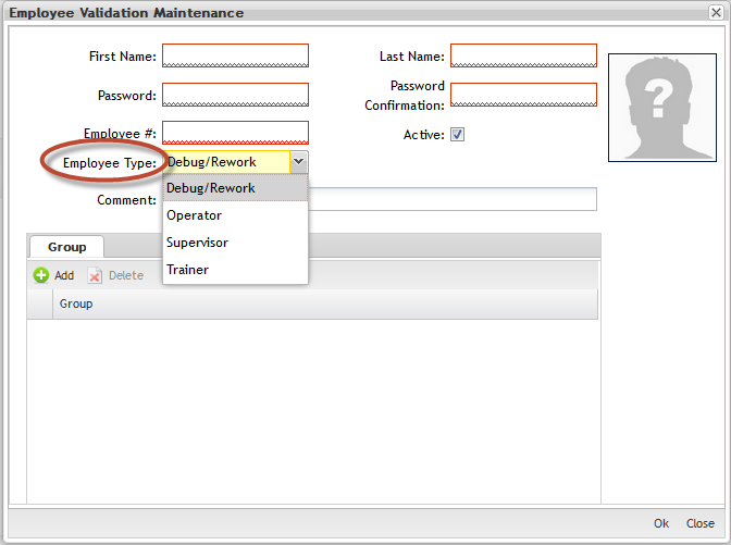
Fill in all mandatory fields (in red):'''"First Name"''', '''"Last Name"''','''"Password"''', '''"Password Confirmation"''', '''"Employee#"''', '''"Employee Type"''' (operator, supervisor or trainer). | Fill in all mandatory fields (in red):'''"First Name"''', '''"Last Name"''','''"Password"''', '''"Password Confirmation"''', '''"Employee#"''', '''"Employee Type"''' (operator, supervisor or trainer). | ||
| Line 1,027: | Line 1,030: | ||
'''Figure 6: Employee Validation - Employee Type''' | '''Figure 6: Employee Validation - Employee Type''' | ||
| − | [[Image:SOP-5-I-MDS0023-C-MDS Employee Validation WIKI 06.png|frame|none | + | [[Image:SOP-5-I-MDS0023-C-MDS Employee Validation WIKI 06.png|frame|none]] |
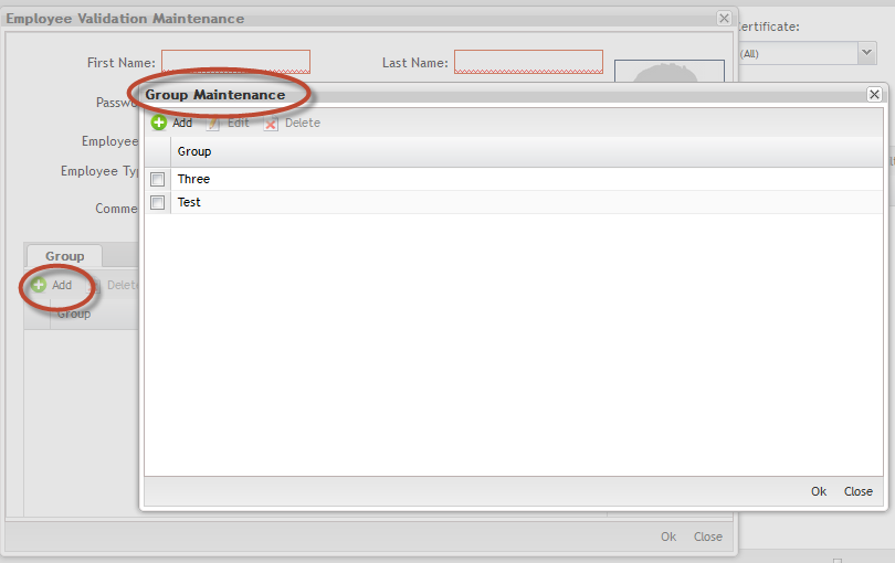
After Employee records have been created, each employee should be associated to at least one Group. | After Employee records have been created, each employee should be associated to at least one Group. | ||
| Line 1,039: | Line 1,042: | ||
'''Figure 7: Groups Maintenance''' | '''Figure 7: Groups Maintenance''' | ||
| − | <font color="#FF0000">[[Image:SOP-5-I-MDS0023-C-MDS Employee Validation WIKI 07.png|frame|none | + | <font color="#FF0000">[[Image:SOP-5-I-MDS0023-C-MDS Employee Validation WIKI 07.png|frame|none]] </font> |
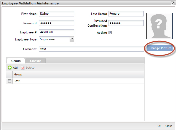
After insert the employee data, the user is able to upload the employee image, or if prefer, upload the image in the future using the '''Edit Employee''' button. | After insert the employee data, the user is able to upload the employee image, or if prefer, upload the image in the future using the '''Edit Employee''' button. | ||
| Line 1,045: | Line 1,048: | ||
'''Figure 8: Uploading Employee Image''' | '''Figure 8: Uploading Employee Image''' | ||
| − | [[Image:SOP-5-I-MDS0023-C-MDS Employee Validation WIKI 08.png|frame|none | + | [[Image:SOP-5-I-MDS0023-C-MDS Employee Validation WIKI 08.png|frame|none]] |
Click on '''Y'''es to continue the upload or '''No''' to abort. | Click on '''Y'''es to continue the upload or '''No''' to abort. | ||
| Line 1,051: | Line 1,054: | ||
Click on Change Picture to upload and save the image. | Click on Change Picture to upload and save the image. | ||
| − | ==== Importing Employees ==== | + | ==== Importing Employees ==== |
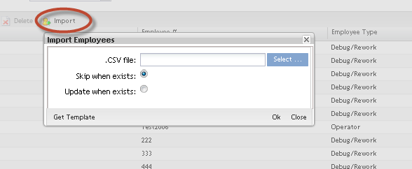
To Import Employees from a CSV file, click on '''Import'''. | To Import Employees from a CSV file, click on '''Import'''. | ||
| Line 1,057: | Line 1,060: | ||
'''Figure 9: Import Employees''' | '''Figure 9: Import Employees''' | ||
| − | [[Image:SOP-5-I-MDS0023-C-MDS Employee Validation WIKI 09.png|frame|none | + | [[Image:SOP-5-I-MDS0023-C-MDS Employee Validation WIKI 09.png|frame|none]] |
The Import employee is displayed. | The Import employee is displayed. | ||
| Line 1,092: | Line 1,095: | ||
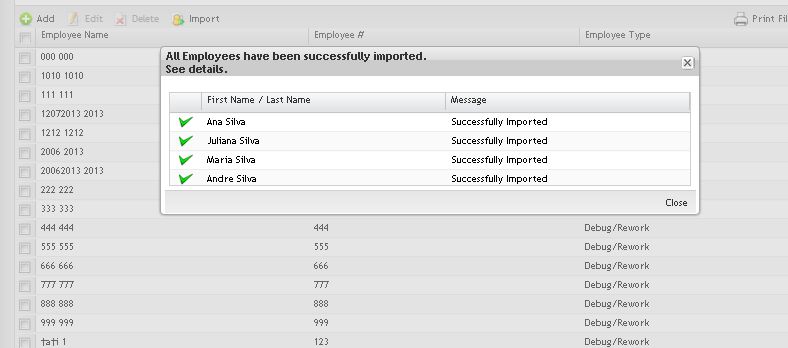
'''Figure 10: Import Employees''' | '''Figure 10: Import Employees''' | ||
| − | [[Image:SOP-5-I-MDS0023-C-MDS Employee Validation WIKI 10.png|frame|none | + | [[Image:SOP-5-I-MDS0023-C-MDS Employee Validation WIKI 10.png|frame|none]] |
*Click on "'''Close'''" button. | *Click on "'''Close'''" button. | ||
| Line 1,098: | Line 1,101: | ||
After the import process, a report is displayed with the employees successfully imported and with those who failed. | After the import process, a report is displayed with the employees successfully imported and with those who failed. | ||
| − | ==== Print Filtered Employees ==== | + | ==== Print Filtered Employees ==== |
To Print Filtered Employees list, click on '''Print Filtered Employees''' button. | To Print Filtered Employees list, click on '''Print Filtered Employees''' button. | ||
| Line 1,104: | Line 1,107: | ||
'''Figure 11: Exporting Employees''' | '''Figure 11: Exporting Employees''' | ||
| − | [[Image:SOP-5-I-MDS0023-C-MDS Employee Validation WIKI 11.png|frame|none | + | [[Image:SOP-5-I-MDS0023-C-MDS Employee Validation WIKI 11.png|frame|none]] |
A .pdf report is generated with classes, certificates and processes. The user can save it and print. | A .pdf report is generated with classes, certificates and processes. The user can save it and print. | ||
| − | ==== Editing Employees Information ==== | + | ==== Editing Employees Information ==== |
'''Figure 12: Editing Employee Information''' | '''Figure 12: Editing Employee Information''' | ||
| − | [[Image:SOP-5-I-MDS0023-C-MDS Employee Validation WIKI 12.png|frame|none | + | [[Image:SOP-5-I-MDS0023-C-MDS Employee Validation WIKI 12.png|frame|none]] |
It is possible to '''edit''' the employee information by selecting the employee and clicking on '''Edit''' button. | It is possible to '''edit''' the employee information by selecting the employee and clicking on '''Edit''' button. | ||
| Line 1,118: | Line 1,121: | ||
The steps to edit employees are the same as Add Employees. See '''''Add Employee'' '''section for more information. | The steps to edit employees are the same as Add Employees. See '''''Add Employee'' '''section for more information. | ||
| − | ==== Deleting Employees Information ==== | + | ==== Deleting Employees Information ==== |
'''Delete''' the employee by selecting the employee and clicking on '''Delete''' button. | '''Delete''' the employee by selecting the employee and clicking on '''Delete''' button. | ||
| Line 1,124: | Line 1,127: | ||
'''<br>Figure 13: Deleting Employees''' | '''<br>Figure 13: Deleting Employees''' | ||
| − | [[Image:SOP-5-I-MDS0023-C-MDS Employee Validation WIKI 13.png|frame|none | + | [[Image:SOP-5-I-MDS0023-C-MDS Employee Validation WIKI 13.png|frame|none]] |
'''NOTE''': | '''NOTE''': | ||
| Line 1,134: | Line 1,137: | ||
---- | ---- | ||
| − | === EV Process Maintenance === | + | === EV Process Maintenance === |
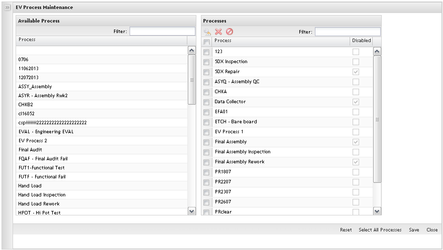
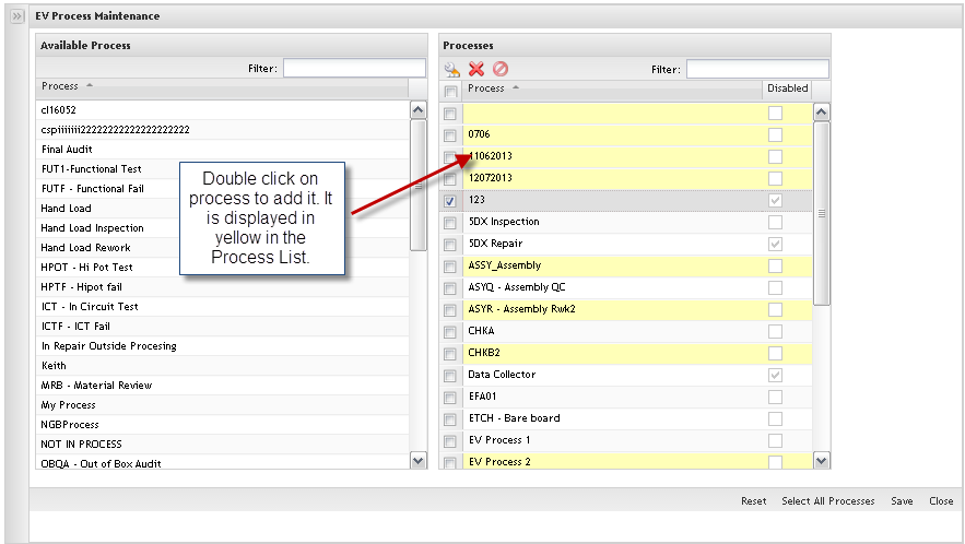
The processes are created in the SFDC Maintenance module. In EV, the user is able to '''Add Processes already created'''. The added Processes will be processes that EV will download to SFDC and check for Classes. In this step the user is able to add, edit, remove and re-add processes and process groups that will be managed inside the '''Employee Validation Module'''. | The processes are created in the SFDC Maintenance module. In EV, the user is able to '''Add Processes already created'''. The added Processes will be processes that EV will download to SFDC and check for Classes. In this step the user is able to add, edit, remove and re-add processes and process groups that will be managed inside the '''Employee Validation Module'''. | ||
| Line 1,146: | Line 1,149: | ||
The Process list main page is displayed. | The Process list main page is displayed. | ||
| − | ==== Listing Process ==== | + | ==== Listing Process ==== |
'''Figure 14: Processes List''' | '''Figure 14: Processes List''' | ||
| − | [[Image:SOP-5-I-MDS0023-C-MDS Employee Validation WIKI 14.png|frame|none | + | [[Image:SOP-5-I-MDS0023-C-MDS Employee Validation WIKI 14.png|frame|none]] |
In the Process List, the user can perform a filter by typing the process name in the Filter field. Click on '''Ok''' to confirm. | In the Process List, the user can perform a filter by typing the process name in the Filter field. Click on '''Ok''' to confirm. | ||
| − | ==== Adding Processes ==== | + | ==== Adding Processes ==== |
'''Figure 15: Add Process List''' | '''Figure 15: Add Process List''' | ||
| − | [[Image:SOP-5-I-MDS0023-C-MDS Employee Validation WIKI 15.png|frame|none | + | [[Image:SOP-5-I-MDS0023-C-MDS Employee Validation WIKI 15.png|frame|none]] |
The available processes are displayed to be added in EV. | The available processes are displayed to be added in EV. | ||
| Line 1,174: | Line 1,177: | ||
If there are multiple processes that are to be controlled by Employee Validation, yet fall into the same certification, these processes can be grouped together by defining a Process Group. Click on the '''Process Group Maintenance '''module. Follow the steps defined in the '''''Process Group Maintenance''''' topic for specific instructions on how to create Process Groups. | If there are multiple processes that are to be controlled by Employee Validation, yet fall into the same certification, these processes can be grouped together by defining a Process Group. Click on the '''Process Group Maintenance '''module. Follow the steps defined in the '''''Process Group Maintenance''''' topic for specific instructions on how to create Process Groups. | ||
| − | ==== Editing Processes ==== | + | ==== Editing Processes ==== |
To '''Edit (Enable and Disable) Processes''', follow the steps bellow: | To '''Edit (Enable and Disable) Processes''', follow the steps bellow: | ||
| Line 1,180: | Line 1,183: | ||
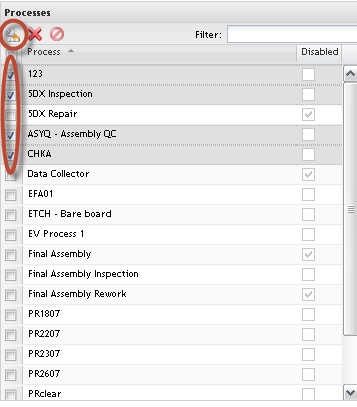
'''Figure 16: Edit Processes''' | '''Figure 16: Edit Processes''' | ||
| − | [[Image:SOP-5-I-MDS0023-C-MDS Employee Validation WIKI 16.png|frame|none | + | [[Image:SOP-5-I-MDS0023-C-MDS Employee Validation WIKI 16.png|frame|none]] |
1. Select the process (es) to be updated and click on '''Enable/Disable''' icon. | 1. Select the process (es) to be updated and click on '''Enable/Disable''' icon. | ||
| Line 1,190: | Line 1,193: | ||
After clicking on the edit icon, the process shows in dark gray. To commit this, click on '''Save'''. | After clicking on the edit icon, the process shows in dark gray. To commit this, click on '''Save'''. | ||
| − | ==== Removing Processes ==== | + | ==== Removing Processes ==== |
To '''Remove Processes''', follow the steps below: | To '''Remove Processes''', follow the steps below: | ||
| Line 1,196: | Line 1,199: | ||
'''Figure 17: Remove Processes''' | '''Figure 17: Remove Processes''' | ||
| − | [[Image:SOP-5-I-MDS0023-C-MDS Employee Validation WIKI 17.png|frame|none | + | [[Image:SOP-5-I-MDS0023-C-MDS Employee Validation WIKI 17.png|frame|none]] |
1. To '''Remove Processes''' from list, select the process and click on'''Remove''' button. | 1. To '''Remove Processes''' from list, select the process and click on'''Remove''' button. | ||
| Line 1,202: | Line 1,205: | ||
'''Note''': If the selected process has any associated certificate(s), the application will not allow the user to remove it, displaying an error message, otherwise, the process is displayed in gray. | '''Note''': If the selected process has any associated certificate(s), the application will not allow the user to remove it, displaying an error message, otherwise, the process is displayed in gray. | ||
| − | ==== Re-add Processes ==== | + | ==== Re-add Processes ==== |
1. To'''re-add''' processes, click on the '''Undo Delete''' button. | 1. To'''re-add''' processes, click on the '''Undo Delete''' button. | ||
| Line 1,208: | Line 1,211: | ||
'''Figure 18: Undo Delete Processes''' | '''Figure 18: Undo Delete Processes''' | ||
| − | [[Image:SOP-5-I-MDS0023-C-MDS Employee Validation WIKI 18.png|frame|none | + | [[Image:SOP-5-I-MDS0023-C-MDS Employee Validation WIKI 18.png|frame|none]] |
The selected process will change the color and continue displaying in the list. | The selected process will change the color and continue displaying in the list. | ||
| Line 1,216: | Line 1,219: | ||
---- | ---- | ||
| − | === Process Group Maintenance === | + | === Process Group Maintenance === |
Toaccess the'''Process Group Maintenance''', click on '''Process Group Maintenance '''option. | Toaccess the'''Process Group Maintenance''', click on '''Process Group Maintenance '''option. | ||
| − | ==== Adding Process Groups ==== | + | ==== Adding Process Groups ==== |
To add process groups, follow the steps below: | To add process groups, follow the steps below: | ||
| Line 1,226: | Line 1,229: | ||
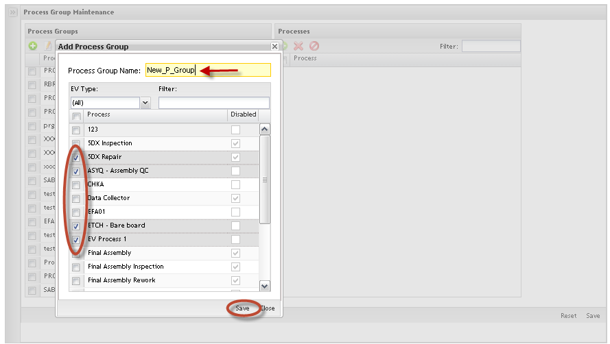
'''Figure 19: Add Process Groups''' | '''Figure 19: Add Process Groups''' | ||
| − | [[Image:SOP-5-I-MDS0023-C-MDS Employee Validation WIKI 19.png|frame|none | + | [[Image:SOP-5-I-MDS0023-C-MDS Employee Validation WIKI 19.png|frame|none]] |
1) To'''Add Process Groups''', click on '''Add '''icon, fill in the '''Process Group Name''' field and select the processes to be added into the process group. | 1) To'''Add Process Groups''', click on '''Add '''icon, fill in the '''Process Group Name''' field and select the processes to be added into the process group. | ||
| Line 1,238: | Line 1,241: | ||
Click on '''OK''' button to save the changes. | Click on '''OK''' button to save the changes. | ||
| − | ==== Editing Process Group Name ==== | + | ==== Editing Process Group Name ==== |
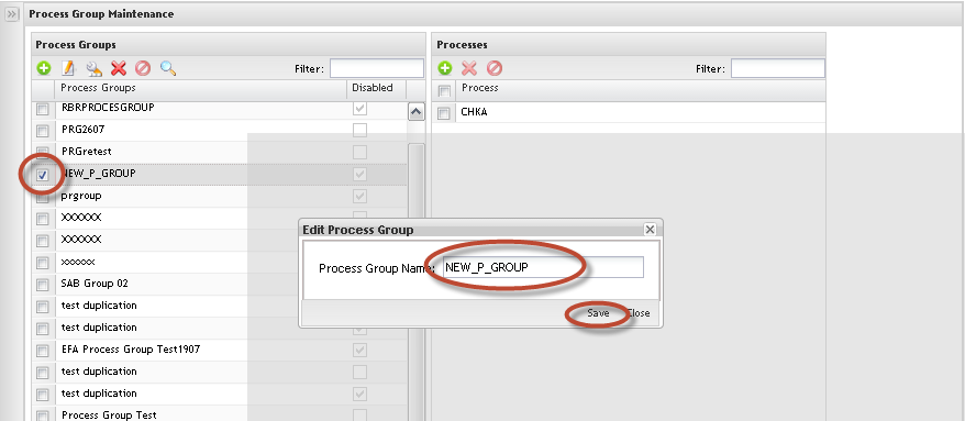
'''Figure 20: Edit Process Groups''' | '''Figure 20: Edit Process Groups''' | ||
| − | [[Image:SOP-5-I-MDS0023-C-MDS Employee Validation WIKI 20.png|frame|none | + | [[Image:SOP-5-I-MDS0023-C-MDS Employee Validation WIKI 20.png|frame|none]] |
1. To '''Edit Process Groups Name''', select the process group and click on '''Edit''' icon. | 1. To '''Edit Process Groups Name''', select the process group and click on '''Edit''' icon. | ||
| Line 1,248: | Line 1,251: | ||
Just the '''Process Group Name''' can be updated. Update the '''Process Group Name''' and click on '''OK''' to commit the change. To cancel, click on '''Cancel''' button. | Just the '''Process Group Name''' can be updated. Update the '''Process Group Name''' and click on '''OK''' to commit the change. To cancel, click on '''Cancel''' button. | ||
| − | ==== Editing Process Group Status ==== | + | ==== Editing Process Group Status ==== |
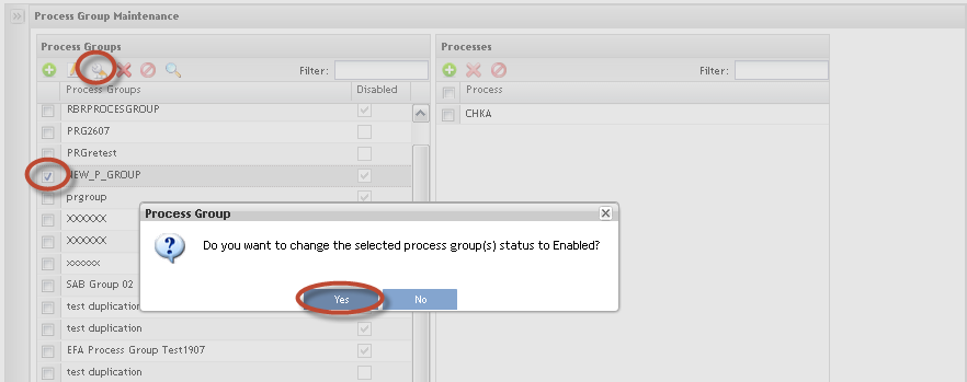
'''Figure 21: Change Process Group''' | '''Figure 21: Change Process Group''' | ||
| − | [[Image:SOP-5-I-MDS0023-C-MDS Employee Validation WIKI 21.png|frame|none | + | [[Image:SOP-5-I-MDS0023-C-MDS Employee Validation WIKI 21.png|frame|none]] |
1. To '''Change Process Group status,''' from list, select the item and click on '''Edit Status''' icon. | 1. To '''Change Process Group status,''' from list, select the item and click on '''Edit Status''' icon. | ||
| Line 1,260: | Line 1,263: | ||
2. Click on'''Yes '''button to commit the change. | 2. Click on'''Yes '''button to commit the change. | ||
| − | ==== Removing Process Group ==== | + | ==== Removing Process Group ==== |
'''Figure 22: Remove Process Group''' | '''Figure 22: Remove Process Group''' | ||
| − | [[Image:SOP-5-I-MDS0023-C-MDS Employee Validation WIKI 22.png|frame|none | + | [[Image:SOP-5-I-MDS0023-C-MDS Employee Validation WIKI 22.png|frame|none]] |
1. To '''Remove Process Group''' from list, select the process group and click on '''Remove''' icon. | 1. To '''Remove Process Group''' from list, select the process group and click on '''Remove''' icon. | ||
| Line 1,270: | Line 1,273: | ||
'''Note''': It is not possible to remove process groups if there are associated certificates. In this case, it is possible to only update the processes. | '''Note''': It is not possible to remove process groups if there are associated certificates. In this case, it is possible to only update the processes. | ||
| − | ==== Undo Delete Process Group ==== | + | ==== Undo Delete Process Group ==== |
'''Figure 23: Undo Delete Process''' | '''Figure 23: Undo Delete Process''' | ||
| − | [[Image:SOP-5-I-MDS0023-C-MDS Employee Validation WIKI 23.png|frame|none | + | [[Image:SOP-5-I-MDS0023-C-MDS Employee Validation WIKI 23.png|frame|none]] |
1. To undo delete a process group, click on'''Undo Delete''' icon. | 1. To undo delete a process group, click on'''Undo Delete''' icon. | ||
| Line 1,284: | Line 1,287: | ||
'''Process Maintenance:''' | '''Process Maintenance:''' | ||
| − | ==== Searching Process ==== | + | ==== Searching Process ==== |
'''Figure 24: Filter Processes''' | '''Figure 24: Filter Processes''' | ||
| − | [[Image:SOP-5-I-MDS0023-C-MDS Employee Validation WIKI 24.png|frame|none | + | [[Image:SOP-5-I-MDS0023-C-MDS Employee Validation WIKI 24.png|frame|none]] |
1. To '''Filter Processes''' already associated with a Process Group, enter the process name (at least 3 chars) in the '''Filter '''field. The process displays with the respective associated process group. | 1. To '''Filter Processes''' already associated with a Process Group, enter the process name (at least 3 chars) in the '''Filter '''field. The process displays with the respective associated process group. | ||
| − | ==== Adding Process ==== | + | ==== Adding Process ==== |
'''Figure 25: Add Process''' | '''Figure 25: Add Process''' | ||
| − | [[Image:SOP-5-I-MDS0023-C-MDS Employee Validation WIKI 25.png|frame|none | + | [[Image:SOP-5-I-MDS0023-C-MDS Employee Validation WIKI 25.png|frame|none]] |
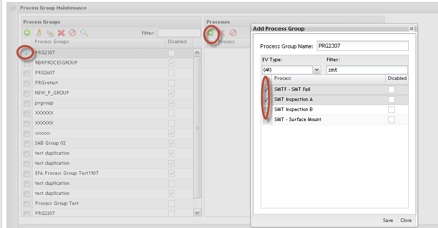
1. To '''Add Process''', select the Process Group and click on '''Add Process''' icon. | 1. To '''Add Process''', select the Process Group and click on '''Add Process''' icon. | ||
| Line 1,308: | Line 1,311: | ||
'''Note''': A Process can only belong to a single Process Group. | '''Note''': A Process can only belong to a single Process Group. | ||
| − | ==== Removing Process ==== | + | ==== Removing Process ==== |
'''Figure 26: Remove Process''' | '''Figure 26: Remove Process''' | ||
| − | [[Image:SOP-5-I-MDS0023-C-MDS Employee Validation WIKI 26.png|frame|none | + | [[Image:SOP-5-I-MDS0023-C-MDS Employee Validation WIKI 26.png|frame|none]] |
1. To '''Remove Process''', select the Process Group, select the process to be removed and click on '''Remove Process''' icon. | 1. To '''Remove Process''', select the Process Group, select the process to be removed and click on '''Remove Process''' icon. | ||
| Line 1,318: | Line 1,321: | ||
If the update on the process group affects existing certificates, the user is alerted and has the possibility to change the certificate before committing the change. | If the update on the process group affects existing certificates, the user is alerted and has the possibility to change the certificate before committing the change. | ||
| − | === Certificate Maintenance === | + | === Certificate Maintenance === |
The next step to configuring Employee Validation is to create the Certificates. Toaccess the'''Certificates''', click on '''Certificate Maintenance'''. | The next step to configuring Employee Validation is to create the Certificates. Toaccess the'''Certificates''', click on '''Certificate Maintenance'''. | ||
| Line 1,324: | Line 1,327: | ||
The main certificate maintenance page displays: | The main certificate maintenance page displays: | ||
| − | ==== Certificate List ==== | + | ==== Certificate List ==== |
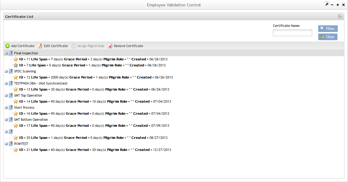
'''Figure 27: Certificate List''' | '''Figure 27: Certificate List''' | ||
| − | [[Image:SOP-5-I-MDS0023-C-MDS Employee Validation WIKI 27.png|frame|none | + | [[Image:SOP-5-I-MDS0023-C-MDS Employee Validation WIKI 27.png|frame|none]] |
Note that in the Certificate list, it is possible to see some unsynchronized certificates, which means that it has at least one process group that is out of date. In the next steps, the user will be able to turn non synchronized certificates into synchronized certificates. | Note that in the Certificate list, it is possible to see some unsynchronized certificates, which means that it has at least one process group that is out of date. In the next steps, the user will be able to turn non synchronized certificates into synchronized certificates. | ||
| − | ==== Adding Certificates ==== | + | ==== Adding Certificates ==== |
1. To'''Add Certificates and associate processes and process groups or Part/Family to Certificates''', click on '''Add Certificate''' in the Tasks area. | 1. To'''Add Certificates and associate processes and process groups or Part/Family to Certificates''', click on '''Add Certificate''' in the Tasks area. | ||
| Line 1,338: | Line 1,341: | ||
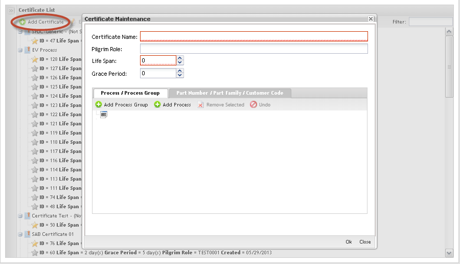
'''Figure 28: Add Certificate''' | '''Figure 28: Add Certificate''' | ||
| − | [[Image:SOP-5-I-MDS0023-C-MDS Employee Validation WIKI 28.png|frame|none | + | [[Image:SOP-5-I-MDS0023-C-MDS Employee Validation WIKI 28.png|frame|none]] |
The '''Certificate Maintenance''' screen displays: | The '''Certificate Maintenance''' screen displays: | ||
| Line 1,362: | Line 1,365: | ||
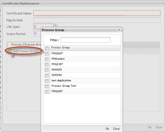
'''Figure 29: Certificate X Process/Process Group''' | '''Figure 29: Certificate X Process/Process Group''' | ||
| − | [[Image:SOP-5-I-MDS0023-C-MDS Employee Validation WIKI 29.png|frame|none | + | [[Image:SOP-5-I-MDS0023-C-MDS Employee Validation WIKI 29.png|frame|none]] |
The Certificate X Process / Process Group page displays: | The Certificate X Process / Process Group page displays: | ||
| Line 1,374: | Line 1,377: | ||
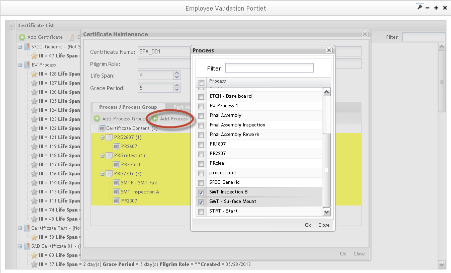
'''Figure 30: Certificate Maintenance Process/Process Group Tab''' | '''Figure 30: Certificate Maintenance Process/Process Group Tab''' | ||
| − | [[Image:SOP-5-I-MDS0023-C-MDS Employee Validation WIKI 30.png|frame|none | + | [[Image:SOP-5-I-MDS0023-C-MDS Employee Validation WIKI 30.png|frame|none]] |
To add Process to the process groups, click on Add Process. The added processes/process groups are displaying highlighted. | To add Process to the process groups, click on Add Process. The added processes/process groups are displaying highlighted. | ||
| Line 1,388: | Line 1,391: | ||
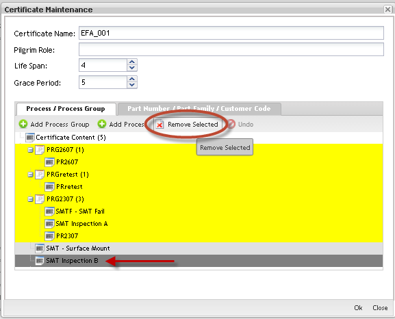
'''Figure 31: Remove Process Group''' | '''Figure 31: Remove Process Group''' | ||
| − | [[Image:SOP-5-I-MDS0023-C-MDS Employee Validation WIKI 31.png|frame|none | + | [[Image:SOP-5-I-MDS0023-C-MDS Employee Validation WIKI 31.png|frame|none]] |
Click the process/process group to select it and click on '''Remove Selected '''button. The removed process/process group displays in dark gray in the list. To '''Undo Delete ''''''CERTIFICATE ''''''Process/Process Group''', select it from list and click on '''Undo''' button. | Click the process/process group to select it and click on '''Remove Selected '''button. The removed process/process group displays in dark gray in the list. To '''Undo Delete ''''''CERTIFICATE ''''''Process/Process Group''', select it from list and click on '''Undo''' button. | ||
| Line 1,396: | Line 1,399: | ||
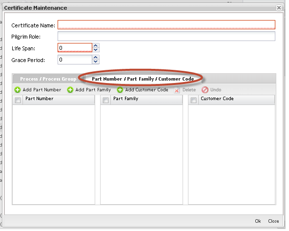
'''Figure 32: Part Number/Part Family/Customer Code Tab''' | '''Figure 32: Part Number/Part Family/Customer Code Tab''' | ||
| − | [[Image:SOP-5-I-MDS0023-C-MDS Employee Validation WIKI 32.png|frame|none | + | [[Image:SOP-5-I-MDS0023-C-MDS Employee Validation WIKI 32.png|frame|none]] <br> In addition, users can add Part Numbers/Family and Customer Codes to the Certificate. The rules to add, remove and undo remove are the same described for Process and Process Group. |
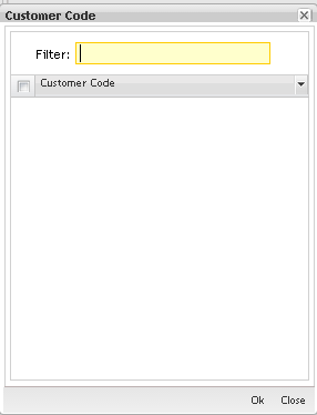
'''Figure 33: Customer Code''' | '''Figure 33: Customer Code''' | ||
| − | [[Image:SOP-5-I-MDS0023-C-MDS Employee Validation WIKI 33.png|frame|none | + | [[Image:SOP-5-I-MDS0023-C-MDS Employee Validation WIKI 33.png|frame|none]] |
To add customer code, select the item (s) in the list and click on '''OK'''. | To add customer code, select the item (s) in the list and click on '''OK'''. | ||
| Line 1,406: | Line 1,409: | ||
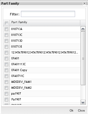
'''Figure 34: Part Family''' | '''Figure 34: Part Family''' | ||
| − | [[Image:SOP-5-I-MDS0023-C-MDS Employee Validation WIKI 34.png|frame|none | + | [[Image:SOP-5-I-MDS0023-C-MDS Employee Validation WIKI 34.png|frame|none]] |
To add part numbers/family, select the item (s) in the list and click on '''OK'''. | To add part numbers/family, select the item (s) in the list and click on '''OK'''. | ||
| − | ==== Editing Certificates ==== | + | ==== Editing Certificates ==== |
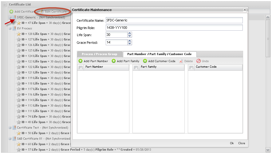
1. To '''Edit Certificates''', select the certificate in the Certificate List and follow the same instructions to Add Certificates: update the mandatory fields and click on '''OK''' to commit the change. | 1. To '''Edit Certificates''', select the certificate in the Certificate List and follow the same instructions to Add Certificates: update the mandatory fields and click on '''OK''' to commit the change. | ||
| Line 1,416: | Line 1,419: | ||
'''Figure 35: Certificate Maintenance''' | '''Figure 35: Certificate Maintenance''' | ||
| − | [[Image:SOP-5-I-MDS0023-C-MDS Employee Validation WIKI 35.png|frame|none | + | [[Image:SOP-5-I-MDS0023-C-MDS Employee Validation WIKI 35.png|frame|none]] |
<br>'''NOTE''': Every time the user adds a new Process on the Certificate, the application creates a new instance of that Certificate. All classes created before the Certificate changes will be linked to the old Certificate instance. | <br>'''NOTE''': Every time the user adds a new Process on the Certificate, the application creates a new instance of that Certificate. All classes created before the Certificate changes will be linked to the old Certificate instance. | ||
| Line 1,432: | Line 1,435: | ||
'''Figure 36: Certificate Instances''' | '''Figure 36: Certificate Instances''' | ||
| − | [[Image:SOP-5-I-MDS0023-C-MDS Employee Validation WIKI 36.png|frame|none | + | [[Image:SOP-5-I-MDS0023-C-MDS Employee Validation WIKI 36.png|frame|none]] |
'''GOLD STAR''' represents the last update; | '''GOLD STAR''' represents the last update; | ||
| Line 1,438: | Line 1,441: | ||
'''SILVER STARS '''are the old instances that are associated to the classes already created. | '''SILVER STARS '''are the old instances that are associated to the classes already created. | ||
| − | ==== Removing Certificates ==== | + | ==== Removing Certificates ==== |
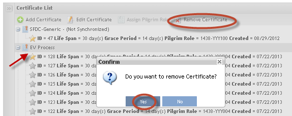
To '''Remove''' '''Certificates''' from the list, follow the steps below: | To '''Remove''' '''Certificates''' from the list, follow the steps below: | ||
| Line 1,450: | Line 1,453: | ||
'''Figure 37: Remove Certificate from List''' | '''Figure 37: Remove Certificate from List''' | ||
| − | [[Image:SOP-5-I-MDS0023-C-MDS Employee Validation WIKI 37.png|frame|none | + | [[Image:SOP-5-I-MDS0023-C-MDS Employee Validation WIKI 37.png|frame|none]] |
'''NOTE''': Certificates already associated with classes can not be removed. | '''NOTE''': Certificates already associated with classes can not be removed. | ||
| Line 1,456: | Line 1,459: | ||
---- | ---- | ||
| − | === Class Maintenance === | + | === Class Maintenance === |
Toaccess the'''Class Maintenance''', click on '''Class Maintenance''' option. The Class Maintenance main page is displayed: | Toaccess the'''Class Maintenance''', click on '''Class Maintenance''' option. The Class Maintenance main page is displayed: | ||
| Line 1,462: | Line 1,465: | ||
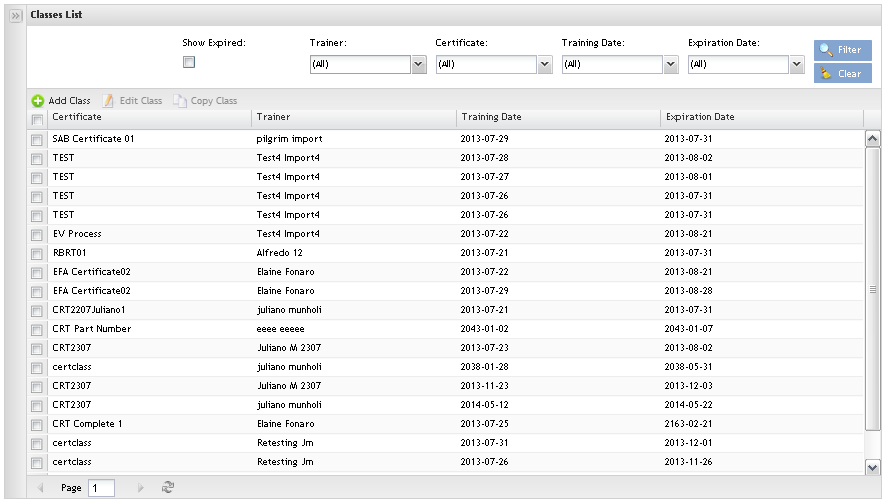
'''Figure 38: Class Maintenance''' | '''Figure 38: Class Maintenance''' | ||
| − | [[Image:SOP-5-I-MDS0023-C-MDS Employee Validation WIKI 38.png|frame|none | + | [[Image:SOP-5-I-MDS0023-C-MDS Employee Validation WIKI 38.png|frame|none]] |
The user is able to add, copy or edit classes and perform searches from the main class page. | The user is able to add, copy or edit classes and perform searches from the main class page. | ||
| − | ==== Adding Classes ==== | + | ==== Adding Classes ==== |
'''Figure 39: Add Class''' | '''Figure 39: Add Class''' | ||
| − | [[Image:SOP-5-I-MDS0023-C-MDS Employee Validation WIKI 39.png|frame|none | + | [[Image:SOP-5-I-MDS0023-C-MDS Employee Validation WIKI 39.png|frame|none]] |
1. Click on '''Add Class''' in the Menu bar. | 1. Click on '''Add Class''' in the Menu bar. | ||
| Line 1,478: | Line 1,481: | ||
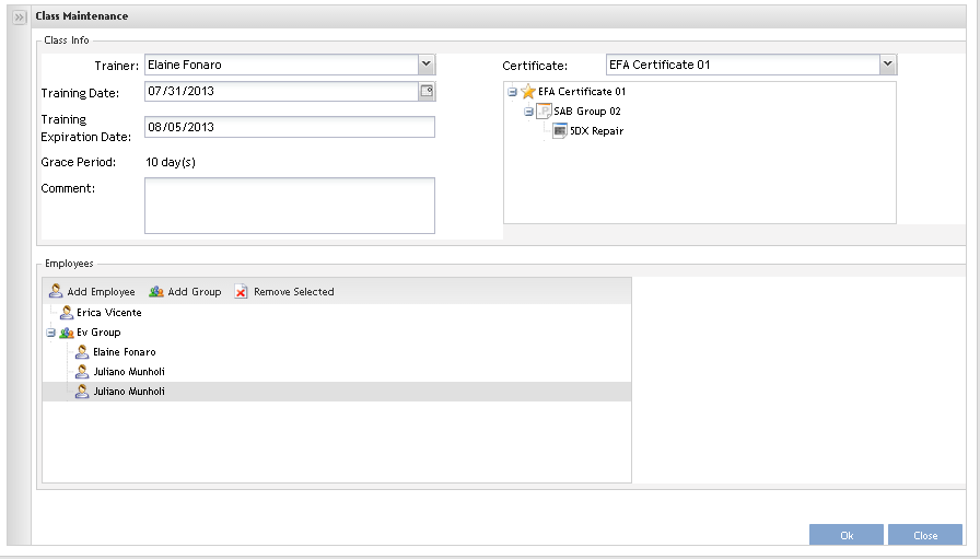
'''Figure 40: Class Maintenance''' | '''Figure 40: Class Maintenance''' | ||
| − | [[Image:SOP-5-I-MDS0023-C-MDS Employee Validation WIKI 40.png|frame|none | + | [[Image:SOP-5-I-MDS0023-C-MDS Employee Validation WIKI 40.png|frame|none]] |
1. Select the trainer, the certificate and the date for training from the drop down list. Selecting the certificate, the Grace Period and Training Expiration Date will be automatically filled. | 1. Select the trainer, the certificate and the date for training from the drop down list. Selecting the certificate, the Grace Period and Training Expiration Date will be automatically filled. | ||
| Line 1,488: | Line 1,491: | ||
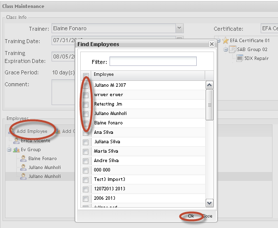
'''Figure 41: Add Employees''' | '''Figure 41: Add Employees''' | ||
| − | [[Image:SOP-5-I-MDS0023-C-MDS Employee Validation WIKI 41.png|frame|none | + | [[Image:SOP-5-I-MDS0023-C-MDS Employee Validation WIKI 41.png|frame|none]] <br> 1. Add the Employees clicking on '''Add Employee'''. |
The Find Employees popup displays to find Employees. | The Find Employees popup displays to find Employees. | ||
| Line 1,498: | Line 1,501: | ||
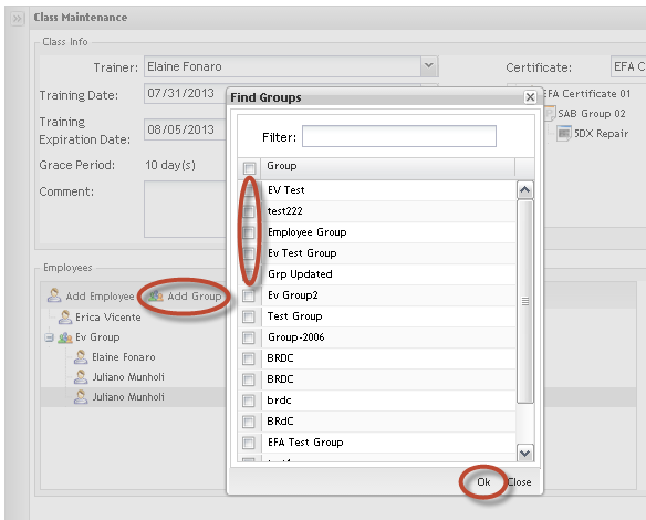
'''Figure 42: Add Employees Groups''' | '''Figure 42: Add Employees Groups''' | ||
| − | [[Image:SOP-5-I-MDS0023-C-MDS Employee Validation WIKI 42.png|frame|none | + | [[Image:SOP-5-I-MDS0023-C-MDS Employee Validation WIKI 42.png|frame|none]] |
1. Click on '''Add Group'''. | 1. Click on '''Add Group'''. | ||
| Line 1,510: | Line 1,513: | ||
'''NOTE''': The add Employees by group is a way to make adding employees fast and EV does not store group information, i.e. if the selected group has a new employee added in the future, he/she won<nowiki>’</nowiki>t be added to the class. | '''NOTE''': The add Employees by group is a way to make adding employees fast and EV does not store group information, i.e. if the selected group has a new employee added in the future, he/she won<nowiki>’</nowiki>t be added to the class. | ||
| − | ==== Editing Classes ==== | + | ==== Editing Classes ==== |
| − | To '''Edit Classes''', select the class to be edited and click on '''Edit''' icon. Follow the same steps performed to add classes. Click on '''Ok '''button to commit the changes. | + | To '''Edit Classes''', select the class to be edited and click on '''Edit''' icon. Follow the same steps performed to add classes. Click on '''Ok '''button to commit the changes. |
== SQC Configuration == | == SQC Configuration == | ||
| − | |||
| − | + | === Introduction === | |
| + | The SQC module was developed to '''store baseline and static data''' only. It is used for comparison against actual data collected by SFDC/MDS. The data can be imported from a spreadsheet, or data is manually entered. The data can be previously calculated cycle time data for processes and can also be the manufacturing time from Oracle for a particular part number. Regardless of how the data is entered into the module, it is simply reference data. The data is not automatically updated; therefore any changes must be done manually. | ||
| − | See below some important definitions for the user: | + | <br> See below some important definitions for the user: |
| − | # '''HPU''' (Hour Per Unit) - It measures how long time Operators take to produce a unit. | + | #'''HPU''' (Hour Per Unit) - It measures how long time Operators take to produce a unit. |
| − | # '''Cycle Time''' | + | #'''Cycle Time''' |
| − | '''Process cycle times:''' | + | '''Process cycle times:''' |
| + | <br> | ||
| − | # Short cycle times: the user logs in and “starts” a serial number, leaving the data collector location at the “Menu Selection” prompt while the process is being performed; | + | #Short cycle times: the user logs in and “starts” a serial number, leaving the data collector location at the “Menu Selection” prompt while the process is being performed; |
| − | # Medium to Long cycle times: the user starts a process and then the serial number will be released, or not remain at the Menu Selection prompt. This is also true of where a process consists of multiple test stations being run by a single operator, at a single data collector location. In this instance, units are started at different times, hence the need to “start” a unit, but free up the data collector location for the next unit starting on the next tester. As units complete the process, they are rescanned and passed or failed to the next location/process. | + | #Medium to Long cycle times: the user starts a process and then the serial number will be released, or not remain at the Menu Selection prompt. This is also true of where a process consists of multiple test stations being run by a single operator, at a single data collector location. In this instance, units are started at different times, hence the need to “start” a unit, but free up the data collector location for the next unit starting on the next tester. As units complete the process, they are rescanned and passed or failed to the next location/process. |
| − | '''NOTE''': Calculation of cycle time would be different between a short cycle time and medium to long cycle time processes. Medium to long cycle time processes would most likely include situations where shift changes, breaks, lunches, etc. are included. The cycle time calculations would need to take these times into account. | + | '''NOTE''': Calculation of cycle time would be different between a short cycle time and medium to long cycle time processes. Medium to long cycle time processes would most likely include situations where shift changes, breaks, lunches, etc. are included. The cycle time calculations would need to take these times into account. |
| − | ==='''Statistic Quality Control Setup'''=== | + | === '''Statistic Quality Control Setup''' === |
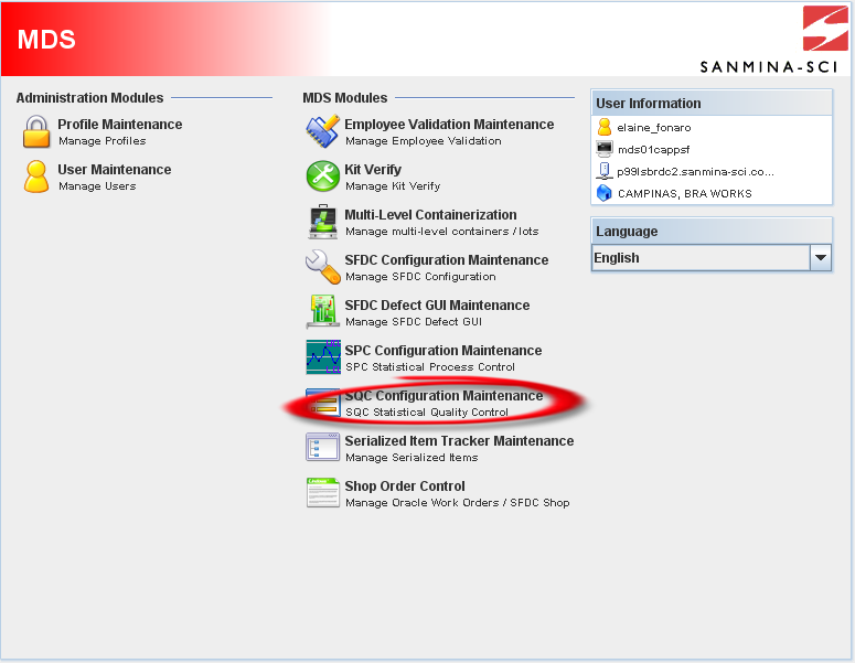
| + | To access SQC module, click on'''SQC Configuration Maintenance''' in the main MDS window. | ||
| − | + | <br> '''Figure 1: MDS Client Main Window – SQC ''' | |
| + | [[Image:Image01.png|800px|Image01.png]] | ||
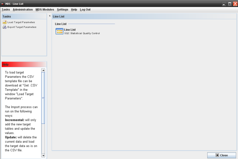
| − | + | <br> The SQC Maintenance window is displayed as follow: | |
| − | + | <br> '''Figure 2: SQC Main Page ''' | |
| + | [[Image:Image02.png|800px|Image02.png]] | ||
| − | The | + | <br> The'''MDS Line List '''screendisplays all available lines’ names and allows filtering data by entering data in the Line field. To clear the field content, click on '''Clear''' button and start a new filter. |
| + | <br> | ||
| − | + | === SQC – Line List Functionalities === | |
| − | + | There is just one available action to be executed from the Line List screen: Manage HPU Lines. See the next topics for further information. | |
| + | <br> | ||
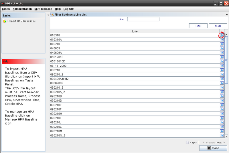
| − | + | === Managing HPU Lines === | |
| + | '''Figure 3: SQC Line List ''' | ||
| − | + | [[Image:Image03.png|800px|Image03.png]] | |
| − | |||
| + | <br> Click on '''Manage HPU Baselines''' icon in the list. The HPU manage screen is displayed. | ||
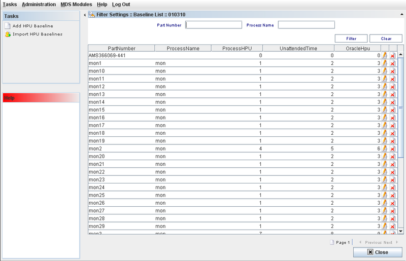
| − | + | <br> '''Figure 4: HPU Baselines Manage Screen''' | |
| − | '''Figure | ||
| − | [[ | + | [[Image:Image04.png|800px|Image04.png]] |
| + | <br> This screen allows the user to: | ||
| − | + | <br> | |
| + | #'''Add HPU Baselines;''' | ||
| + | #'''Import HPU Baselines;''' | ||
| + | #'''Edit HPU Baselines;''' | ||
| + | #'''Delete HPU Baselines;''' | ||
| − | ''' | + | There is a general filter by Part Number or Process Name. To execute the filter, enter the data and click on '''Filter'''. |
| − | + | <br> | |
| + | === Adding HPU Baselines === | ||
| − | + | To add an HPU Baseline, follow the steps below: | |
| + | <br> 1) Click on "'''Manage HPU Baselines'''" icon and click on "'''Add HPU Baseline'''" on the tasks panel. | ||
| − | + | <br> '''Figure 5: Add HPU - Task Panel''' | |
| − | |||
| − | |||
| − | |||
| − | + | [[Image:Image05.png|800px|Image05.png]] | |
| + | <br> A pop up to Add HPU Baselines is displayed: | ||
| − | + | <br> '''Figure 6: Add HPU Baseline''' | |
| − | |||
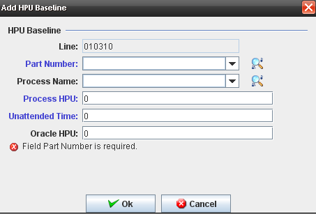
| + | [[Image:Image06.png]] | ||
| − | + | <br> The following fields are displayed and the user must enter data for the mandatory fields in blue: | |
| + | <br> <nowiki>* </nowiki>'''Line''' (Combo Box disabled) automatically selected, due to is the same line selected in the list. | ||
| − | ''' | + | <nowiki>* </nowiki>'''Part Number''' (Combo Box) |
| − | + | <nowiki>* </nowiki>'''Process Name''' (Combo Box) | |
| + | <nowiki>* </nowiki>'''Process HPU '''(Text Field) | ||
| − | + | <nowiki>* </nowiki>'''Unattended Time '''(Text Field) | |
| + | <nowiki>* </nowiki>'''Oracle HPU''' (Text Field) | ||
| − | ''' | + | <br> The'''Part Number''' and the '''Process Name''' are displayed in the drop down list from database. |
| − | + | Click on "'''OK'''" button after enter the mandatory fields to conclude. | |
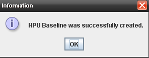
| + | <br> The application displays the following message: | ||
| − | + | <br> '''Figure 7: Successful Message''' | |
| + | [[Image:Image07.png]] | ||
| − | < | + | <br> The created HPU Baseline is displayed on the List screen. |
| − | + | === Editing HPU Baselines === | |
| − | + | To Edit an HPU baseline, the user must select an existing HPU line from the list and click on'''Edit '''icon. | |
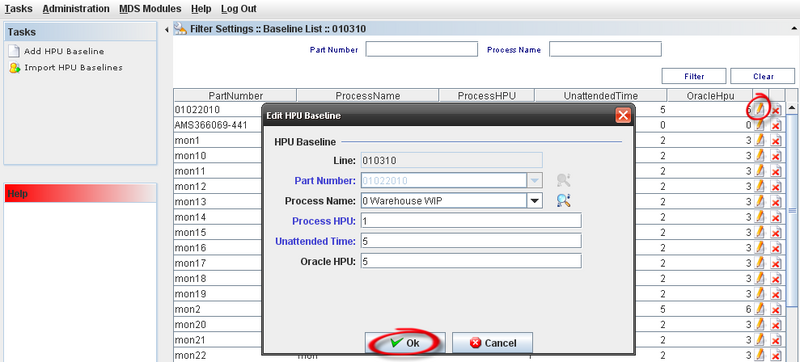
| − | < | + | <br> The HPU Baseline window displays with the Baseline information. The process to edit is the same as to add baselines. |
| − | < | + | <br> '''Figure 8: Edit HPU Baseline''' |
| − | + | [[Image:Image08.png|800px|Image08.png]] | |
| + | <br> Note: The'''Line''' and '''Part Number''' fields can not be updated: | ||
| − | + | <br> Click on "'''OK'''" button to conclude. | |
| − | + | <br> | |
| + | === Deleting HPU Baselines === | ||
| − | + | 1) On the Baseline List, select an existing HPU Baseline and click on '''Delete''' Icon | |
| + | <br> '''Figure 9: Deleting HPU''' | ||
| − | + | [[Image:Image09.png|800px|Image09.png]] | |
| − | + | <br> Click on "'''OK'''" button; | |
| + | A confirmation message displays. Click on '''Yes''' to conclude. | ||
| − | + | === Importing HPU Lines === | |
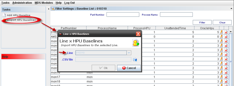
| − | + | Go to'''SQC Configuration Maintenance'''. The user can import HPU data directly form this screen by clicking on '''Import HPU Baselines '''in the Task Panel or click on '''"Manage HPU Baselines"''' icon. | |
| − | |||
| + | <br> '''Figure 10: Manage HPU Baseline''' | ||
| − | + | [[Image:Image010.png]] | |
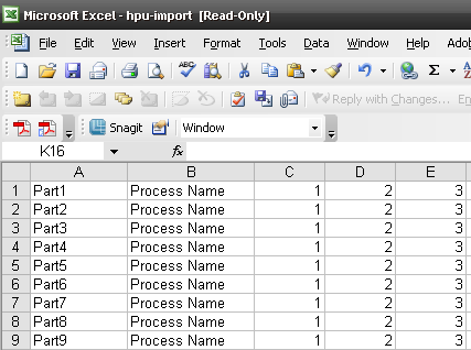
| + | <br> '''Figure 11: .CSV File Model''' | ||
| − | + | [[Image:Image011.png|800px|Image011.png]] | |
| − | + | <br> The .CSV file layout must be: Part Number, Process Name, Process HPU, Unattended Time and Oracle HPU. | |
| + | <br> '''Figure 12: Import HPU Baselines''' | ||
| − | + | [[Image:Image012.png|800px|Image012.png]] | |
| + | <br> 2) Click on "'''Import HPU Baselines'''" on the task on panel. The screen to import Baselines for Line is displayed with the following fields: | ||
| − | + | <br> <nowiki>* Line (Combo Box disabled)</nowiki> | |
| + | <nowiki>*.CSV File (Open Browser button displayed beside this field to select the path where the file is located in).</nowiki> | ||
| − | + | <br> 3) Click on "'''Open Browser'''" icon and select the .CSV file and click on "'''OK'''". | |
| − | |||
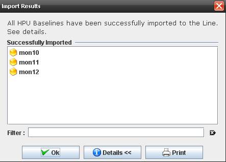
| + | <br> The "Report Results" screen is displayed with the following message: "All HPU Baselines have been imported to the line successfully. See Details" | ||
| − | '''Figure | + | <br> '''Figure 13: Report Result''' |
| − | [[ | + | [[Image:Image013.png]] |
| + | <br> To see the message details, click on "'''Details'''" button. | ||
| − | + | <br> '''Figure 14: Import Details''' | |
| − | + | [[Image:Image014.png]] | |
| − | + | <br> All part numbers are listed as "Successfully Imported" and all the HPU Baselines are displayed in the Baseline's list with exactly the same data from the .CSV file. | |
| − | |||
| + | <br> | ||
| − | + | === Printing HPU Lines === | |
| − | + | To print HPU Lines, go to MDS Client > SQC Configuration Maintenance and click on "'''Manage HPU Baselines'''" icon for the line. | |
| + | <br> 1) Click on "'''Import HPU Baselines'''" on the task panel and click on "'''Open Browser'''" icon and select the .CSV file. Click "'''OK'''". | ||
| − | ''' | + | <br> 2) Click on "'''Print'''" button. |
| − | + | <br> '''Figure 15: Print HPU Baselines''' | |
| + | [[Image:Image015.png]] | ||
| − | + | <br> A report is generated: | |
| + | <br> '''Figure 16: Generated Report''' | ||
| − | + | [[Image:Image016.png|800px|Image016.png]] | |
| − | + | === Load Target Parameters === | |
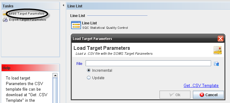
| + | To Load Target Parameters, go to MDS Client > SQC Configuration Maintenance and click on "'''Load Target Parameter'''" in the Tasks panel. | ||
| − | + | <br> '''Figure 17: Load Target Parameters''' | |
| + | [[Image:Image017.png]] | ||
| − | < | + | <br> To load target Parameters, the CSV template file can be download at '''"Get .CSV Template"''' in the "Load Target Parameters" pop up. |
| − | < | + | <br> The Import process can run on the following ways: |
| + | *Incremental: will only add the new target tables and update the values. | ||
| + | *Update: will delete the current data and load the target data as is on the CSV file. | ||
| − | + | Following the .CSV file template: | |
| + | <br> '''Part Number,Family,Process,Process ''' | ||
| − | + | '''Group,TargetYield,TargetTPhr,TargetDPMO,TargetCycleTime,TargetHPU,ResourceHr''' | |
| + | STRING(50)x,STRING(50)x,STRING(30)x,STRING(50)x,DECIMAL(999.99)+,INTEGER(2147483647)+,DECIMAL(99999.99)+, | ||
| − | + | DECIMAL(99999.99)+,DECIMAL(99999.99)+,DECIMALDECIMAL(99999.999999)+ | |
| − | + | <br> '''First line''': field name | |
| + | '''Second line''': field type ("x" means at least one must be filled out by line - the key, "+" means one or more fields must be filled out - the targets) | ||
| − | + | '''Third to last line''': target values - consumed from the higher level to deeper, ex: | |
| + | <br> 1) If a target is set only for a Mfg Line, only the "key" column Mfg Line must be filled out and the target values | ||
| − | + | <br> 2) If a targets is set for a Process on a specific Mfg Line only the "key" columns Mfg Line and Process must be filled out and the target values | |
| − | + | <br> If there are more than one target configuration for a specific "key" the data will be loaded but the reports can use both - please avoid that with a good organization on the CSV file. | |
| + | <br> The Import task does not validate if the data is correct on the CSV file, i.e. if the Part Numbers or Mfg Line exists on the MDS tables - please make sure all data set is already configured on MDS tables. | ||
| − | + | <br> | |
| + | === Export Target Parameters === | ||
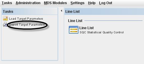
| − | + | The Export Target Parameters will export the previous loaded .CSV file tha contain the project parameters. This file is generated fro Nagios system. | |
| − | |||
| + | <br> '''Figure 18: Export Target Parameter''' | ||
| − | + | [[Image:Image018.png]] | |
| + | <br> These parameters are loaded to MDS Client and will be handled in the MESR. | ||
| − | + | <br> To export target parameters, click on '''Export Target Parameters''' in the Tasks panel, select the .CSV file and the path to save de file and click on '''Save'''. | |
| + | == Labor Tracking Maintenance == | ||
| − | + | === Labor Tracking Introduction === | |
| − | + | A new module was developed to allow users login labor and absence hours. It is used to control the employees work and when the employee is not working. A report can be generated with the result. | |
| + | *'''Labor Tracking''': allow users to Clock In and Clock Out labor or absence hours | ||
| + | *'''Labor Tracking Maintenance''': only Supervisors can access and change employee entries | ||
| + | *'''New commands to clock in and clock out labor''': “!!2clockin” and “!!2clockout” | ||
| − | + | === Labor Tracking Functionalities === | |
| + | This chapter teaches how the user manages the Labor Tracking module. It displays all functionalities and actions that can be performed by users and supervisors. | ||
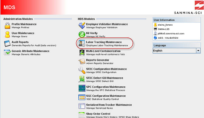
| − | + | <br> To access the Labor Tracking access the MDS Client and click on Labor Tracking Maintenance in the MDS Modules list. | |
| − | + | <br> '''Figure 1: MDS Client Modules''' | |
| − | + | [[Image:LT01.jpg|700px|LT01.jpg]] | |
| − | |||
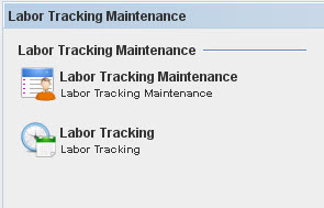
| + | <br> The Labor Tracking Maintenance main screen is displayed: | ||
| − | '''Figure | + | <br> '''Figure 2: Labor Tracking Sub-modules''' |
| − | [[ | + | [[Image:LT02.jpg]] |
| + | <br> Select a Labor Tracking sub-module to maintain.There is an integration with the SFDC system that allows users to use !! commands. | ||
| − | + | '''NOTE:''' Just '''Supervisor''' users have access to Labor Tracking Maintenance. | |
| + | <br> | ||
| − | + | === Labor Tracking === | |
| − | + | This screen allows the user to log the worked hours and absences. Follow the steps below to '''Clock In'''. | |
| − | |||
| − | + | <br> 1. Click on Labor Tracking Sub-module; | |
| + | 2. Select the '''Attendance Type''': | ||
| − | ''' | + | <br> '''Figure 3: Attendance Type''' |
| − | + | [[Image:LT03.jpg]] | |
| − | + | A) '''Absence''': to log the labor absence hours.B) '''Labor''': to log the employee worked hours. | |
| − | + | 3. Selecting Labor, select the '''Labor Type:''' | |
| + | <br> '''Figure 4: Labor Type''' | ||
| − | + | [[Image:LT04.jpg|700px|LT04.jpg]] | |
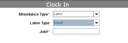
| − | ''' | + | #'''Direct Attendance''': for specific activity. For this labor type, enter the job# (work order for example); |
| − | ''' | + | '''Figure 5: Direct Labor Type''' |
| + | [[Image:LT05.jpg]] | ||
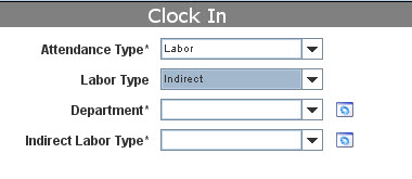
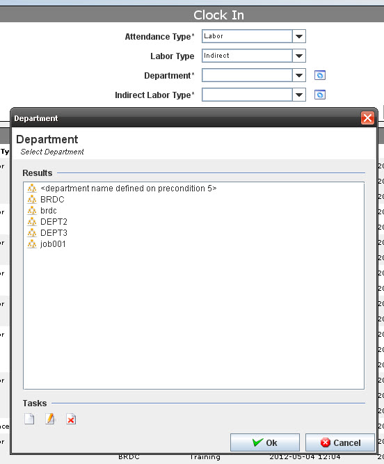
| − | + | B) '''Indirect Attendance''': for generic activity. For this labor type, select the Department and the Indirect Labor Type from the drop-down list; | |
| + | <br> '''Figure 6: Indirect Labor Type''' | ||
| − | + | [[Image:LT06.jpg]] | |
| + | Selecting '''Indirect Attendance''', select the '''Department''' and '''Indirect Labor Type''' from drop down list. It is possible to create, edit or delete Department and Indirect Labor Type clicking on '''Manage''' icon. | ||
| − | + | <br> '''Figure 7: Managing Department''' | |
| + | [[Image:LT07.jpg]] | ||
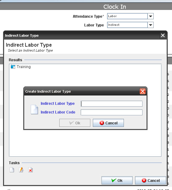
| − | + | <br> Managing Department and Indirect Labor Type: | |
| + | <br> '''Figure 8: Indirect Labor Type''' | ||
| − | + | [[Image:LT08.jpg]] | |
| − | |||
| + | <br> To manage the Indirect Labor Type (Add, Edit or Delete), click on the respective icons, fill the mandatory fields and click on '''OK'''. | ||
| − | ''' | + | 4- Click on '''Clock In''' button. The select data will be displayed in the Labor History. If you need to change any value, select the value and click on '''Change''' button. |
| − | + | 5- Click on '''Clock Out''' when you stop to work. | |
| + | <br> | ||
| − | + | === Labor Tracking Maintenance === | |
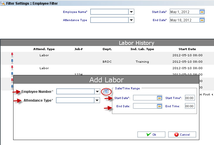
| + | This screen allows managing employee, adding labor and executing different filters in the Labor History. | ||
| − | + | === Filter === | |
| − | + | To filter, the user needs to fill the available mandatory fields and click on '''Filter'''. | |
| − | |||
| − | |||
| − | + | <br> '''Figure 9: Filter Settings''' | |
| − | |||
| − | |||
| − | + | [[Image:LT09.jpg|700px|LT09.jpg]] | |
| − | |||
| + | The results are displayed in the Labor History. | ||
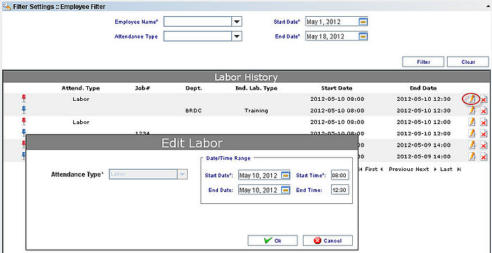
| − | + | It is possible to Edit or Delete the Labor Entered by clicking on the Delete/Edit icons: | |
| + | '''Figure 10: Edit Labor''' | ||
| − | + | [[Image:LT10.jpg|700px|LT10.jpg]] | |
| − | + | <br> The supervisor is able to update just the Data/Time range. It is not allowed to update the Attendance Type. | |
| + | <br> | ||
| − | + | === Add Labor === | |
| + | This screen allows the supervisor log the work hours to the employee. In addiction it is possible to maintain the Employee#, Department and Indirect Labor Type if Indirect Attendance were chosen. | ||
| − | ''' | + | Click on '''Cancel''' to cancel the action. |
| − | + | To Add Labor, click on '''Add Labor''' task in the Tasks panel. The screen to add Labor is displayed: | |
| + | <br> '''Figure 11: Add Labor''' | ||
| − | + | [[Image:LT11.jpg]] | |
| − | ''' | + | Update the necessary data and click on '''Ok''' button. |
| + | Click on the maintenance icon to manage employee numbers if necessary. | ||
| − | + | The difference between Add LDAP and Non LDAP user is that the LDAP user is fetching in the Sanmina database, so it is necessary to fill the '''HR Number'''. | |
| − | |||
| + | After enter the Data to add the labor, the result is displayed in the Labor History. | ||
| − | + | <br> | |
| − | + | === Manage Employee === | |
| + | '''Figure 12: Manage Employee''' | ||
| − | + | [[Image:LT12.jpg]] | |
| − | + | From this screen the supervisor is able to Add LDAP and non-LDAP users edit and delete users.1. To add an employee from web service, just select the user and click on '''Ok''' button.2. To add a non LDAP user, click on '''Add non LDAP User''' icon, enter the employee# and click on '''Ok''' button.3. To edit an user, select the user, click on '''Edit''' icon, update the employee# and click on '''Ok''' button;4. To delete a user, select the user and click on '''Delete''' icon. Click on '''Yes''' to complete the action. | |
| − | + | <br> | |
| − | + | === Labor Tracking – Using SFDC Commands === | |
| + | The clockin command is run at a data collector at any time after the operator logs in. | ||
| − | + | It is run as a !!2 command, which means that it is entered at the Serial Number prompt. | |
| − | + | If an operator is already clocked in, running the command again will automatically end the previous labor record, and begin a new record. | |
| − | + | <br> The format of the command is: | |
| − | ''' | + | '''!!2clockin.labor_type.labor_data''' |
| − | + | ''' labor_type labor_data''' | |
| − | + | 1 (direct labor) job_number (shop order) | |
| + | 2 (indirect labor) partment | ||
| − | + | <br> For example, to start a labor record for Shop Order 100501, scan: | |
| − | + | '''!!2clockin.1.100501''' | |
| − | + | <br> The clockout command is run at a data collector at any time after the operator logs in when there is an open labor record. | |
| + | <br> It is run as a !!2 command, which means that it is entered at the Serial Number prompt. | ||
| − | + | <br> The format of the command is: | |
| − | + | <br> ''' !!2clockout''' | |
| + | == Algorithm Tool == | ||
| − | + | === Introduction === | |
| + | The Shop Floor Data Collection System (SFDC) communicates interactively with the Customer Order Processing System (COPS), and Statistical Process Control/Statistical Quality Control (SPC/SQC). The Manufacturing Data System (MDS) makes the communication between these systems possible. | ||
| − | + | SFDC provides real-time information used by SPC/SQC and MESWeb to create quality control reports. The data configuration for SFDC PC is handled within the Manufacturing Data System (MDS), which is a complete factory automation system. The SFDC System uses barcode scanning, both manual and automated, to monitor and control a single product line or an entire plant. SFDC Configuration collects data, provides analysis, maintains unit histories, and controls product movement on the manufacturing floor. | |
| − | + | The system provides Access Control between the modules of the application, including the functionalities of each screen. The current version has an SFDC Configuration page which provides access to all sub modules pages and its functionalities (view, add, edit, delete, print and generate output file. | |
| + | '''Set up SFDC Configuration''' | ||
| − | To | + | 1. To access the SFDC Configuration, click on '''SFDC Configuration''' in the menu. The main SFDC Configuration and sub modules page is displayed: |
| − | + | <br> '''Figure 1: MDS Portal – SFDC Configuration Sub modules''' | |
| − | 5- | + | [[Image:SOP-5-I-MDS0028-C RA1 MDS Algorithm Tool 001.png|thumb|none|624px|SOP-5-I-MDS0028-C RA1 MDS Algorithm Tool 001.png]] |
| + | <br> NOTE: A user only has access to the modules assigned to his/her profile. | ||
| − | + | <br> | |
| − | |||
| − | === | + | === Algorithm Tool === |
| − | |||
| + | The Algorithm Tool provides the ability to create and modify serial number algorithms. The Algorithm Tool adheres to the format used by Sanmina customers and engineers when writing specifications for serial number algorithms. It is an integrated with the SFDC and generates serial numbers (Shop Order and Containerization modules) and MAC Addresses. | ||
| − | + | The main Algorithm Tool functionality is to trigger actions according to MDS parameters. | |
| − | + | ==== Algorithm Tool Main Page ==== | |
| − | + | To access the '''Algorithm Tool''', click on '''Algorithm Tool''' in the SFDC Configuration Maintenance menu. The Algorithm Browser displays: | |
| − | + | '''Figure 2: Algorithm Tool Browser''' | |
| − | + | [[Image:SOP-5-I-MDS0028-C RA1 MDS Algorithm Tool 01.png|thumb|none|624px|SOP-5-I-MDS0028-C RA1 MDS Algorithm Tool 01.png]] | |
| − | + | This Algorithm main page displays all defined algorithms. The user is able to'''Create Edit''', '''Copy''', '''Delete''', '''Import''' '''and Export '''and'''View''' the file or '''View Customcode record'''. See the next topics for further information. | |
| + | The '''filter feature''' allows filtering results by '''algorithm number range''', '''description''' and '''active status'''. When Type displays '''All '''it means that algorithms not created by the tool are displayed in the list. Enter the desired filter criteria and click on '''Filter'''. Click on '''Clear''' to clear the filter fields. | ||
| − | + | ==== Creating Algorithms ==== | |
| + | '''Note:''' As a '''general''' rule, when creating customer defined serial number algorithms, see customer serialization documentation to ensure correct algorithm format and functionality. This avoids the risk of generation and use of incorrect serialization formats. | ||
| − | + | 1- To create algorithms, click on '''Create Algorithm''' on main menu. | |
| − | |||
| − | + | '''Figure 3: Create Algorithm''' | |
| − | + | [[Image:SOP-5-I-MDS0028-C RA1 MDS Algorithm Tool 02.png|thumb|none|624px|SOP-5-I-MDS0028-C RA1 MDS Algorithm Tool 02.png]] | |
| + | The Algorithm maintenance window displays: | ||
| − | '''Figure | + | '''Figure 4: Algorithm Maintenance''' |
| − | [[ | + | [[Image:SOP-5-I-MDS0028-C RA1 MDS Algorithm Tool 03.png|thumb|none|624px|SOP-5-I-MDS0028-C RA1 MDS Algorithm Tool 03.png]] |
| − | + | 2- The '''Algorithm Number''' available at database is displayed. If necessary, it is possible to enter a special algorithm number. | |
| − | + | 3- Choose the '''algorithm type''' that determines how the algorithm will be used in production by selecting the algorithm type in the '''Type''' drop down list; | |
| − | + | '''Figure 5: Algorithm Types''' | |
| − | + | [[Image:SOP-5-I-MDS0028-C RA1 MDS Algorithm Tool 04.png|frame|none|SOP-5-I-MDS0028-C RA1 MDS Algorithm Tool 04.png]] | |
| + | The Algorithm Tool currently supports the following algorithm types: | ||
| − | + | *'''Shop Order Algorithm''' - This algorithm type is used to generate serial numbers from the SFDC Shop Order Release screen in MDS. | |
| − | ''' | + | *'''SFDC Container Algorithm''' - This algorithm type is used to generate serial numbers from the SFDC Container menus in MDS. |
| + | *'''COPS Algorithm''' - This algorithm type is used to generate serial numbers from the COPS menus in MDS. | ||
| + | *'''GENCOMP2 Algorithm''' - This algorithm type is used to generate serial numbers using the GENCOMP2 command from SFDC. | ||
| + | *'''CRE8MAC (MAC ID)''' Algorithm - This algorithm type is used to generate serial numbers using the CRE8MAC command from SFDC. | ||
| + | *'''Label Algorithm''' - This algorithm type is used to generate serial numbers for labels. The Label algorithm type requires that a particular label be programmed by IT to call the specific serial number algorithm using this algorithm type. | ||
| + | *'''Non Serial Nbr Algorithm - '''This algorithm type is used when no serial is generated. | ||
| + | *'''CRE8MAC2 '''- sends e-mails alerting the user when the MAC ADDRESS quantity is low. | ||
| + | *'''General '''- created for general purposes. | ||
| + | *'''Skeleton Algorithm''' - to be used in the release process in the Shop Order Module. | ||
| + | *'''CHGIDALG Algorithm''' - This algorithm type is used to generate serial numbers using the CHGIDALG command from SFDC. | ||
| − | + | *'''CHGIDALG2 (Ref Des)''' - This algorithm type is used to generate serial numbers using the CHGIDALG2 command from SFDC. The reference designator parameter is passed to the CHGIDALG2 command from the MDS Parameters in the Algorithm Tool. | |
| + | *'''COPS Container Algorithm''' - This algorithm type is used to generate serial numbers from the COPS Container menus in MDS. | ||
| + | *'''CRE8MAC3 (Reuse Mac IDs)''' - This algorithm type is used to generate serial numbers using the CRE8MAC3 command from SFDC. The CRE8MAC3 command sends e-mails alerting the user when the MAC ADDRESS quantity is low. The CRE8MAC3 command also seeks out ranges of serial numbers that have not yet been generated and assigned. | ||
| + | *'''MACCOMP2 (Email)''' - This algorithm type is used to generate serial numbers using the MACCOMP2 command from SFDC. The MACCOMP2 command sends e-mails alerting the user when the MAC ADDRESS quantity is low. | ||
| + | *'''Send Serial File Algorithm''' - This algorithm type is used to generate serial numbers using the SENDSERIALFILE command from SFDC. The SENDSERIALFILE command sends a file that lists the generated serial numbers to users. The SENDSERIALFILE command also sends e-mails alerting the user when the serial number quantity is low. | ||
| − | + | '''An existing algorithm may not be changed to a different algorithm type under the following conditions:''' | |
| + | *If the algorithm has already been used in production. This condition can be overridden by setting the latest serial number to blank in the Latest SN Menu of the Testing Facility. | ||
| + | *If the latest serial number has already been set to a non-blank value in the Latest SN Menu of the Testing Facility. This condition can be overridden by setting the latest serial number to blank in the Latest SN Menu of the Testing Facility. | ||
| − | + | '''A Shop Order algorithm '''type may not be changed to a different algorithm type under the following conditions:<br> | |
| − | |||
| − | + | *If the algorithm definition contains an element where the '''Variable Length''' attribute is set to "'''yes'''". | |
| + | *If the algorithm definition contains an element where the Previous Must Match Current attribute is set to "yes". | ||
| + | *If the algorithm definition contains an element where the Return Previous Value attribute is set to "'''yes'''". | ||
| + | *If the algorithm definition contains a "sequence" element where the Suppress Zeros attribute is set to "'''yes'''". | ||
| + | *If the algorithm definition contains an "order nbr" element. | ||
| − | + | 4- Enter a description to <nowiki>’</nowiki>'''Description Note'''<nowiki>’</nowiki> field. | |
| + | {| width="100%" cellspacing="2" border="0" | ||
| + | |- | ||
| + | | '''Description Note''': This field allows the user to specify a note that is appended to the algorithm description | ||
| + | | in algorithm lists. The Algorithm Description Note can not be greater than 30 characters. | ||
| + | |} | ||
| − | + | '''Description Note Policy''': When this attribute is set to "'''Append'''", and Description Note is not blank, the Description Note is appended to the algorithm description. This is the default for this attribute. However, sometimes it may be desirable to exclude the algorithm sequence information from the algorithm description. To exclude the sequence information from the algorithm description, set the "'''Description Note Policy'''" to "'''Replace'''". | |
| − | + | '''Note''': As a general rule, set the "Description Note Policy" to Replace when utilizing customer serialization documentation, and enter customer name, and document number as the Description Note (as space permits). This aids in Algorithm selection as well as easy reference to customer documentation if/when the need arises. | |
| − | ''' | + | '''Verify the algorithm description displays before deploying algorithm.''' |
| − | + | 5- Select the bypass "'''yes'''" or "'''no'''" option to "'''Bypass Duplicate'''". | |
| − | + | '''Bypass Duplicate''': When Bypass Duplicate is set to "Yes", generated serial numbers that match existing serial numbers will be bypassed and the next unique serial number will be returned instead. When Bypass Duplicate is set to "No", a generated serial number that matches an existing serial number will cause an error to be returned and halts the release process. | |
| + | '''Note''': As a general rule, it is preferred to set Bypass Duplicate to "No". ONLY set Bypass Duplicate to "Yes" when using the exported serial file to import and/or print serial numbers, or if there is alternative means of identifying the bypassed serial number(s). This avoids the risk of printing bypassed (duplicate) serial number(s) during label print process when utilizing an external application or software. | ||
| − | + | 6- Enter a value greater than 1 on'''Bypass Duplicate MAX''' field and click on '''Ok''' button. | |
| − | ''' | + | '''Bypass Duplicate MAX''': When Bypass Duplicate is set to "Yes", then Bypass Duplicate Max must be set to a non-zero value, indicating the maximum number of existing serial numbers that may be bypassed. The maximum value is 9999 to avoid a "runaway transaction". When Bypass Duplicate is set to "No", Bypass Duplicate Max must be set to zero. |
| + | ==== Create Element ==== | ||
| − | + | There are 21 element types available, as displayed in the "'''Element Type'''" list: | |
| + | '''Figure 5: Element Type''' | ||
| − | + | [[Image:SOP-5-I-MDS0028-C RA1 MDS Algorithm Tool 05.png|frame|none|SOP-5-I-MDS0028-C RA1 MDS Algorithm Tool 05.png]] | |
| + | Note that "'''date-type'''" elements include the specific element type "'''date'''", as well as the other date-oriented elements, such as "'''custom period'''" and "'''year code'''" (all element types--except constant, variable, part, order number, and sequence--are date oriented). Note the distinction between the "'''date element'''" and "'''date-oriented elements'''" (which includes the "date" element). These two terms will be used as appropriate, and are not interchangeable. | ||
| − | + | In general, any combination of these element types may appear in a single serial number algorithm definition in any order. A single element type may appear more than once. However, there are a few restrictions: | |
| + | *The "'''order nbr'''" element type will not be available in the list of available element types if the algorithm type is not "Shop Order". | ||
| − | ''' | + | *There may be only one "'''month 24'''" element type in a serial number algorithm definition. The "month 24" element will not be available in the list of available element types if there is already a "month 24" element in the algorithm definition. |
| − | + | *Standard calendar element types will not be available in the list of available element types if there is already a fiscal-calendar element in the algorithm definition. | |
| − | |||
| − | + | *Fiscal calendar element types will not be available in the list of available element types if there is already a standard calendar element in the algorithm definition. | |
| − | + | *A variable-length or zero-suppressed "sequence" element must be the last element in a serial number algorithm definition (see the "sequence" element for more details). | |
| − | + | '''Common Element Attributes:''' | |
| − | + | Many element attributes are shared by the various element types: | |
| − | + | *'''Element Name''': Every element (except the Constant element) has an Element Name (the Constant element has a Constant Value instead). The name of an element is made up of one or more instances of a single letter; this letter may not be used in the element name for any other element. All values entered in upper case in the element name field will be converted to lower case. The length of an element in the serial number definition is determined by the length of the value entered in the element name field. | |
| + | *'''Element Type''': Every element has an Element Type, as selected from the "Element Types" list. | ||
| − | ''' | + | *'''Element Description:''' Every element has an Element Description. This is an optional, 20-character text field where information may be recorded about a given algorithm element. This value does not affect the function of the serial number algorithm. |
| − | + | *'''Element Format''': Most element types require an Element Format, with the exception of the "date" elements. Valid element formats are "Numeric", "Alphabetic", "Alpha-Numeric", "Numeric-Alpha", "Hexadecimal", and "Character". The "Character" format allows all printable characters (except the space) to be included in the element. Valid formats for the "Date" element are "Year", "Day of Year", "Month", "Day of Month", "Week", "Day of Week". | |
| − | |||
| − | + | *'''Format Exclude''': Element types that have the Format attribute (except for "Date" element) also provide for the exclusion of characters from the element format. Letters, numbers, and other characters entered into the format exclude field, for a given element, will not be permitted to appear in serial numbers. For example, a Sanmina-SCI customer may specify that the sequence number of the serial number may not contain the letters "I" or "O". Enter excluded characters one after the other, as it is not required to separate them with commas or spaces. If characters are separated with spaces, the spaces will be removed automatically. If characters are separated with commas, the commas will also be removed unless the Element Format is "Character". In this case the comma character will be retained as it may be desired to exclude the comma character from the element format. | |
| + | *'''Format Pattern''': This field is present on many detail screens. It is a read-only field that shows the Element Format, including the Format Exclude characters, in a concise pattern display. | ||
| + | *'''Reset Sequence Using This Element''': Setting this attribute to "Yes", a "part", or any of the date-type, elements may be used to reset the value of the algorithm sequence to its minimum value. The algorithm sequence value will reset to its minimum value if the new value of the "reset" element is different from the value used in the latest serial number. | ||
| + | *'''For date-type element''', the date value in the latest serial number, for that element, is compared to the current date. If the current date is different the algorithm sequence will be reset to the minimum value. This is the default for date-type elements. | ||
| − | + | *'''For "part" element''', the value in the latest serial number, for that element, is compared to the current value in the part maintenance field selected for this element. If the current value is different the algorithm sequence will be reset to the minimum value. By default, the Reset Sequence using this Element attribute is set to "No" for "part" elements. | |
| − | |||
| − | + | *'''Previous Must Match Current''': Set this attribute to "Yes" when the value in the starting serial number of a "part", or a date-type, element is required to match the current value. In the case of a date-type element, the value of the element in a serial number must match the current date, else an error is returned upon release. For a "part" element, the value of the element in a serial number must match the current value in the part maintenance field selected for this element, else an error es returned upon release. This option is available for type "Shop Order Algorithm" only. It may not be used if either the Reset Sequence using this Element or the Return Previous Value attribute is set to "Yes". The default for this attribute is "No". | |
| − | + | *'''Return Previous Value''': Set this attribute to "Yes" if it is required to return the same date-type element value as the previous serial number. The value in the date element in the new serial number will be the same as the previous serial number regardless of the current date. This option is available for type "Shop Order Algorithm" only. It may not be used if either the Reset Sequence using this Element, or the Previous Must Match Current, attribute is also set to "Yes". The default for this attribute is "No". | |
| − | + | *Note that '''The Reset Sequence Using This Element''', the '''Previous Must Match Current''', and the '''Return Previous Value''' attributes are mutually exclusive. These attributes appear together on a detail screen, yet only one of may be set to "Yes" at a time. | |
| − | ''' | + | *'''Minimum Value''': The value of an element in a serial number must be greater than or equal to the value in the minimum value field. |
| − | + | *'''Maximum Value''': The value of an element in a serial number must be less than or equal to the value in the maximum value field. | |
| − | + | *Note: '''Minimum Value''' and the '''Maximum Value''' fields are optional, except for Sequence Elements, where they are mandatory. In cases where minimum and/or the maximum value fields are left blank, the respective default values will be the smallest and the largest values possible with the format specified for that element. | |
| − | + | '''Date-Type Element Attributes:''' | |
| − | + | Date-type elements include the element specifically called "date" as well as the other date-oriented elements; such as "custom period", "year code", etc. | |
| − | ''' | + | *'''Calendar Type''': The calendar type is either "'''Standard'''" or "'''Fiscal'''". |
| − | + | *The '''Standard calendar''' is the most commonly used; it '''begins on January 1 and ends on December 31'''. | |
| − | ''' | + | *The '''Fiscal calendar''' is used where the year is made up of 52 or 53 weeks and '''generally begins on or around January 1'''. The '''ISO-8601 calendar''' is a fiscal calendar defined such that '''the first week of the year is the week containing the first Thursday of the standard calendar year'''. |
| − | + | *'''First Day of Week''': The '''first day of the Fiscal week may be either Sunday''' (as in the Sanmina-SCI calendar) '''or Monday'''. The first day of the week applies only to fiscal calendars and has no significance inr the standard calendar. | |
| − | The | + | *'''Eaton Calendar''': If the calendar type is "Fiscal", then the Eaton Calendar may be used (otherwise, the fiscal calendar will be one defined by ISO-8601). '''The Eaton Calendar''' is defined such that '''the first week of the fiscal year is the week containing January 1'''. '''The First Day of the Week in the Eaton calendar is always Sunday'''. However, in an apparent anomaly, the days of the week are numbered beginning with Monday, such that Monday = 1, Tuesday = 2, and Sunday = 7. The name "Eaton Calendar" refers to the name of the company that uses this fiscal calendar. This calendar is available for use in any algorithm. |
| − | ''' | + | '''Note''': Certain element types, such as the month-type element, for instance, require a standard calendar. Other element types, such as a week-type element, require a fiscal calendar. A few element types, such as year-type elements, allow for either a standard or fiscal calendar. The type of calendar required for an element is displayed in the Element Types list. |
| − | + | If the algorithm definition already contains an element that requires a standard calendar, then those element types requiring a fiscal calendar will not be available for selection in the Element Types list; likewise, if the algorithm definition already contains an element that requires a fiscal calendar, then those element types requiring a standard calendar will not be available for selection in the Element Types list. To view all available element types, observe the Element Types list when adding an element to an algorithm that currently had no elements. | |
| − | + | A "date" element may be defined with an Element Format which requires a standard calendar ("day of year", "month", or "day of month"), with one that requires a fiscal calendar ("week" or "day of week"), or with one that can be either ("year"). If the algorithm definition already contains a "date" element with an element format of "week" or "day of week", then the element formats "month", "day of year", and "day of month" will not be available for other "date" elements and Calendar Type will be set to "Fiscal". If the algorithm definition already contains a "date" element with a element format of "month", "day of year", or "day of month", then the element formats "week" and "day of week" will not be available for other "date" elements and Calendar Type will be set to "Standard". | |
| − | + | '''Constant Element:''' | |
| − | '''Figure | + | '''Figure 6: Element Maintenance: Constant Element''' |
| − | [[Image:SOP-5-I-MDS0028- | + | [[Image:SOP-5-I-MDS0028-C RA1 MDS Algorithm Tool 06.png|frame|none|SOP-5-I-MDS0028-C RA1 MDS Algorithm Tool 06.png]] |
| − | The | + | The Constant Value of a "constant" element may contain any characters found on the keyboard. When serial numbers are generated, the constant value will appear exactly as it is entered (except that lower-case letters will be converted to upper case). The value of a constant element will always be the same, as defined in the Element Name field on the constant detail screen. |
| − | + | If a "constant" element is to have one or more trailing blanks, then the number of blank characters following the element name must be entered into the Trailing Blanks field; otherwise, trailing blanks typed into the Constant Value field will be discarded. Leading blanks may simply be entered in the element name and will be retained automatically. | |
| − | |||
| − | |||
| − | |||
| − | |||
| − | |||
| − | |||
| − | |||
| − | |||
| − | |||
| − | |||
| − | + | The length of a constant element in the serial number definition is equal to the length of the value entered in the Element Name field (including any leading blanks) plus the number of Trailing Blanks. | |
| − | |||
| − | |||
| − | |||
| − | |||
| − | + | Validation messages are displayed when element data has exceeded the maximum character limit, as follows: | |
| − | * | + | *Lower case is converted to upper case |
| − | * | + | *Element Name can not be <nowiki>></nowiki> 20 characters |
| + | *Element Description <nowiki>></nowiki> 20 characters | ||
| + | *Trailing Blanks <nowiki>></nowiki> 99. | ||
| − | ''' | + | '''Variable Element:''' |
| − | |||
| − | |||
| − | |||
| − | |||
| − | |||
| − | + | '''Figure 7: Element Maintenance: Variable''' | |
| − | + | [[Image:SOP-5-I-MDS0028-C RA1 MDS Algorithm Tool 07.png|frame|none|SOP-5-I-MDS0028-C RA1 MDS Algorithm Tool 07.png]] | |
| − | | | ||
| − | | | ||
| − | + | The value of a variable element may be different, from one serial number release to another, as long as the value meets the specification on the variable detail screen. | |
| − | ''' | + | '''Part Element:''' |
| − | ''' | + | '''Figure 8: Element Maintenance: Part''' |
| − | + | [[Image:SOP-5-I-MDS0028-C RA1 MDS Algorithm Tool 08.png|frame|none|SOP-5-I-MDS0028-C RA1 MDS Algorithm Tool 08.png]] | |
| − | + | The value of a part element is taken from a field in the part maintenance record at the time the serial number is generated. | |
| − | + | The following rules apply to "Part" elements: | |
| − | ''' | + | *'''Part Field''': Select one of the fields available in the Part Field list. This indicates where the serial number data for the part element will come from. |
| − | + | *'''Part Field Start Position''': This indicates the starting position, in the part field, for the selection of data for the part element. | |
| − | ''' | + | *'''Length''': This indicates how many characters will be selected from the part field. The selection of data, from the starting position, can be made in either of two ways: (1) to the end of the part field. (2) For a number of characters equal to the length of the part element. |
| − | + | *'''Direction''': This will determine from which end of the "part" or "shop order" Value the sub-string will be selected. The options will be "From beginning" and "From end". The "Direction" field will affect how "Field start position" and "Length" are applied to the "Value" field. It a text field, with values of "begin" or "end". | |
| − | + | *'''Test Part Value''': This is the data that will be used to test the part element in the Test Algorithm step. | |
| − | ''' | + | *'''Variable Length''': Set the Variable Length attribute to "'''Yes'''" to allow a part element to be of variable length. The length must not be less than that specified in the '''Minimum Length''' attribute, nor greater than the length of '''Element Name'''. Also, the length of the part element in the starting serial number must be the same as the length of the selected value in the part maintenance field. For a variable-length part element, the Length field must be set to "End of Part Field", since those characters selected determine the length of the part element for a given serial number. |
| − | + | *A "Part" element may be set to variable-length only for a "Shop Order" algorithm. There may be only one variable-length "Part" element in a serial number algorithm definition. A variable-length "Part" element may not be in the same algorithm definition as a variable-length or zero-suppressed "Sequence" element. | |
| − | + | *'''Minimum Length''': For a variable-length element, the Minimum Length '''must be less than the length of the Element Name but not less than 1'''. For a non-variable-length element, the minimum length will automatically be set to equal the length of the Element Name. | |
| − | + | *'''Minimum Value''': if this attribute is not blank, the value of the part element in the latest serial number and the value of the part maintenance field must be greater than, or equal to, the Minimum Value. | |
| − | * | + | *'''Maximum Value''': If this attribute is not blank, the value of the part element in the latest serial number and the value of the part maintenance field must be less than, or equal to, the Maximum Value. |
| − | + | <br> '''Shop Order Element''': This element will function like the "part" element. The only differences will be in the name of the element type, "shop order 2", and the list of "Fields" in the drop-down list. Otherwise, the "part" and "shop order 2" element types will function identically. | |
| − | + | <br> '''Figure 09A: Shop Order 2 Element''' | |
| − | + | [[Image:SOP-5-I-MDS0028-C RA1 MDS Algorithm Tool 08A.png|frame|none|SOP-5-I-MDS0028-C RA1 MDS Algorithm Tool 08A.png]] | |
| − | + | The "Fields" in the drop-down list for "shop order 2" will be "shop_order_number", "revision", & "user_defined" and "date"; | |
| − | + | Was requested to add also, a new setting for the "part" and "shop order 2" element types: "Direction". This will determine from which end of the "part" or "shop order" Value the substring will be selected. The options will be "From beginning" and "From end". The "Direction" field will affect how "Field start position" and "Length" are applied to the "Value" field. We can call the new element field "db-fld-direction" and make it a text field, with values of "begin" or "end". | |
| − | + | <br> | |
| − | + | '''Order Number Element''': | |
| − | + | The Order Number element may be used with the "Shop Order Algorithm" type only. | |
| − | + | '''Date Element''': | |
| − | + | '''Figure 10: Element Maintenance: Date''' | |
| − | + | [[Image:SOP-5-I-MDS0028-C RA1 MDS Algorithm Tool 09.png|frame|none|SOP-5-I-MDS0028-C RA1 MDS Algorithm Tool 09.png]] | |
| − | |||
| − | + | Date elements contain numeric values which represent various date formats: | |
| − | * | + | *"Year" – 4-digit year, the last two digits of the year, or the last digit of the year. |
| + | *"Day of Year" - values between 001 to 366 | ||
| + | *"Month" – values between 01 to 12 | ||
| + | *"Day of Month" – values between 01 to 31 | ||
| + | *"Week" – values between 01 to 53 | ||
| + | *"Day of Week" – values between 1 to 7 | ||
| − | + | Element Formats "Month", "Day of Month", and "Day of Year" require a standard calendar. | |
| − | + | Element Formats "Week" and "Day of Week" require a fiscal calendar. | |
| − | + | If the algorithm definition already contains a "Date" element with a format of "Week" or "Day of Week", then the element formats "Month", "Day of Year", and "Day of Month" will not be available and Calendar Type will be set to "Fiscal". | |
| − | + | If the algorithm definition already contains a "Date" element with a format of "Month", "Day of Year", "Day of Month", "Month" or "Month 24" element, then the element formats "Week" and "Day of Week" will not be available and Calendar Type will be set to "Standard". | |
| − | + | A "Date" element may be used to reset the value of the algorithm sequence to the minimum value by setting the "Reset Sequence using this Element" attribute to "Yes". The algorithm sequence value will then reset to its minimum value if the value of the "Date" element in the latest serial number is not the same as the current date. This is the default for "Date" elements. | |
| − | + | The value of a "Date" element in the starting serial number may be required to match the current date. If the "Previous Must Match Current" attribute is set to "Yes", and if value of that "Date" element in a serial number does not match the current date, the serial number will return an error. This option is available for "Shop Order Algorithm" only and may not be used if "Reset Sequence using this Element" is set to "Yes". | |
| − | + | A "Date" element may be required to return the same value as in the previous serial number. If the "Return Previous Value" attribute is set to "Yes", the value in the date element in the new serial number will be the same as the value in the previous serial number. This option is available for "Shop Order Algorithm" only and may not be used if "Previous Must Match Current" or "Reset Sequence using this Element" is also set to "Yes". | |
| − | ''' | + | '''Not all date values in a serial number may be represented by numeric values. In these cases, look to other date Element Types which have more flexibility in defining the date values.''' |
| − | + | '''Custom Period Element''': | |
| − | + | '''Figure 11: Element Maintenance: Custom Period''' | |
| − | + | [[Image:SOP-5-I-MDS0028-C RA1 MDS Algorithm Tool 10.png|frame|none|SOP-5-I-MDS0028-C RA1 MDS Algorithm Tool 10.png]] | |
| − | + | A Custom Period element is a variable-length code which represents a user-defined period of time. In the example above, the period code element value "P1" will represent the years 2009 and 2010, "P2" will represent 2011 and 2012, and so on. A period ends on the day before the next period begins. "P4" will represent the years 2015 and 2016, ending on 12/31/16. | |
| − | + | The Period Dates and Codes table is maintained using the buttons Add Before, Add After, Delete Period and Sort by Date buttons. | |
| − | + | Begin Dates may be entered in any order but they must be sorted into ascending date sequence before clicking '''Ok'''; otherwise an error is displayed. | |
| − | + | Period Codes must be unique within the custom period table, and must all be the same length as the element name. | |
| − | + | The Last Period End Date must be greater than or equal the last period Begin Date. | |
| − | + | An algorithm using Custom Period element is valid only during the time covered by the custom period table. | |
| − | + | The Calendar Type for a custom period element is always "Standard". | |
| − | ''' | + | '''Year Code Element''': |
| − | + | '''Figure 12: Element Maintenance: Year Code''' | |
| − | + | [[Image:SOP-5-I-MDS0028-C RA1 MDS Algorithm Tool 11.png|frame|none|SOP-5-I-MDS0028-C RA1 MDS Algorithm Tool 11.png]] | |
| − | + | A Year Code element is a 1-position code which represents a given year. In the example above, the year code element value "0" will represent the year "2000", "1" will represent "2001", and "9" will represent "2009". | |
| − | + | Any "Reference Year" may be referenced by any "Reference Year Code"; the only restriction is that there must be a valid code to represent the current year. In this example, the serial number algorithm will not work after the year 2009. Any characters that are excluded from the format pattern will not be valid as Reference Year Codes. | |
| − | + | An algorithm using a Year Code element is valid only during the time covered by the year code characters. | |
| − | + | '''Year Custom Element''': | |
| − | |||
| − | |||
| − | |||
| − | ''' | + | '''Figure 13: Element Maintenance: Year Custom''' |
| − | + | [[Image:SOP-5-I-MDS0028-C RA1 MDS Algorithm Tool 12.png|frame|none|SOP-5-I-MDS0028-C RA1 MDS Algorithm Tool 12.png]] | |
| − | + | A Year Custom element is a variable-position code which represents a given year. In the example above, the year custom element value "Y1" will represent the year "2009", "Y5" will represent "2013", and "Y9" will represent "2017". | |
| − | + | Any "Reference Year" may be referenced by any "Reference Year Code"; the only restriction is that there must be a valid code to represent the current year. In this example, the algorithm will not work after the year 2017. | |
| − | + | An algorithm using the Year Custom element is valid only during the time covered by the Year Custom table. | |
| − | ''' | + | '''Year Month Period Element''': |
| − | + | '''Figure 14: Element Maintenance: Year Month Period''' | |
| − | + | [[Image:SOP-5-I-MDS0028-C RA1 MDS Algorithm Tool 13.png|frame|none|SOP-5-I-MDS0028-C RA1 MDS Algorithm Tool 13.png]] | |
| − | The | + | A Year Month Period element is a variable-length code which represents a user-defined period of the standard calendar year. The beginning date of a period is the month and day, and the first Begin Date must be 01/01. In the example above, the period code element value "Q1" will represent the first quarter of the standard calendar year, "Q2" will represent the second quarter, and so on. A period ends on the day before the next period begins. |
| − | + | The Year Month Period Date and Codes table is maintained using the buttons Add Before, Add After, Delete Period and Sort by Date buttons. | |
| − | + | Begin Dates may be entered in any order but they must be sorted into ascending date sequence before clicking '''Ok'''; otherwise an error is displayed. | |
| − | + | Period Codes must be unique within the year month period table, and must be the same length as the element name. | |
| − | + | The Calendar Type for a year month period element is always "Standard". | |
| − | + | '''Year Week Period Element''': | |
| − | + | '''Figure 15: Element Maintenance: Year Week Period''' | |
| − | + | [[Image:SOP-5-I-MDS0028-C RA1 MDS Algorithm Tool 14.png|frame|none|SOP-5-I-MDS0028-C RA1 MDS Algorithm Tool 14.png]] | |
| − | + | A Year Week Period element is a variable-length code which represents a user-defined period of the fiscal calendar year. The beginning date of a period is the fiscal week of the year, and the first Begin Date must be 01. In the example above, the period code element value "Q1" will represent the first quarter of the 1 01 fiscal calendar year, "Q2" will represent the second quarter, and so on. A period ends on the day before the next period begins. | |
| − | + | The Year Week Period Dates and Codes table is maintained using the buttons Add Before, Add After, Delete Period and Sort by Date buttons. | |
| − | + | Begin Dates may be entered in any order but they must be sorted into ascending date sequence before clicking '''Ok'''; otherwise an error is displayed. | |
| + | Period Codes must be unique within the year week period table, and must be the same length as the element name. | ||
| − | + | The Calendar Type for a year week period element is always "Fiscal". | |
| − | |||
| + | '''Year Day Period Element''': | ||
| − | '''Figure | + | '''Figure 16: Element Maintenance: Year Day Period''' |
| − | [[Image:SOP-5-I-MDS0028- | + | [[Image:SOP-5-I-MDS0028-C RA1 MDS Algorithm Tool 15.png|frame|none|SOP-5-I-MDS0028-C RA1 MDS Algorithm Tool 15.png]] |
| − | The | + | A Year Day Period element is a variable-length code which represents a user-defined period of the standard calendar year. The beginning date of a period is the day of the standard year, and the first Begin Date must be 001. In the example above, the period code element value "Q1" will represent roughly the first quarter of the standard calendar year, "Q2" will represent roughly the second quarter, and so on. A period ends on the day before the next period begins. |
| − | + | '''Note:''' Due to leap year, a given day of the year may fall on a different day of the month, or even in a different month. | |
| + | The Year Day Period Dates and Codes table is maintained using the buttons Add Before, Add After, Delete Period and Sort by Date buttons. | ||
| + | Begin Dates may be entered in any order but they must be sorted into ascending date sequence before clicking '''Ok'''; otherwise an error is displayed. | ||
| − | + | Period Codes must be unique within the year day period table, and must be the same length as the element name. | |
| − | The | + | The Calendar Type for a year day period element is always "Standard". |
| − | ''' | + | '''Month Code Element''': |
| − | '''Figure | + | '''Figure 17: Element Maintenance: Month Code''' |
| − | [[Image:SOP-5-I-MDS0028- | + | [[Image:SOP-5-I-MDS0028-C RA1 MDS Algorithm Tool 16.png|frame|none|SOP-5-I-MDS0028-C RA1 MDS Algorithm Tool 16.png]] |
| − | + | A Month Code element is 1-position codes which represent a given month. In the example above, the value "A" will represent January, the value "B" will represent February, and "L" will represent December. | |
| − | + | The Calendar Type for a Month Code element is always "Standard". | |
| − | |||
| − | |||
| − | |||
| − | |||
| − | |||
| − | Element | + | '''Month Custom Element''': |
| − | Element | + | '''Figure 18: Element Maintenance: Month Custom''' |
| − | + | [[Image:SOP-5-I-MDS0028-C RA1 MDS Algorithm Tool 17.png|frame|none|SOP-5-I-MDS0028-C RA1 MDS Algorithm Tool 17.png]] | |
| − | + | A Month Custom element is a variable-position code which represents a given month, according to the rules specified on the detail screen. In the example above, the value "JAN" will represent January, the value "FEB" will represent February, and so on. | |
| − | + | Month Custom Codes must be unique within the Custom dates table, and must be the same length as the element name. | |
| − | The | + | The Calendar Type for a Month Custom element is always "Standard". |
| − | + | '''Month 24 Element''': | |
| − | ''' | + | '''Figure 19: Element Maintenance: Month 24''' |
| − | + | [[Image:SOP-5-I-MDS0028-C RA1 MDS Algorithm Tool 18.png|frame|none|SOP-5-I-MDS0028-C RA1 MDS Algorithm Tool 18.png]] | |
| − | + | A Month 24 element is a 1-position code which represents a given month with two codes representing each month. In the example above, the month codes "A" and "M" will represent January, "B" and "N" will represent February, and so on. | |
| − | + | The Month 24 element is unique in that it functions like a prefix to the sequence element(s). For example, if the month code in the latest serial number is the first code representing the current month, and if the sequence has reached its maximum, then the following will happen in the next serial number: (1) The sequence will reset to the minimum and (2) the second month code will now represent the current month. | |
| − | + | Note: It does not matter where the Month 24 element falls in relation to the Sequence element in the algorithm definition; the Month 24 element will always function as the high-order element of the sequence. | |
| − | + | There can be only one Month 24 element in an algorithm definition. | |
| − | + | The Calendar Type for a Month 24 element is always "Standard". | |
| − | + | '''Month Day Code Element''': | |
| − | + | '''Figure 20: Element Maintenance: Month Day Code''' | |
| − | + | [[Image:SOP-5-I-MDS0028-C RA1 MDS Algorithm Tool 19.png|frame|none|SOP-5-I-MDS0028-C RA1 MDS Algorithm Tool 19.png]] | |
| − | + | A Month Day Code element is a 1-position code which represents a given day of a standard calendar month. In the example above, the value "A" will represent day 1, the value "B" will represent day 2, and "4" will represent day 31. | |
| − | ''' | + | '''Note: '''Codes at the beginning of the format (those before the code that will represent day 1) must be explicitly excluded. Codes that follow the one that represents day 31 are excluded automatically. |
| − | + | The Calendar Type for a Month Day Code element is always "Standard". | |
| − | + | '''Month Day Custom Element''': | |
| − | + | '''Figure 21: Element Maintenance: Month Day Custom''' | |
| − | + | [[Image:SOP-5-I-MDS0028-C RA1 MDS Algorithm Tool 20.png|frame|none|SOP-5-I-MDS0028-C RA1 MDS Algorithm Tool 20.png]] | |
| − | + | A Month Day Custom element is a variable-position code which represents a given day of a standard calendar month. In the example above, the value "D01" will represent day 1, the value "D02" will represent day 2, and so on. | |
| − | + | The Calendar Type for a Month Day Code element is always "Standard". | |
| − | ''' | + | '''Month Day Period Element''': |
| − | + | '''Figure 22: Element Maintenance: Month Day Period''' | |
| − | + | [[Image:SOP-5-I-MDS0028-C RA1 MDS Algorithm Tool 21.png|frame|none|SOP-5-I-MDS0028-C RA1 MDS Algorithm Tool 21.png]] | |
| − | + | A Month Day Period element is a variable-length code which represents a user-defined period for the standard calendar month. The beginning date of a period is a day of the standard month, and the first Begin Date must be 01. In the example above, the period code element value "W1" will represent the first 7 days of the month, "W2" will represent the second 7 days, and so on. A period ends on the day before the next period begins. | |
| − | + | The Month Day Period Begin Date & Codes table is maintained using the buttons Add Before, Add After, Delete Period and Sort by Date buttons. | |
| − | ''' | + | Begin Dates may be entered in any order but they must be sorted into ascending date sequence before clicking '''Ok'''; otherwise an error is displayed. |
| − | + | Period Codes must be unique within the month day period table, and must be the same length as the element name. | |
| − | + | The Calendar Type for a month day period element is always "Standard". | |
| − | + | '''Week Custom Element''': | |
| − | + | '''Figure 23: Element Maintenance: Week Custom''' | |
| − | + | [[Image:SOP-5-I-MDS0028-C RA1 MDS Algorithm Tool 22.png|frame|none|SOP-5-I-MDS0028-C RA1 MDS Algorithm Tool 22.png]] | |
| − | + | A Week Custom element is a variable-position code which represents a given week a fiscal calendar year. The element name can not be greater then 10. In the example above, the value "W01" will represent week 1, the value "W02" will represent week 2, and so on. | |
| − | The Calendar Type for a | + | The Calendar Type for a Week Custom element is always "Fiscal". |
| − | ''' | + | '''Week Day Code Element''': |
| − | '''Figure | + | '''Figure 24: Element Maintenance: Week Day Code''' |
| − | [[Image:SOP-5-I-MDS0028- | + | [[Image:SOP-5-I-MDS0028-C RA1 MDS Algorithm Tool 23.png|frame|none|SOP-5-I-MDS0028-C RA1 MDS Algorithm Tool 23.png]] |
| − | A | + | A Week Day Code element is a 1-position code which represents a given day of a fiscal calendar week. In the example above, the value "0" will represent day 1, the value "1" will represent day 2, and so on. |
| − | + | '''Note:''' Codes at the beginning of the format (those before the code that will represent day 1) must be explicitly excluded. Codes that follow the one that will represent day 7 are excluded automatically. | |
| − | + | The Calendar Type for a Week Day Code element is always "Fiscal". | |
| − | + | '''Week Day Custom Element''': | |
| − | + | '''Figure 25: Element Maintenance: Week Day Custom''' | |
| − | + | [[Image:SOP-5-I-MDS0028-C RA1 MDS Algorithm Tool 24.png|frame|none|SOP-5-I-MDS0028-C RA1 MDS Algorithm Tool 24.png]] | |
| − | + | A Week Day Custom element is a variable-position code which represents a given day of a fiscal calendar week. The element name can not be greater than 10 characters. In the example above, the value "D1" will represent day 1, the value "D2" will represent day 2, and so on. | |
| − | + | The Calendar Type for a Week Day Custom element is always "Fiscal". | |
| − | + | '''Week Day Period Element''': | |
| − | ''' | + | '''Figure 26: Element Maintenance: Week Day Period''' |
| − | + | [[Image:SOP-5-I-MDS0028-C RA1 MDS Algorithm Tool 25.png|frame|none|SOP-5-I-MDS0028-C RA1 MDS Algorithm Tool 25.png]] | |
| − | Begin | + | A Week Day Period element is a variable-length code which represents a user-defined period of the fiscal calendar week. The element name can not be greater than 10 characters. The beginning date of a period is the day of the fiscal week, and the first Begin Date must be 1. In the example above, the period code element value "P1" will represent the first period of the fiscal week and "P2" will represent the second and last period. A period ends on the day before the next period begins. |
| − | Period Codes | + | The Week Day Period Begin Date & Codes table is maintained using the buttons Add Before, Add After, Delete Period and Sort by Date buttons. |
| − | + | Begin Dates may be entered in any order but they must be sorted into ascending date sequence before clicking '''Ok'''; otherwise an error is displayed. | |
| − | + | Period Codes must be unique within the Period Dates and Codes table, and must be the same length as the element name. | |
| − | + | The Calendar Type for a week day period element is always "Fiscal". | |
| − | + | '''Sequence Element''': | |
| − | + | '''Figure 27: Element Maintenance: Sequence''' | |
| − | + | [[Image:SOP-5-I-MDS0028-C RA1 MDS Algorithm Tool 26.png|frame|none|SOP-5-I-MDS0028-C RA1 MDS Algorithm Tool 26.png]] | |
| − | + | The sequence element is unique among the element types, in that it increments with each new serial number. Also, it is the only element that can exist as the sole element of a serial number definition. | |
| − | ''' | + | '''Every serial number definition must have at least one sequence element. All other element types are optional.''' |
| − | + | The sequence element is also unique in that multiple instances of the sequence element are treated as a single sequence. This permits a multi-format sequence, where one part of the sequence is alphabetic, for example, and another part is numeric. For example, a Sanmina-SCI customer may specify that a serial number sequence be composed of a letter, followed by three numeric digits. | |
| − | + | '''Note:''' With multiple sequence elements, the sequence element that appears first in the serial number definition is the high-order element in the sequence and increments first. The last sequence element is the low-order element. View Section 1.1.9 Special Functionalities Sequence Range / Increment Order for additional details. | |
| − | + | '''Variable Length''': A sequence element in a serial number may be of variable length, with no more positions than the length of element name (it can not be greater than 20 characters) and no fewer than the Minimum Length (which may not be less than "1"). A variable-length sequence element must be the last element of the serial number algorithm definition. If there are multiple sequence elements in the serial number definition, the variable-length attribute applies only to the last sequence element (it cannot be set for any other sequence element). Only a "Shop Order Algorithm" may have a variable-length sequence element. | |
| − | + | '''Note''': This is a mandatory field. | |
| − | + | The length of a variable-length sequence element is based on the previous/latest serial number. Thus, the length of that sequence element can be changed only by changing the length of the sequence in the Starting Serial Number field on the Shop Order Release screen. | |
| − | + | Be aware that a variable-length sequence uses the minimum and maximum values, reading from the right. For example, if a sequence element has three positions but is variable-length, with a minimum length of 1 and a minimum value of 001; and if the sequence in the actual serial number generated has two positions, then the minimum value for that particular sequence number is "01", not "00". | |
| − | + | '''Suppress Leading Zeros''': A sequence element may have suppressed leading zeros. A suppressed-zero sequence element must be the last element of the algorithm definition. If there are multiple sequence elements in the serial number definition, the suppressed-zero attribute applies only to the last sequence element (it cannot be set for other sequence elements). Only a "Shop Order Algorithm" may have a suppressed-zero sequence element. | |
| − | + | Note: The Variable Length attribute and the Suppress Zeros attribute are mutually exclusive and only one may be set to "yes" in a serial number algorithm. | |
| − | + | '''Do Reset''': When this sequence element attribute is set to "'''Yes'''" and serial numbers are generated, the sequence will be reset to the minimum value when either of two conditions exist: (1) The Reset-On Names attribute is blank and the sequence has reached the Maximum Value; or (2) the Reset-On Names attribute is not blank and the value for one of the reset-on names has changed from the latest serial number. | |
| − | Note: | + | Note: Setting the Do Reset attribute applies to all sequence elements at once (if there is more than one in the serial number definition). Please see the Reset-On Names attribute (below) for additional information. |
| − | + | '''Reset-On Names''': When this sequence element attribute is not blank, it will contain a list of the names of other elements in the serial number definition for which the attribute "Reset Sequence using this Element" has been set to "Yes". The following element types contain the "Reset Sequence using this Element" attribute: "Part", "Date", "Year Code", "Month Code", and "Month 24". | |
| − | The | + | <nowiki>*</nowiki>**** The single exception to this requirement is for high-order sequence element (this is the sequence element that increments the fastest. In the case of an algorithm that has only one sequence element, that element is the high-order sequence element). |
| − | + | As a general rule, it is recommended to set the Do Reset attribute to Yes as to ensure appropriate resetting of the sequence element. | |
| − | + | ==== Sequence Range / Increment Order: ==== | |
| − | + | If available, this tab allows managing: | |
| − | + | *The order in which the sequence elements are incremented. | |
| + | *Minimum and Maximum range of the sequence elements. | ||
| − | ''' | + | '''Figure 27: Sequence Range/Increment Order''' |
| − | + | [[Image:SOP-5-I-MDS0028-C RA1 MDS Algorithm Tool 27.png|frame|none|SOP-5-I-MDS0028-C RA1 MDS Algorithm Tool 27.png]] | |
| − | ''' | + | '''Elements are incremented in the order they appear in the table.''' |
| − | + | ==== MDS Parameters ==== | |
| − | + | If available, this tab allows assigning specific MDS parameters to the Algorithm (depends on the algorithm type). Mandatory parameters are displayed in blue. | |
| − | + | '''Figure 28: MDS Parameters''' | |
| − | + | [[Image:SOP-5-I-MDS0028-C RA1 MDS Algorithm Tool 28.png|frame|none|SOP-5-I-MDS0028-C RA1 MDS Algorithm Tool 28.png]] | |
| − | ''' | + | After confirming the creation of the algorithm, the options in the '''Tasks''' window will be enabled: |
| − | + | ==== Edit Algorithm ==== | |
| − | + | 1- To edit an algorithm, select an existing algorithm and click the '''Edit''' '''Algorithm'''. | |
| − | + | Follow the same steps and rules used to create algorithms. See 1.1.2 Creating Algorithms topic for more information. | |
| − | + | ==== Copy Algorithm ==== | |
| − | + | 1- To copy algorithms information, on the Algorithm List, select an existing Algorithm and click on '''Copy'''. | |
| − | + | The Algorithm Maintenance form is displayed. All fields are populated with the information from the copied Algorithm except the '''Algorithm Number'''. The Algorithm Elements list is also displayed with the same elements from the copied Algorithm. | |
| − | The | + | '''Remember that each window changes according to the algorithm Type. The below sample is displaying a Shop Order Algorithm type.''' |
| − | ''' | + | '''Figure 30: Algorithm Maintenance (Copy Algorithm)''' |
| − | + | [[Image:SOP-5-I-MDS0028-C RA1 MDS Algorithm Tool 29.png|thumb|none|623px|SOP-5-I-MDS0028-C RA1 MDS Algorithm Tool 29.png]] | |
| − | + | 2- Enter either a valid '''Algorithm Number''', or use the "'''Retrieve next available Algorithm Number'''" icon to automatically populate this field with the next available number and click the '''OK''' button. A confirmation message is displayed and the Algorithm information is stored in the database. | |
| − | + | 3- Click on '''Close''' button. | |
| − | The | + | The Algorithm Maintenance window closes and the Algorithm created is displayed at the Algorithm Browser list. |
| − | + | ==== Deleting an Algorithm ==== | |
| − | ''' | + | 1- Select a '''non-active Algorithm''' in the algorithm list and click the '''Delete Algorithm '''icon. |
| − | + | A confirmation message is displayed; | |
| − | + | 2- Click on'''Yes '''to confirm the deletion. The algorithm is removed from the database and the algorithm is no longer displayed in the Algorithm Browser list. | |
| − | ''' | + | '''Or''' |
| − | The | + | Click on '''No''' to cancel the deletion. The algorithm is not deleted from the database or list. |
| − | + | ==== Exporting an Algorithm ==== | |
| − | ''' | + | 1- Select an algorithm from the list and click the '''Export''' icon to export the algorithm. Choose the file type and click on'''Ok'''. |
| − | + | '''Figure 31: Save Dialog''' | |
| − | + | [[Image:SOP-5-I-MDS0028-C RA1 MDS Algorithm Tool 30.png|thumb|none|624px|SOP-5-I-MDS0028-C RA1 MDS Algorithm Tool 30.png]] | |
| − | + | 2- Choose a destination folder and the file type and click on '''Save''' to save the file. | |
| − | ''' | + | '''Note: The last characters of the file name are the algorithm number.''' |
| − | + | ==== View Customcode Record ==== | |
| − | + | 1-In the Algorithm Browser list, select a Shop Order Algorithm and click the '''View Customcode record''' icon. | |
| − | + | '''To view the customcode, it is necessary to have an active algorithm with element steps.''' | |
| − | The | + | The Customcode Record window is displayed: |
| − | + | '''Figure 32: Customcode Record''' | |
| − | + | [[Image:SOP-5-I-MDS0028-C RA1 MDS Algorithm Tool 31.png|thumb|none|623px|SOP-5-I-MDS0028-C RA1 MDS Algorithm Tool 31.png]] | |
| − | The | + | All the information is displayed as read-only. The fields displayed depend on the algorithm type. |
| − | ''' | + | The '''Record Type''', '''Text1''', '''Text2''' and '''Text3''' contain the algorithm information. The '''Text3''' content is enabled for copy. |
| − | ''' | + | Click on '''Close''' to close this window and return to the algorithm browser. |
| − | + | ==== Special Functionalities ==== | |
| − | + | '''MDS Parameters''' | |
| − | ''' | + | '''Figure 33: MDS Parameters''' |
| − | + | [[Image:SOP-5-I-MDS0028-C RA1 MDS Algorithm Tool 32.png|thumb|none|623px|SOP-5-I-MDS0028-C RA1 MDS Algorithm Tool 32.png]] | |
| − | + | If available, this tab allows assigning specific MDS parameters to the Algorithm and depends on the algorithm type. If the algorithm type does not include MDS parameters, then the MDS Parameters tab will be disabled. | |
| − | + | If an algorithm type includes such parameters (CRE8MAC), the MDS Parameters tab will be enabled. If an algorithm has MDS parameters that are required, the algorithm may not be deployed until those parameters have been assigned. | |
| − | + | In the example above, the algorithm type has a mandatory Reference Designator parameter. | |
| − | + | Note that the Reference Designator parameter is specific to the CRE8MAC Algorithm type. | |
| − | + | Hover mouse pointer above Reference Designator parameter name to view parameter rules: | |
| − | + | *Data Type = character | |
| + | *Mandatory = Yes | ||
| + | *Upper/Lower Case = Upper Case | ||
| + | *Minimum length = 0 | ||
| + | *Reset button: clicking this button will set the MDS parameters for an algorithm to blank, or to the designated default values. | ||
| − | + | '''Sequence Range / Increment Order''' | |
| − | ''' | + | '''Figure 34: Sequence Range / Increment Order''' |
| − | + | [[Image:SOP-5-I-MDS0028-C RA1 MDS Algorithm Tool 33.png|thumb|none|623px|SOP-5-I-MDS0028-C RA1 MDS Algorithm Tool 33.png]] | |
| − | + | If available, this tab allows managing: | |
| − | + | *The order in which the sequence elements are incremented (Increment order). | |
| + | *Minimum and Maximum range of the sequence elements. | ||
| − | + | Elements are incremented in the order they appear in the table (from top to bottom). | |
| − | + | The Increment Order allows multiple sequence elements to increment in other than the standard high to low order. The natural incrementing order of sequence elements is from top down, where the top-most element increments first, before any elements that follow it. This order is satisfactory for most serial number formats. The sequence element appearing first in the serial number format is the high-order element. The Algorithm tool follows this standard. Occasionally, however, it is necessary to alter this order, such that a sequence element appearing earlier in the serial number may be required to increment prior to another sequence element appearing later in the format. The Update Sequence Incrementing Order screen provides this functionality for algorithms with multiple sequence elements. | |
| − | + | '''Sequence Elements''': This selection list of sequence elements represents the order that the elements appear in the algorithm format. | |
| − | + | '''Move-Up and Move-Down''' buttons: Clicking these buttons will cause the highlighted sequence element to move higher or lower in the incrementing order. | |
| − | |||
| − | ''' | ||
| − | + | To change the order in which the sequence elements will increment, select an element in the selection list and then click the Move UP or Move Down button. If the sequence incrementing order is satisfactory, click on '''Ok'''. Click the'''Cancel '''button to undo any changes. | |
| − | + | The Sequence Order functionality is best understood by testing it in the Test Algorithm to see how the serial number will increment when the standard incrementing order is modified. | |
| − | + | '''Sequence Range''' | |
| − | + | The Update Sequence Range screen provides the ability to define the Begin Range and End Range for an algorithm. | |
| − | '''Figure | + | '''Figure 35: Updating Sequence Range''' |
| − | [[Image:SOP-5-I-MDS0028- | + | [[Image:SOP-5-I-MDS0028-C RA1 MDS Algorithm Tool 34.png|thumb|none|624px|SOP-5-I-MDS0028-C RA1 MDS Algorithm Tool 34.png]] |
| − | + | When an algorithm contains just a single sequence element, then the Minimum & Maximum Values (defined on the edit screen for that element) are the same as the Begin and End Range values. However, when an algorithm contains multiple sequence elements, then the Minimum & Maximum Values for those elements may not be sufficient to describe the Begin and End Range for the entire algorithm. | |
| − | + | '''Sequence Range''' (from High to Low Incrementing Order): This list of sequence elements represents the order in which the elements will increment, from top to bottom. | |
| − | + | '''Beginning Range''': The beginning range values assigned to each of the sequence elements in the Elements list. Beginning range values are assigned by selecting an element from the Sequence Elements selection list and then clicking Update (see the sample screen immediately below for more details). | |
| − | + | '''End Range''': The ending range values assigned to each of the sequence elements in the Elements list. Ending range values are assigned by selecting an element from the Sequence Elements selection list and then clicking Update (see the sample screen immediately below for more details). | |
| − | + | If the begin & end sequence range values are satisfactory, click '''Ok'''. Click the '''Cancel''' button to undo any changes. | |
| − | + | Note: All Begin Range values for an algorithm must either be valid values or they must be blank. Likewise, all End Range values for an algorithm must either be valid values or they must be blank. However, Begin Range values for an algorithm may be blank while End Range values may contain valid values; or the other way around. | |
| − | + | ==== Test Algorithm ==== | |
| − | + | The Testing Facility is accessed by clicking the Test Algorithm button on the Tasks window. | |
| − | + | As a general rule, it is highly recommended that each and every algorithm be tested in the Testing Facility. Each element should be tested to function as expected by modifying part data, dates, constant values, sequencing, etc. | |
| − | + | '''Figure 36: Test Algorithm''' | |
| − | + | [[Image:SOP-5-I-MDS0028-C RA1 MDS Algorithm Tool 35.png|thumb|none|624px|SOP-5-I-MDS0028-C RA1 MDS Algorithm Tool 35.png]] | |
| − | + | The Testing Facility allows for the testing of serial number definitions, the setting of test part maintenance data, the writing of test serial numbers to a file, and the setting of the latest serial number in production. | |
| − | + | '''Figure 36: Test Facility Window''' | |
| − | + | [[Image:SOP-5-I-MDS0028-C RA1 MDS Algorithm Tool 36.png|thumb|none|623px|SOP-5-I-MDS0028-C RA1 MDS Algorithm Tool 36.png]] | |
| − | + | Follow steps bellow to test the serial number generation: | |
| − | + | Fill in the fields in the Testing Information form | |
| − | + | '''Testing Date''': this is the date that will be used for testing serial number algorithms which contain date elements. The default testing date is the current date; however, it can be changed to any desired date. | |
| − | ''' | + | '''Serial Number Format''': The Serial Number Format is displayed. |
| − | + | '''Previous SN''': This is the last generated serial number. | |
| − | + | <br> Clicking on '''Load from Latest SN''' will set the previous serial number to be the latest SN from production. | |
| − | + | <br> '''Starting SN''': This is equivalent to the Starting SN in production. | |
| − | ''' | + | Clicking on '''Set Starting SN''' will set the starting SN to be the next serial in sequence after previous SN. |
| − | + | <br> Clicking on '''Reset SN''' will generate first serial for starting SN and previous SN. | |
| − | + | '''Latest SN from Production''' is the latest serial in production. | |
| − | ''' | + | Clicking on '''Set Blank''' will set the latest SN from production to blank. The latest serial number in production must be set to blank before the Algorithm Type can be changed on the Parameters screen, say, from Shop Order to COPS. |
| − | + | <br> Warning''': Setting the latest serial number to blank will affect future serial numbers generated in ''' production. Please use with care. | |
| − | + | <br> Clicking on '''Load from Previous SN''' sets the latest SN from production to be the previous SN. | |
| − | ''' | + | '''SN Max Quantity''' is how many test serial numbers will be displayed, at one time, in the "Generated Serial Numbers" screen. |
| − | + | Click on '''Test Algorithm''' button to generate test serial numbers to verify algorithm functionality. | |
| − | ''' | + | The '''Test Algorithm''' functionality is much like the '''Release''' button on the SFDC Shop Order Release screen in MDS, except that the Test button will generate a series of '''test serial numbers''', not actual serials. The Test button used the Starting SN, just as is the case in production. If the Algorithm Tool encounters an error in creating the test serial numbers, the error is displayed. |
| − | + | Click on '''Write SNs to file''' to export the generated serials to file. | |
| − | + | Click '''Ok''' to save the testing information and return to the previous screen, or click '''Cancel '''to discard the changes. | |
| − | + | Note: View the ASCII information by clicking on '''ASCII Sequence '''in the Tasks window. | |
| − | + | '''Figure 38: ASCII Sequence''' | |
| − | + | [[Image:SOP-5-I-MDS0028-C RA1 MDS Algorithm Tool 37.png|thumb|none|624px|SOP-5-I-MDS0028-C RA1 MDS Algorithm Tool 37.png]] | |
| − | + | The ASCII Sequence option in the Tasks window displays the following information dialog: | |
| − | '''Figure | + | '''Figure 39: ASCII Sequence Information''' |
| − | [[Image:SOP-5-I-MDS0028- | + | [[Image:SOP-5-I-MDS0028-C RA1 MDS Algorithm Tool 38.png|frame|none|SOP-5-I-MDS0028-C RA1 MDS Algorithm Tool 38.png]] |
| − | + | This allows quick reference to the sequence order of numbers, letters, and other characters. | |
| − | + | ==== Activate Algorithm ==== | |
| − | + | After a serial number algorithm has been defined and tested (before the algorithm may be used in production) it must be activated. This is accomplished by checking the "Activate Algorithm" check box. | |
| − | + | '''Figure 40: Algorithm Maintenance: Activate Algorithm''' | |
| − | + | [[Image:SOP-5-I-MDS0028-C RA1 MDS Algorithm Tool 39.png|thumb|none|624px|SOP-5-I-MDS0028-C RA1 MDS Algorithm Tool 39.png]] | |
| − | + | An algorithm that is not yet active will not have the '''Active''' check box checked. A deactivated algorithm will not appear in the list of algorithms on the SFDC Shop Order Release screen. | |
| − | |||
| − | |||
| − | |||
| − | |||
| − | + | For SFDC Container, COPS, or GENCOMP2 algorithm types, Activate Algorithm requires the Latest Serial Number be set in the Latest SN Menu of the Testing Facility. For Shop Order algorithm types, the Latest Serial Number does not have to be set, although it is recommended. The Shop Order Algorithm is the only type that allows the Latest Serial Number to be Set Blank. | |
| − | + | ==== Select Enabled ==== | |
| − | + | The "Select Enabled" flag was provided specifically to allow the user to specify whether a given algorithm should be displayed in the "S/N Algorithm" drop-down box in the Part Number Form window of the Part Number screen. The "Select Enabled" flag is entirely under the control of the user. When an algorithm is created, the flag defaults to "Checked" for Shop Order algorithms and to "Unchecked" for all other algorithm types. However, from then on, the "Select Enabled" flag retains the value assigned by the user. | |
| − | + | Currently, the only place the "Select Enabled" flag is referenced (other than in the Algorithm Tool) is on the Part Number Form window, as described above. | |
| − | + | '''Figure 41: algorithm Browser''' | |
| − | |||
| − | + | [[Image:SOP-5-I-MDS0028-C RA1 MDS Algorithm Tool 40.png|thumb|none|624px|SOP-5-I-MDS0028-C RA1 MDS Algorithm Tool 40.png]] | |
| − | + | ==== Import Algorithm ==== | |
| − | ''' | + | From the main menu, click on'''Import Algorithm''' option. |
| − | ''' | + | Click '''Close''' to discard the changes. |
| − | + | The Import Algorithm dialog displays: | |
| − | + | '''Figure 42: Import Algorithm Dialog''' | |
| − | + | [[Image:SOP-5-I-MDS0028-C RA1 MDS Algorithm Tool 41.png|thumb|none|624px|SOP-5-I-MDS0028-C RA1 MDS Algorithm Tool 41.png]] | |
| − | + | Select the algorithm and click on'''Import Algorithm'''. | |
| − | + | The algorithm file will be imported into the Algorithm Tool. | |
| − | + | == MDS Labels == | |
| − | + | This functionality enables user to manage label configuration. | |
| − | + | <br> | |
| − | + | ==== List Labels ==== | |
| − | ''' | + | 1.To list labels, click on '''Label Maintenance''' from the SFDC Configuration Maintenance module. |
| − | + | '''Figure 167: List Labels''' | |
| − | + | [[Image:Sfdc161.png|700px|Sfdc161.png]] | |
| − | + | <br> From this screen, the user can perform the following actions: | |
| − | + | *'''Filter''' – Filter by Type (reference number) and Label Name | |
| + | *[[Image:Add label icon.png]] '''Add''' Label – Add a label configuration | ||
| + | *[[Image:Roll label icon.png]] '''Roll''' Label – ''Roll-Out'' (deploy) or ''Roll-In'' (un-deploy) a label to production | ||
| + | *[[Image:Edit icon.png]] '''Edit''' Label – Edit a label configuration | ||
| + | *[[Image:Copy icon.png]] '''Copy''' Label – Copy a label configuration | ||
| + | *[[Image:Delete icon.png]] '''Delete''' Label – Deletes a label configuration | ||
| + | *[[Image:Standard label value icon.png]] '''Standard Label Values''' – Lists standard label values | ||
| − | + | ==== Filter Labels ==== | |
| − | ''' | + | 1. To filter labels, enter the Type or Label Name and click '''Filter'''. |
| − | + | '''Figure 168: Filter Labels''' | |
| − | + | [[Image:Sfdc162.png|700px|Sfdc162.png]] | |
| − | + | The results are displayed in the label’s list. | |
| − | + | ==== Add Labels ==== | |
| − | + | This functionality enables user to add a label into the database. | |
| − | + | <br> 1. To add a label, click the [[Image:Add label icon.png]] '''Add Label''' icon in the Tasks window. | |
| − | ''' | + | '''Figure 169: Add Labels ''' |
| − | + | [[Image:Sfdc163.png|700px|Sfdc163.png]] | |
| − | + | <br> The Label Information window is displayed: | |
| + | <br> '''Figure 170: Label Information - General''' | ||
| − | + | [[Image:Sfdc164.png|700px|Sfdc164.png]] | |
| − | |||
| + | <br> 2. Select '''Label Type'''. By default, the next available Label Type is auto-populated. | ||
| − | '' | + | Label Type is the reference number for a Label Name. The Label Type is passed as a parameter in label commands upon printing. For example: ''!!1LABEL.2105.print_queue'' |
| − | + | <br> 3. Populate the '''Label Name''' field. This field is limited to 30 characters. | |
| − | |||
| + | As a general rule, it is preferred to enter the customer name and even document number of customer specification for easy reference. If adding a Sanmina internal label, use an intuitive label name to define the configuration. | ||
| − | + | <br> 4. Click '''Ok''' to add the label, or click '''Cancel''' to cancel label addition. | |
| − | |||
| − | |||
| − | |||
| − | |||
| − | |||
| − | |||
| − | |||
| − | |||
| − | |||
| − | |||
| − | |||
| − | |||
| − | |||
| − | |||
| − | |||
| − | |||
| − | |||
| − | |||
| − | |||
| − | |||
| − | |||
| − | |||
| − | |||
| − | |||
| − | |||
| − | |||
| − | |||
| − | |||
| − | |||
| − | |||
| − | |||
| − | |||
| − | |||
| − | |||
| − | |||
| − | |||
| − | |||
| − | |||
| − | |||
| − | |||
| − | |||
| − | |||
| − | |||
| − | |||
| − | |||
| − | |||
| − | |||
| − | |||
| − | |||
| − | |||
| − | |||
| − | |||
| − | |||
| − | |||
| − | |||
| − | |||
| − | |||
| − | |||
| − | |||
| − | |||
| − | |||
| − | |||
| − | |||
| − | |||
| − | |||
| − | |||
| − | |||
| − | |||
| − | |||
| − | |||
| − | |||
| − | |||
| − | |||
| − | |||
| − | |||
| − | |||
| − | |||
| − | |||
| − | |||
| − | |||
| − | |||
| − | |||
| − | |||
| − | |||
| − | |||
| − | |||
| − | |||
| − | |||
| − | |||
| − | |||
| − | |||
| − | |||
| − | |||
| − | |||
| − | |||
| − | |||
| − | |||
| − | |||
| − | |||
| − | |||
| − | |||
| − | |||
| − | |||
| − | |||
| − | |||
| − | |||
| − | |||
| − | |||
| − | |||
| − | |||
| − | |||
| − | |||
| − | |||
| − | |||
| − | |||
| − | |||
| − | |||
| − | |||
| − | |||
| − | |||
| − | |||
| − | |||
| − | |||
| − | |||
| − | |||
| − | |||
| − | |||
| − | |||
| − | |||
| − | |||
| − | |||
| − | |||
| − | |||
| − | |||
| − | |||
| − | |||
| − | |||
| − | 4. Click '''Ok''' to add the label, or click '''Cancel''' to cancel label addition. | ||
| − | |||
| − | |||
| − | |||
| − | |||
| − | |||
| − | |||
| − | |||
| − | |||
| − | |||
| − | |||
| − | |||
| − | |||
| − | |||
| − | |||
| − | |||
| − | |||
| − | + | Confirmation is displayed, followed by an Information window indicating the label was successfully created. | |
| + | <br> After adding a label, the '''Components''', '''Parts''' and '''Label/Part List''' tabs are enabled. This is an indication that the user is entered edit mode of the new label. | ||
| − | + | ==== Delete Labels ==== | |
| + | This functionality enables user to delete labels from the database. | ||
| − | + | <br> Note: Labels cannot be deleted if the label is assigned to a part number. It is first necessary to delete the label part assignment before the label itself can be deleted. | |
| − | [[ | + | <br> 1. To delete labels, choose the label to be deleted in the list and click the [[Image:Delete icon.png]] '''Delete''' icon. |
| + | '''Figure 171: Delete Labels''' | ||
| − | + | [[Image:Sfdc165.png|700px|Sfdc165.png]] | |
| − | + | <br> A confirmation message is displayed: | |
| − | + | <br> '''Figure 172: Confirmation Message''' | |
| − | |||
| + | [[Image:Sfdc166.png]] | ||
| − | + | <br> 2. Click '''Yes''' to confirm delete, or '''No''' to cancel deletion. | |
| + | The label has been deleted from the database. | ||
| − | + | ==== Edit Labels ==== | |
| − | + | This functionality enables user to edit an existing label in the database. | |
| + | <br> 1. To edit a label, click the [[Image:Edit icon.png]] '''Edit''' icon for the desired Label Type. | ||
| − | + | <br> '''Figure 173: Edit Labels''' | |
| + | [[Image:Sfdc167.png|700px|Sfdc167.png]] | ||
| − | + | <br> The Label Information window is displayed: | |
| − | + | <br> '''Figure 174: Label Information''' | |
| + | [[Image:Sfdc168.png|500px|Sfdc168.png]] | ||
| − | 2. Perform desired modifications in each available tab. | + | <br> 2. Perform desired modifications in each available tab. |
| − | 3. Click on '''Ok '''to commit the changes. | + | 3. Click on '''Ok '''to commit the changes. |
Note: The Label Information window has four tabs: General, Components, Parts and Label/Parts List. See bellow for details of each one: | Note: The Label Information window has four tabs: General, Components, Parts and Label/Parts List. See bellow for details of each one: | ||
Revision as of 14:56, 28 January 2014
Contents
- 1 Introduction
- 1.1 SFDC Configuration
- 1.2 Kit Verify Configuration
- 1.3 Multi-Level Container Configuration
- 1.3.1 Container List
- 1.3.2 Filter Settings
- 1.3.3 Edit Container Configuration
- 1.3.4 Copy Container Configuration
- 1.3.5 Delete Container Configuration
- 1.3.6 View Container Configuration
- 1.3.7 Print/Export Container Configuration
- 1.3.8 Container Task Panel
- 1.3.9 Create Container Configuration: Level 99 (LOT) /Level 100 (Container)
- 1.3.10 Create Multi-Level Configuration Containers: Type > 100
- 1.3.11 Print/Export All Filtered Container Configuration
- 1.4 Employee Validation
- 1.5 SQC Configuration
- 1.5.1 Introduction
- 1.5.2 Statistic Quality Control Setup
- 1.5.3 SQC – Line List Functionalities
- 1.5.4 Managing HPU Lines
- 1.5.5 Adding HPU Baselines
- 1.5.6 Editing HPU Baselines
- 1.5.7 Deleting HPU Baselines
- 1.5.8 Importing HPU Lines
- 1.5.9 Printing HPU Lines
- 1.5.10 Load Target Parameters
- 1.5.11 Export Target Parameters
- 1.6 Labor Tracking Maintenance
- 1.7 Algorithm Tool
- 1.7.1 Introduction
- 1.7.2 Algorithm Tool
- 1.7.2.1 Algorithm Tool Main Page
- 1.7.2.2 Creating Algorithms
- 1.7.2.3 Create Element
- 1.7.2.4 Sequence Range / Increment Order:
- 1.7.2.5 MDS Parameters
- 1.7.2.6 Edit Algorithm
- 1.7.2.7 Copy Algorithm
- 1.7.2.8 Deleting an Algorithm
- 1.7.2.9 Exporting an Algorithm
- 1.7.2.10 View Customcode Record
- 1.7.2.11 Special Functionalities
- 1.7.2.12 Test Algorithm
- 1.7.2.13 Activate Algorithm
- 1.7.2.14 Select Enabled
- 1.7.2.15 Import Algorithm
- 1.8 MDS Labels
Introduction
The Shop Floor Data Collection System (SFDC) communicates interactively with the Customer Order Processing System (COPS), and Statistical Process Control/Statistical Quality Control (SPC/SQC). The Manufacturing Data System (MDS) makes the communication between these systems possible.
SFDC provides real-time information used by SPC/SQC and MESWeb to create quality control reports. The data configuration for SFDC PC is handled within the Manufacturing Data System (MDS), which is a complete factory automation system. The SFDC System uses barcode scanning, both manual and automated, to monitor and control a single product line or an entire plant. SFDC Configuration collects data, provides analysis, maintains unit histories, and controls product movement on the manufacturing floor.
The system provides Access Control between the modules of the application, including the functionalities of each screen. The current version has an SFDC Configuration screen which provides access to all screens and its functionalities (view, add, edit, delete, print and generate output file), and a View-Only mode screen which only supports view, print and output to file; to support these screen modes, the MDS user or group of users have specific profiles, which provides specific access to MDS screens and functionalities.
SFDC Configuration
To access the SFDC Configuration module, expand the Shop Floor Control portlet, then expand the Configuration sub-heading, then select the SFDC Configuration Folder. The SFDC Configuration main screen contains 16 separate icons. Each icon contains separate functions.
GENERAL NOTES:
- A user only has access to the modules assigned to his/her profile.
- Profile permissions can only be granted by the Program Admin user.
- Any/all reports printed from jMDS modules will print to the default printer for the workstation.
Misc. Config. 
This icon provides access to manage Miscellaneous Configurations, such as Net UserID, Line, Title Line, Screen Update Interval, Inactivity Days, SOMS Site ID, and Work Shift configuration.
Add
To add a Miscellaneous Configuration, select the Add button located at the top left of the screen. A Miscellaneous Configuration form will pop-up. The SFDC ID and the Title Line are mandatory fields. Screen Update Interval, Inactivity Days, and Site ID are available to manipulate. Located at the bottom of the form boxes titled Update All Site ID andDownload New Multipass. Both boxes are available to be selected. When all necessary information is entered, select theSave button.
SFDC ID – This is a unique network ID to identify the SFDC PC to the network. Each Net UserID must be unique in the same database. Usually this is the the same name as the Line, without a description. i.e. p99dc1
Title Line – A brief description of the Line. i.e. Plant 99 PCBA
Screen Update Interval – The time interval used between updates to the SFDC PC display. This value is normally set to 300.
Inactivity Days – The number of calendar days a unit may remain at a location before it is listed as inactive on the SFDC PC Serial Number Display.
Site Id – SOMS Site ID i.e. E99
Update All Site Id-
Download New Multipass – Check box to flag the configuration when using Multipass functionality for SOMS.
Edit
Delete
List Workshifts
Print/Export
Net User
Data Editor
Location
Data Collector
Defect Codes
Part Number
Product Route
Assembly
Attribute Def.
Traveler
MFG Line
MFG Hold
Revision Change
Record Components
Sampling Plan
Kit Verify Configuration
The Kit Verify consolidates or validates all of component that we have in a “Kit” that warehouse give to the floor versus the shop order, in order to know if we have missing component in the Kit.
This module is integrated to MDS Client Application and will be available to all Sanmina's Plants.
Layout Configuration
The function of this interface is to allow the user to Add, Copy or Edit an assembly layout in the Kit Verify MDS Database.
Note 1: If Oracle does not send the reference Designator information to MDS the system will allow entering it manually.
To access the Layout functionality, click on Layout Configuration at Tasks panel.
Figure 4: Choose Layout Configuration
The Layout main window displays:
Figure 5: Layout Configuration Main Window
This screen will display all available Layout Configurations by Part Number, Project and Model.
Layout Configuration List
This screen displays all Layouts available and the user can edit or use the copy function.
Figure 6: Layout Configuration Filter
Adding a Mapping (Layout configuration)
To create a Control Config, the user must to click onCreate Control Config on Tasks panel.
Figure 7: Add Mapping from Tasks panel
The Layout Configuration screen displays:
Figure 8: Layout Configuration screen
Note1: at least one Ref. Designator must be defined and mapped.
Fields that User can enter/select:
- Part Number;
- File
- Project;
- Model;
- Reference Designator;
- Browse to find the layout file;
Follow the steps below to define a layout for a part number:
- Select the desired Part Number; inform the Project and the Model as needed.
- Click on the “Browse” button to select the new assembly layout. The system will show the File Dialog window and the user can select the image. The system disables the button and the path text box and the image will appear in the layout box;
- On the Ref. Designator list, the user must to create as many Reference Designators as required which will then automatically appear as disabled;
- The user has to click in Square orCircle form Button and draw a Square or Rectangle in Layout;
- Click on the Add “+” button.
- At the same time a new row with the reference designator information will appear in the “UI control” box with the following variables:
Figure 9: Components Designator
To view the Reference Designator Information, click on the View button in the Layout Configuration window.
a.X coordinate;
b.Y coordinate;
c.Width;
d.Height;
- To delete the component, click on Delete icon.
- After adding all reference designators the user has to click on the “OK” button and the system will insert all these rows into the MDS Database;
Editing a Layout Configuration
Figure 10: Edit Layout configuration
To edit a Mapping, the user must to select a Mapping and click on Edit icon.
The Layout Configuration window displays with the existing layout information.
Figure 11: Layout Configuration
Note that the following fields can not be updated:
- Part Number
- Layout
- Project
- Model.
The Ref Designator can be removed from the list or included in the list.
To obsolete a configuration, check the Obsolete box.
Copying a Layout Configuration (mapping)
This option allows the user to create a new layout based on a pre existing layout (this module allows the user to copy and modify an existing assembly layout).
Follow the steps bellow to copy a layout:
- The user must create a new relation between the project and the model;
- Select the layout in the list and click the “Copy” button;
- The image will appear in the layout box, and all records will appear in the “UI control” grid;
- Select the part number that will have the layout chosen;
- In case the user wants to change any reference designator he/she has to select it on the assembly layout and the reference designator row that was selected will appear in the “UI control” grid.;
- Once the modification has been finished, the user has to click onOK button;
The system updates the information into the MDS database.
Test Configuration
Figure 25: Test Configuration window
This screen shows all Test Configurations.
Performing Searches
To perform searches, there are there are just one field available:
Filters Fields:
- Part Number;
- Test Configuration Name
- Top Level Assembly
- Location
Enter the information and click on Filter.
To clear the filter fields, click on Clear.
Adding/Editing Test Configuration;
See bellow the Add/Edit steps.
1. To add a Test Config, the user must to click on Add Test Config on Tasks panel.
Figure 26: Create Test Configuration
2. To edit or delete a Test Config, the user must to select the config in Test Config List and click on Edit or Delete icon.
3. Click on Create Test Configuration in the Tasks Panel. The Create Test Configuration window displays.
Figure 27: Test Configuration Details
To add a test configuration, the user must to follow the following steps:
1. To create or edit a test configuration it's required to inform the top level Part Number.
2. To add a part number, a test configuration or a test configuration group to the test configuration, click on the "+" icon.
3. The Test Configuration Items Selection popup displays.
Figure 28: Test Config Items Selection
4. The user must enter a search item (your criteria: Part Number only, a Test Configuration Group or a Test Configuration only) and click on Find.
5. Double click on the result.
6. Fill mandatory fields (part number and quantity) in "Test Configuration Unit Information".
Figure 29: Test Configuration Details
7. Click on Ok button.
Note1: Obsolete Part Numbers do not display. The Part Number chosen will display in "Configuration Hierarchy".
The user can see the "Test Configuration Selection" window with "Test Configuration", "Part Number" and "Test Config Group"
Note2: It's possible to add more than one Test Configuration, Part Number or Test Config Group to create a Test Configuration.
8. The information is saved in the database.
9. The "Test Configuration" window closes and the Test Configuration created is displayed.
10. To delete a part number, a test configuration or a test configuration group from the control configuration, the user must select the item and click on the "-" icon.
Part Process Control;
To manage Part Process Control, the user must to click on Part Process Control on Tasks panel.
Figure 30: Selecting Part Process Control
The Part Process control Window displays.
Figure 31: Part Process Control
This screen displays all Part Process Control available.
Editing or Deleting from Part Process Control List
Figure 32: Editing a configuration from Part Process Control List
To Edit a Control Config, the user must to click on edit icon in the list.
The edit page displays:
Figure 33: Part Process Control definition
Toupdate a part process control config it is required that the user type a unique name, the config type (process or location) and the max passes.
Note: All items of the control must be of the same type: process OR location.
At least one process or one location is required; the part number list is optional information.
To add a process or a location to the control config:
1. Click on the "+" icon below Process/Location list.
2. The Process popup displays:
Figure 34: Process Popup
3. Execute the filer to select an available process.
4. Click on OK button.
5. The selected process must display at the process list.
To delete a process or a location from the control config, select the process or location and click on the "-" icon below Process/Location list.
Click on Ok to confirm.
To add a part number to the control config, the steps are the same to add process:
1. Click on the "+" icon belowPart list.
2. The part Popup displays:
Figure 35: Part Number dialog
3. Execute the filer to select an available part number.
4. Click on OK button.
The selected part must display at the process list.
Figure 36: Deleting from Part Process Control List
To delete a Control Config, select the control and click on Delete icon in the main Part Process Control list window.
Click on Ok to confirm.
Creating a Control Configuration
To create a Control Config, the user must to click onCreate Control Config on Tasks panel.
Figure 37: Create a Control Config
The Part Process Control Definition displays:
Figure 38: Part Process Control Definition
To create or edit a part process control config it is required to the user informs:
- Name;
- Config Type and
- Max Passes.
Note: All items of the control must be of the same type: process OR location.
At least one process or one location is required; the part number list is optional information.
To add a process or a location to the control config:
1. Click on the "+" icon below Process/Location list.
2. The process Popup displays:
Figure 39: Process Popup
3. Execute the filer to select an available process.
4. Click on OK button.
5. The selected process must display at the process list.
To delete a process or a location from the control config, select the process or location and click on the "-" icon below Process/Location list and click on Ok to confirm.
To add a part number to the control config, the steps are the same to add process:
1. Click on the "+" icon below Part list.
The part Popup displays:
Figure 40: Part Number
2. Execute the filer to select an available part number. 3. Click on OK button. 4. The selected part must display at the process list.
To delete a part number from the control config, select the part number and click on the "-" icon below Part list.
Figure 41: Deleting Control Config from Part Process Control List
To delete a Control Config, select the control and click on Delete icon in the main Part Process Control list window and click on Ok to confirm.
Group Test Configuration;
To manage Groups Test Config, the user must to click on Group Test Configuration on Tasks panel.
Figure 42: Test Configuration
To access the Group Test Config, click on Group Test Configuration in the Tasks panel.
Figure 43: Group Test Configuration List Filter
Sorting Colum
The application allows to sort all columns of the list (ascending or descending), including the multi-column sorting keeping the "control" key pressed.
Adding a Test Config Group
Figure 44: Adding Test Config Group
To add a Group, click on Add Test Config Group on Tasks panel.
The Test Config Group window displays:
Figure 45: Adding Test Config Group
To create or edit a test config will be required to the user informs:
- Group Name;
To create or edit a test config group it will be required to the user to inform a unique group name.
All items of the group must be of the same type: test config OR part number.
To add a test config or a part number to the group:
1. Enter the new group name and click on the "+" icon.
2. The Test Config Items popup displays:
Figure 46: Config Items Popup
3. Execute the filter to select an available Test Config or part number.
4. Click on OK button.
5. The selected test config or part number must display at the group name element list.
To delete a test config or a part number from the group, the user must to select the test config or the part number and click on the "-" icon.
Figure 47: Deleting Group Elements
Click on Ok to confirm.
Editing a group name.
Figure 48: Deleting Group Elements
To edit a group, select the group and click on Edit icon.
The same window to create a group displays. The user is able to change the group name or add/delete part numbers/test groups clicking on “+” icon to add or “-” icon to delete.
For more information, see the topic [#_Adding_a_Test 2.8.4.2 - Adding a Test Config Group].
Deleting a group name.
Figure 49: Deleting Group Names
To delete a Group, select the group and click on Delete icon.
Click on Ok to confirm.
Integration
To integrate a Top Assembly, scan or type the Component Serial Number according to the requested Ref. Designator.
To integrate a Test Config, the user must to click on Integration on Tasks panel.
Figure 50: Test Configuration - Integration
Finding Top Assemblies to Integrate
When the user clicks on "Integration" from Tasks panel, the screen to find and select the top assembly to integrate components is displayed.
Figure 51: Select the Top Assembly
Follow the steps below:
- Go to Kit Verify Test Configuration Integration, leave the Serial Number field empty or enter a S/N and click on Filter.
Note: Only top assembly serial numbers in status >=20 which have a test configuration created for the main part number must be displayed. The paginator buttons (previous and next) are displayed and 10 serial numbers are displayed per page.
Showing Integration Information
Figure 52: Integration Information
Follow the steps below:
- Go to Kit Verify Test Configuration Integration, fill the Serial Number field with the top assembly;
- Double click on top assembly;
- The test configuration tree view which was created for the main part number is displayed and beside that the components to integrate to the serial numbers are displayed;
- Click on Serial Number for the related part number, fill with one of the serial numbers created according to the pre condition 2 and press enter;
- The serial number is recorded to the part number and the application points to the next serial number to be filled;
- Repeat the step 3 for the remaining serial numbers and click OK;
- The message "Are you sure you want to create a new component integration?" is displayed.
Alert Distribution
To access the Alert Distribution functionality, from Tasks panel, click on Alert Distribution.
Figure 53: Shop Order List
The alert distribution list should be like a profile. We can select the user for each program and these users will receive an email alert base on xml template.
The Alert Distribution list displays:
Figure 54: Alert Distribution
From this screen, the user is able to add, edit, copy or delete alerts distribution. See the next topics for more information.
Adding Alert Distribution
Figure 55: Adding Alert Distribution
The Add Alert Distribution window displays:
Figure 56: Add Alert Distribution
To add an Alert Distribution, follow the steps bellow:
- In Task Panel click in "Add Alert Distribution" option;
- Fill the mandatory fields (Distribution Name and Receivers);
- Click in "Ok" button;
- Confirm the Alert Distribution creation.
The "Alert Distribution" window closes and the "Alert" is displayed with the recorded "Alert" in the table.
The user can search for receivers. Click on “+” to add or “-” to delete.
Editing Alert Distribution
Figure 57: Editing Alert Distribution.
Follow the steps bellow to edit an alert distribution:
- On the Alert Distribution list, select an existing Alert;
- Click the Edit icon; The Alert Distribution screen displays. It is the same for Add Distribution alert.
- Change the mandatory fields;
- Click "OK" button
- Confirm the Edit.
Copying Alert Distribution
Figure 58: Copying Alert Distribution
The copy feature allows the user to copy alert information. Follow the steps bellow:
- On the Alert Distribution List, select an existing Alert;
- Click the Copy Icon;
- Change the mandatory fields;
- Click "OK" button.
Deleting Alert Distribution
Figure 59: Deleting Alert Distribution
Follow the steps bellow to delete an Alert:
- On the Alert Distribution List, select an existing Alert;
- Click the Delete icon;
- Click "OK" button.
- A confirmation box displays.
- The Alert is deleted.
Multi-Level Container Configuration
This chapter describes how the user manages the Multi-Level Containerization MDS Module. It details all functionalities and actions that can be performed by users.
GENERAL NOTES:
- Most error and informational messages are displayed in a dialog box. Click OK or press Enter to dismiss the dialog window. Yes orNo buttons may also be provided to answer questions presented by the message dialog window.
- The user Profile defines what the user can access.
Figure 3: Multi-Level Container Configuration
The user is able to perform actions like create, print/export filtered results, edit, copy, delete, view or print/export containers configuration.
The next topics will describe all available Container Configuration functionalities.
Container List
The Container List displays all container levels and allows performing the following actions:
- Filter Data
- Edit a Container Configuration
- Copy a Container Configuration
- View a Container Configuration
- Delete a Container Configuration
- Print/Export details of a Container Configuration.
Note that it is possible to execute two actions from the Task Panel:
- Add a new Container Configuration
- Print/Export all Filtered Container Configurations
Filter Settings
To perform searches, there are four available fields:
Container Level: Predefined container levels are: “99 LOT”, “100 BOX”, “110 SKID” and “120 PALLET”; levels 101-999 are Multi-Level Containers and are handled only by MDS Client.
Level Description: The default description for the level.
Part Number: A number which serves to uniquely identify a part (product).
Project ID: The project identification number.
Also, the user can select additional options from the Options section:
Active (All, No, Yes): NO implies inactive for containerization. Default=YES;
Shop Order controlled (All, No, Yes): YES allows only units from a single shop order to be containerized together. Default=NO;
Revision Controlled (All, No, Yes): YES means only one revision can be containerized together. Please correct and check the default value.
Enter the information or combination of information and click on Find.
Figure 4: Filter Settings
To clear the fields’ contents, click on Clear button to start a new filter.
Edit Container Configuration
To edit a container configuration, go to MDS Client > Multi-Level Containerization > Container Configuration> Container Configuration list, select an existing Container Configuration and click on Edit Icon.
Figure 5: Multi-Level Container Configuration - Edit
The Container Configuration Maintenance screen displays:
Figure 6: Container Configuration Maintenance - Edit
All the container configuration information is updated according to the updates applied and the container configuration is displayed in the container configuration's list.
Container Level, Part Number and Project ID cannot be edited, as they are the keys of the record.
Note: For more details about a field’s description, see the [#_5.1.2a_Create_Container Create Container Configuration] topic.
Copy Container Configuration
To copy Container Configuration definitions, go to Container Configuration> Container Configuration list, select an existing Container Configuration and click on the Copy icon.
The Container Configuration Maintenance window is displayed:
Figure 7: Container Configuration Maintenance - Copy
Change the necessary information and click on the "Ok" button. The new Container configuration created is displayed on Container Configuration List.
Delete Container Configuration
To delete a container configuration, go to Multi-Level Containerization > Container Configuration> Container Configuration list, select an existing Container Configuration and click on Delete Icon.
Figure 8: Multi-Level Container Configuration - Delete
A confirmation message displays. Click on Yes to confirm the deletion or No to cancel. The Container Configuration will be deleted from the containers list.
View Container Configuration
To view the container information, go to Multi-Level Containerization > Container Configuration> Container Configuration list, select an existing Container Configuration and click on the view Icon.
The container configuration maintenance window displays:
Figure 9: View Container Configuration Window
Note: all the fields are read only.
Print/Export Container Configuration
1) To print/export containers, go to Multi-Level Containerization > Container Configuration> Container Configuration list, select an existing Container Configuration and click on the Print/Export Container Configuration Icon.
A report is generated. In the viewer screen, click on "Save" or “Print” button to save or print the report result.
Container Task Panel
From the Task Panel the user is able to create a new container configuration and print/export all filtered container configuration created.
Create Container Configuration: Level 99 (LOT) /Level 100 (Container)
There are different configurations for Containers Level 99 (LOT) and level 100 (Container). See bellow the differences between them.
** Container Level = 99: Configuration
To create a container configuration, go to Multi-Level Containerization > Container Configuration > Task Panel and click on Add Container Configuration.
The Container Configuration Maintenance screen is displayed:
Figure 10: Container Configuration Maintenance
Container Configuration fields description:
Container Level: defines the container level (99 to 999) – default is Empty. For this topic, the level used is 99(LOT). The default Container Levels, 99 - LOT, 100 - CONTAINER, 110 - SKID and 120 - PALLET cannot be edited or deleted, it’s created automatically by the application.
SFDC Lot Rules:
- S/N Procedure: not used when Serial Mask is specified. The field can contain either (i) a predefined program filename or (ii) an algorithm number, if the algorithm was defined using the Algorithm Tool – default Empty;
- Lot Mask: not used when Serial Algorithm Procedure is specified. Up to 30 characters in length. The mask of the serial number for the container or lot. Using a serial mask, container serialization schemes can be different per part number – default Empty;
To manage the container levels click on Manage icon:
Figure 11: Container configuration Maintenance
The Manage Level screen is displayed:
Figure 12: Container Level Maintenance
The user is able to Add, Edit or Delete container levels.
Create a new container level
To add a container level, click on the Add icon in the bottom of the window. The Add Container Level window displays.
Figure 13: Container Level - Add
Enter the "Container Level" with a value between 99 to 999 and the "Level Description" with a value that does not exist in the database. Click on OK to finish.
The new container level will be displayed in the containers level list and the user will be able to select it when creating/editing a container configuration.
Edit/delete a container level
Edit/delete container level: (maintenance button) can be performed at any time except for a default value or a container definition that already exists for that level; otherwise, if there are no definitions, editing or deleting a container level is allowed. Type 99 (LOT) cannot be edited. Also, all types without a container configuration associated can be deleted. If a definition already exists, then the container level cannot be modified.
Figure 14: Container Level – Edit
Figure 15: Container Level - Delete
** Container Level = 100: SFDC Container Rules section
New configuration was added for level 100 and will run just in the MDS Client. Just configuration with algorithm type = Container will run in the SFDC.
It supports the following options:
- Revision Controlled;
- Shop Order Controlled;
- Auto Close;
- Dimensions (MDS Client only);
- Shipping Level
- Multi Part
- S/N Procedure
- Container Mask
General Rules:
After entering all mandatory fields, click on the "OK" button and confirm the configuration creation. The container configuration list is updated with the new container configuration, with the inserted data.
It is necessary to use the same "Level" for all records with the same "Description". For example, if you create a level 120 and say that the name is "Overpack Box", then any other record which is added later that has the description "Overpack Box" needs to be level 120.
Note: The application cannot show obsolete part numbers for selection during the creation of a container configuration.
Create Multi-Level Configuration Containers: Type > 100
To create a new Container Configuration, click on Add Container Configuration button in the task panel.
Figure 16: Add Container Configuration
The Container Configuration Maintenance window is displayed:
Figure 17: Multi-Level Container Configuration Maintenance
The following fields are displayed just for containers >100: Container Level, Level Description, Part Number, Project ID, Active, Capacity, Label Program andDisable printing when container is not full (checking this option, the container configuration will print only when the container is full).
The following check boxes are displayed as Multi Level Container Rule:
- Revision Controlled: Revision Controlled (All, No, Yes): YES means only one revision can be containerized together. Please correct and check the default value.
- Shop Order Controlled: Yes / No. Yes allows only units from a single shop order to be containerized together – default No;
- Shipping Level: Yes / No. Yes defines that a specific container is the Shipping level of containerization – default No;
- Auto Close: Yes / No – default No;
- S/N Procedure: Show all “COPS Container” algorithms created in Algorithm Tool – default Empty. Not used when Serial Mask is specified. The field can contain either (i) a predefined program filename or (ii) an algorithm number, if the algorithm was defined using the Algorithm Tool – default Empty;
- Multi Part: Allow multiple part number in a container. It is possible to add elements from another part number, but it must have the same Project Id.
In Addition, the user can define the Container dimension filling the weight (kg), height (m), length (m), volume (m3) and width (m). Selecting the Dimension per Unit flag, it is possible to fill for each configuration container. If the dimension is in different measure, the data will be converted.
Print/Export All Filtered Container Configuration
To Print/Export all Filtered Container Configurations, click on Print/Export Container Configurations button in the tasks panel.
A report is generated:
Figure 18: Print All Filtered Container Configuration
The user can perform some actions (print, save, fit page…) by clicking on the buttons in the top of the report.
Employee Validation
Employee Validation Setup
This edition applies to MDS14-5 Application (Employee Validation Module) and all subsequent releases and modifications until otherwise indicated in new revisions.
This module is responsible for creating trainings that operators should perform to work in manufacturing processes. The whole operator control (registration and information maintenance) and trainings and certificates required for the operators work in shop floor (mainly in medical plants) will be administered by this feature.
Employee Validation is a manual input module that allows individuals working on the Employee other than those creating a new configuration and maintaining an existing one.
It provides a method of creating employee / password / training records that can be administered by non-SFDC personnel, and a method of identifying specific processes that must be controlled.
It will still support the traditional login methods for data collectors without controlled processes.
To access Employee Validation module, click onEmployee Validation Maintenance in the main MDS page:
Figure 1: MDS Modules
The Employee Validation Maintenance page is displayed as follow:
Figure 2: Employee Validation Maintenance
Employee Validation is composed by sub-modules and these work instructions will help users to understand each one.
- Certificate Maintenance: responsible for manage the certificates as well associate process and process groups to certificates;
- Class Maintenance:
- EV Process Maintenance:
- Employee Maintenance:
- Process Group Maintenance:
Employee Maintenance
To access Employee Maintenance, click on Employee Maintenance in the employee validation main page.
The first step in setting up Employee Validation is to define all the Employees in the Employee Maintenance module.
Listing employees
The Employee List displays all employees’ name, type and number and allows filtering data by entering data in the available field, edit employees by clicking on Edit icon and delete employees by clicking on Delete icon;
Figure 3: Employee Maintenance Page
This is the main Employee validation maintenance page and the users are able to perform searches, sort, add, edit, delete, import and print/export employees.
Performing Searches
To perform searches, there are four available fields: Employee #, Employee Name, Employee Type, Employee Group, Certificate, Process and the Active/Show Expired flags.
It’s possible to search by one field or a combination of those. Click on Filter button.
Figure 4: List and Search Employees
The search result is displayed in the Employee list.
Note: It is possible to list only the active employees by checking the Active check box.
Adding Employee
This functionality allows adding employees in the application.
Employee records can be added individually clicking on Add ,or a number of records can be imported clicking on Import button.
To Add Employees, click on Add.
The Employee validation page is displayed:
Figure 5: Adding Employee
Fill in all mandatory fields (in red):"First Name", "Last Name","Password", "Password Confirmation", "Employee#", "Employee Type" (operator, supervisor or trainer).
- Trainers are the people used to create a class. Someone has to be a designated trainer, in order to create a class in EV. They are also the people typically holding "classes" and performing any hands on training.
- Operators are the production folks who perform work. They either have the certification to perform a job or not. That is the EV control for processes.
- Supervisors are required to be in EV and have at least 1 certificate. They do not necessarily have to be in every certificate in order to be able to scan serial numbers through the processes. Effectively, they are "superusers" which can scan serial numbers through any process, without having the actual certification. They just must have 1 certification for something.
- Debug/Rework are the production folks who perform work with debug/rework roles;
- Click onChange Picture to add the Employee image.
Figure 6: Employee Validation - Employee Type
After Employee records have been created, each employee should be associated to at least one Group.
Group Maintenance:
To add, edit, delete and undo groups, go to group maintenance;
1. Click on Maintenance button to open the Groups Maintenance popup.
Figure 7: Groups Maintenance
After insert the employee data, the user is able to upload the employee image, or if prefer, upload the image in the future using the Edit Employee button.
Figure 8: Uploading Employee Image
Click on Yes to continue the upload or No to abort.
Click on Change Picture to upload and save the image.
Importing Employees
To Import Employees from a CSV file, click on Import.
Figure 9: Import Employees
The Import employee is displayed.
Note: Selecting Skip when exists, the user will not be updated.
This functionality allows importing employees in mass.
The format of the .csv file for importing Employee records is:
| First Name | Last Name | Password | Employee # | Employee Type |
| Character | Character | Character | Character | Character |
After creating the spreadsheet, follow the steps below to import:
- Go toEmployee Maintenance page and click on "Import" button.
- Select the .CSV file already created.
- Click on "OK" button.
The"Import Employee Results" page with the import results is displayed:
Figure 10: Import Employees
- Click on "Close" button.
After the import process, a report is displayed with the employees successfully imported and with those who failed.
Print Filtered Employees
To Print Filtered Employees list, click on Print Filtered Employees button.
Figure 11: Exporting Employees
A .pdf report is generated with classes, certificates and processes. The user can save it and print.
Editing Employees Information
Figure 12: Editing Employee Information
It is possible to edit the employee information by selecting the employee and clicking on Edit button.
The steps to edit employees are the same as Add Employees. See Add Employee section for more information.
Deleting Employees Information
Delete the employee by selecting the employee and clicking on Delete button.
Figure 13: Deleting Employees
NOTE:
1. The deleted employees will be removed from classes also.
2. The application does not allow removing a Trainer that is assigned to a class.
EV Process Maintenance
The processes are created in the SFDC Maintenance module. In EV, the user is able to Add Processes already created. The added Processes will be processes that EV will download to SFDC and check for Classes. In this step the user is able to add, edit, remove and re-add processes and process groups that will be managed inside the Employee Validation Module.
| To access the EV Processes Maintenance, click on EV Processes Maintenance. |
The Process list main page is displayed.
Listing Process
Figure 14: Processes List
In the Process List, the user can perform a filter by typing the process name in the Filter field. Click on Ok to confirm.
Adding Processes
Figure 15: Add Process List
The available processes are displayed to be added in EV.
1. To define the processes to be controlled by EV, double click on available process in the left application panel.
2. The new added process is displayed in the Process list highlighted in yellow.
To cancel, click on Reset before save.
To add all processes available, click on Select All Processes. Clicking on Reset
Click on Save to commit the updates.
If there are multiple processes that are to be controlled by Employee Validation, yet fall into the same certification, these processes can be grouped together by defining a Process Group. Click on the Process Group Maintenance module. Follow the steps defined in the Process Group Maintenance topic for specific instructions on how to create Process Groups.
Editing Processes
To Edit (Enable and Disable) Processes, follow the steps bellow:
Figure 16: Edit Processes
1. Select the process (es) to be updated and click on Enable/Disable icon.
2. Click on Yes to confirm the status change.
Note: The process will be disabled when it is not used, but it can be used anytime by enabling it.
After clicking on the edit icon, the process shows in dark gray. To commit this, click on Save.
Removing Processes
To Remove Processes, follow the steps below:
Figure 17: Remove Processes
1. To Remove Processes from list, select the process and click onRemove button.
Note: If the selected process has any associated certificate(s), the application will not allow the user to remove it, displaying an error message, otherwise, the process is displayed in gray.
Re-add Processes
1. Tore-add processes, click on the Undo Delete button.
Figure 18: Undo Delete Processes
The selected process will change the color and continue displaying in the list.
Click on OK button to commit the changes or click on Cancel button to cancel the action.
Process Group Maintenance
Toaccess theProcess Group Maintenance, click on Process Group Maintenance option.
Adding Process Groups
To add process groups, follow the steps below:
Figure 19: Add Process Groups
1) ToAdd Process Groups, click on Add icon, fill in the Process Group Name field and select the processes to be added into the process group.
Note: Every time that a new process group is created, the user must associate at least one process to it.
Selecting a process group, the user can see all associated processes.
The selected Process Group will be displayed highlighted in yellow. Selecting the process group, the user can see all associated processes.
Click on OK button to save the changes.
Editing Process Group Name
Figure 20: Edit Process Groups
1. To Edit Process Groups Name, select the process group and click on Edit icon.
Just the Process Group Name can be updated. Update the Process Group Name and click on OK to commit the change. To cancel, click on Cancel button.
Editing Process Group Status
Figure 21: Change Process Group
1. To Change Process Group status, from list, select the item and click on Edit Status icon.
Note: The updated Process Group is displayed in red:
2. Click onYes button to commit the change.
Removing Process Group
Figure 22: Remove Process Group
1. To Remove Process Group from list, select the process group and click on Remove icon.
Note: It is not possible to remove process groups if there are associated certificates. In this case, it is possible to only update the processes.
Undo Delete Process Group
Figure 23: Undo Delete Process
1. To undo delete a process group, click onUndo Delete icon.
The selected process group color will be changed and continue displaying in the list.
To commit the changes, click on Yes button. To cancel the changes, click onCancel button.
Process Maintenance:
Searching Process
Figure 24: Filter Processes
1. To Filter Processes already associated with a Process Group, enter the process name (at least 3 chars) in the Filter field. The process displays with the respective associated process group.
Adding Process
Figure 25: Add Process
1. To Add Process, select the Process Group and click on Add Process icon.
The available processes are displayed. Select the process and click on Save button.
The selected process (es) will be displayed in the Processes list highlighted in yellow.
This action could be affecting existing Certificates and the user is able to update it.
Note: A Process can only belong to a single Process Group.
Removing Process
Figure 26: Remove Process
1. To Remove Process, select the Process Group, select the process to be removed and click on Remove Process icon.
If the update on the process group affects existing certificates, the user is alerted and has the possibility to change the certificate before committing the change.
Certificate Maintenance
The next step to configuring Employee Validation is to create the Certificates. Toaccess theCertificates, click on Certificate Maintenance.
The main certificate maintenance page displays:
Certificate List
Figure 27: Certificate List
Note that in the Certificate list, it is possible to see some unsynchronized certificates, which means that it has at least one process group that is out of date. In the next steps, the user will be able to turn non synchronized certificates into synchronized certificates.
Adding Certificates
1. ToAdd Certificates and associate processes and process groups or Part/Family to Certificates, click on Add Certificate in the Tasks area.
Figure 28: Add Certificate
The Certificate Maintenance screen displays:
Follow the steps below to add a certificate:
1. Fill in the fields:
Certificate Name: The name of the new certificate;
Pilgrim Role: this field is used to associate the Certificate to a Pilgrim role. It was created to maintain a list of the ’Roles’ in Pilgrim that require training for EV purposes, linked to the EV certificate associated with that role.
Life Span: # of days the certificate is valid;
Grace Period: # of days allowed after expiration (can not be grater than 30);
2. Click on Ok to confirm. The new certificate must display in the Certificate list.
3. Click on the Add Process / Process Group button to define the process (es) and/or groups that are associated to the certificate.
Adding Process/Process Group to the certificate:
Figure 29: Certificate X Process/Process Group
The Certificate X Process / Process Group page displays:
Select the Process Groups check box to add process groups available in the list. Do the same steps to Processes and click on the Add button.
The inserted process/process group is displayed in the Process/Process Group tab.
NOTE: You cannot create a certificate without having at least one process or group assigned.
Figure 30: Certificate Maintenance Process/Process Group Tab
To add Process to the process groups, click on Add Process. The added processes/process groups are displaying highlighted.
a)Creating generic certificates.
If multi-pass device numbers are used in SFDC, then it is recommended to create a generic certificate and assign some process to it. The process does not have to exist in any route. An example would be SFDC Training for the process. The process is not used for any locations or in any route. The process is controlled by Employee Validation and a generic certificate is created for this process.
All employee numbers are associated to this certificate/process. The reason for this is to allow any employee to log into a device number that has one or more EV controlled processes. Without a generic certificate/process, employees would not be able to log into the device number to perform the non-EV controlled processes that are assigned to the multi-pass device number. Employee validation insures that serial numbers that are at a controlled process can only be scanned by employees that have the necessary certification for the controlled process. Without the generic certificate/process, non certified employees will not be able to log into multi-pass device numbers.
b) To Remove 'CERTIFICATE 'Process/Process Group:
Figure 31: Remove Process Group
Click the process/process group to select it and click on Remove Selected button. The removed process/process group displays in dark gray in the list. To Undo Delete 'CERTIFICATE 'Process/Process Group, select it from list and click on Undo button.
c)Adding Part Number/Part Family/Customer Code to the certificates:
Figure 32: Part Number/Part Family/Customer Code Tab
In addition, users can add Part Numbers/Family and Customer Codes to the Certificate. The rules to add, remove and undo remove are the same described for Process and Process Group.
Figure 33: Customer Code
To add customer code, select the item (s) in the list and click on OK.
Figure 34: Part Family
To add part numbers/family, select the item (s) in the list and click on OK.
Editing Certificates
1. To Edit Certificates, select the certificate in the Certificate List and follow the same instructions to Add Certificates: update the mandatory fields and click on OK to commit the change.
Figure 35: Certificate Maintenance
NOTE: Every time the user adds a new Process on the Certificate, the application creates a new instance of that Certificate. All classes created before the Certificate changes will be linked to the old Certificate instance.
See the example:
1- Create Certificate CERT with process "A" and "B";
2- Create a Class for CERT with employee Y and Z;
3- Edit CERT and add the new Process "C";
On this example the employees Thomas and Keith will be trained only on the processes "A" and "B". If the certificate is changed, they need to be trained on "C", therefore another class will need to be created for the same CERT.
Figure 36: Certificate Instances
GOLD STAR represents the last update;
SILVER STARS are the old instances that are associated to the classes already created.
Removing Certificates
To Remove Certificates from the list, follow the steps below:
1. Select the certificate to be removed;
2. Click on Remove Certificate button. A popup message displays to confirm the certificate removal.
3. Click onYes to confirm or click on No to cancel the removal.
Figure 37: Remove Certificate from List
NOTE: Certificates already associated with classes can not be removed.
Class Maintenance
Toaccess theClass Maintenance, click on Class Maintenance option. The Class Maintenance main page is displayed:
Figure 38: Class Maintenance
The user is able to add, copy or edit classes and perform searches from the main class page.
Adding Classes
Figure 39: Add Class
1. Click on Add Class in the Menu bar.
The Class Maintenance page displays:
Figure 40: Class Maintenance
1. Select the trainer, the certificate and the date for training from the drop down list. Selecting the certificate, the Grace Period and Training Expiration Date will be automatically filled.
2. Go to Employees maintenance and add the employees who have taken the class, by clicking on the Add Employee button.
NOTE: The class must have at least one associated certificate.
Figure 41: Add Employees
1. Add the Employees clicking on Add Employee.
The Find Employees popup displays to find Employees.
2. Select the Employee (s) and click on OK to commit the inclusion.
To add employee groups:
Figure 42: Add Employees Groups
1. Click on Add Group.
The Find Groups popup displays to find Groups.
2. Select the Group (s) and click on OK to commit the inclusion.
Both, groups or employees are displayed in the Employees list.
NOTE: The add Employees by group is a way to make adding employees fast and EV does not store group information, i.e. if the selected group has a new employee added in the future, he/she won’t be added to the class.
Editing Classes
To Edit Classes, select the class to be edited and click on Edit icon. Follow the same steps performed to add classes. Click on Ok button to commit the changes.
SQC Configuration
Introduction
The SQC module was developed to store baseline and static data only. It is used for comparison against actual data collected by SFDC/MDS. The data can be imported from a spreadsheet, or data is manually entered. The data can be previously calculated cycle time data for processes and can also be the manufacturing time from Oracle for a particular part number. Regardless of how the data is entered into the module, it is simply reference data. The data is not automatically updated; therefore any changes must be done manually.
See below some important definitions for the user:
- HPU (Hour Per Unit) - It measures how long time Operators take to produce a unit.
- Cycle Time
Process cycle times:
- Short cycle times: the user logs in and “starts” a serial number, leaving the data collector location at the “Menu Selection” prompt while the process is being performed;
- Medium to Long cycle times: the user starts a process and then the serial number will be released, or not remain at the Menu Selection prompt. This is also true of where a process consists of multiple test stations being run by a single operator, at a single data collector location. In this instance, units are started at different times, hence the need to “start” a unit, but free up the data collector location for the next unit starting on the next tester. As units complete the process, they are rescanned and passed or failed to the next location/process.
NOTE: Calculation of cycle time would be different between a short cycle time and medium to long cycle time processes. Medium to long cycle time processes would most likely include situations where shift changes, breaks, lunches, etc. are included. The cycle time calculations would need to take these times into account.
Statistic Quality Control Setup
To access SQC module, click onSQC Configuration Maintenance in the main MDS window.
Figure 1: MDS Client Main Window – SQC
The SQC Maintenance window is displayed as follow:
Figure 2: SQC Main Page
TheMDS Line List screendisplays all available lines’ names and allows filtering data by entering data in the Line field. To clear the field content, click on Clear button and start a new filter.
SQC – Line List Functionalities
There is just one available action to be executed from the Line List screen: Manage HPU Lines. See the next topics for further information.
Managing HPU Lines
Figure 3: SQC Line List
Click on Manage HPU Baselines icon in the list. The HPU manage screen is displayed.
Figure 4: HPU Baselines Manage Screen
This screen allows the user to:
- Add HPU Baselines;
- Import HPU Baselines;
- Edit HPU Baselines;
- Delete HPU Baselines;
There is a general filter by Part Number or Process Name. To execute the filter, enter the data and click on Filter.
Adding HPU Baselines
To add an HPU Baseline, follow the steps below:
1) Click on "Manage HPU Baselines" icon and click on "Add HPU Baseline" on the tasks panel.
Figure 5: Add HPU - Task Panel
A pop up to Add HPU Baselines is displayed:
Figure 6: Add HPU Baseline
The following fields are displayed and the user must enter data for the mandatory fields in blue:
* Line (Combo Box disabled) automatically selected, due to is the same line selected in the list.
* Part Number (Combo Box)
* Process Name (Combo Box)
* Process HPU (Text Field)
* Unattended Time (Text Field)
* Oracle HPU (Text Field)
ThePart Number and the Process Name are displayed in the drop down list from database.
Click on "OK" button after enter the mandatory fields to conclude.
The application displays the following message:
Figure 7: Successful Message
The created HPU Baseline is displayed on the List screen.
Editing HPU Baselines
To Edit an HPU baseline, the user must select an existing HPU line from the list and click onEdit icon.
The HPU Baseline window displays with the Baseline information. The process to edit is the same as to add baselines.
Figure 8: Edit HPU Baseline
Note: TheLine and Part Number fields can not be updated:
Click on "OK" button to conclude.
Deleting HPU Baselines
1) On the Baseline List, select an existing HPU Baseline and click on Delete Icon
Figure 9: Deleting HPU
Click on "OK" button;
A confirmation message displays. Click on Yes to conclude.
Importing HPU Lines
Go toSQC Configuration Maintenance. The user can import HPU data directly form this screen by clicking on Import HPU Baselines in the Task Panel or click on "Manage HPU Baselines" icon.
Figure 10: Manage HPU Baseline
Figure 11: .CSV File Model
The .CSV file layout must be: Part Number, Process Name, Process HPU, Unattended Time and Oracle HPU.
Figure 12: Import HPU Baselines
2) Click on "Import HPU Baselines" on the task on panel. The screen to import Baselines for Line is displayed with the following fields:
* Line (Combo Box disabled)
*.CSV File (Open Browser button displayed beside this field to select the path where the file is located in).
3) Click on "Open Browser" icon and select the .CSV file and click on "OK".
The "Report Results" screen is displayed with the following message: "All HPU Baselines have been imported to the line successfully. See Details"
Figure 13: Report Result
To see the message details, click on "Details" button.
Figure 14: Import Details
All part numbers are listed as "Successfully Imported" and all the HPU Baselines are displayed in the Baseline's list with exactly the same data from the .CSV file.
Printing HPU Lines
To print HPU Lines, go to MDS Client > SQC Configuration Maintenance and click on "Manage HPU Baselines" icon for the line.
1) Click on "Import HPU Baselines" on the task panel and click on "Open Browser" icon and select the .CSV file. Click "OK".
2) Click on "Print" button.
Figure 15: Print HPU Baselines
A report is generated:
Figure 16: Generated Report
Load Target Parameters
To Load Target Parameters, go to MDS Client > SQC Configuration Maintenance and click on "Load Target Parameter" in the Tasks panel.
Figure 17: Load Target Parameters
To load target Parameters, the CSV template file can be download at "Get .CSV Template" in the "Load Target Parameters" pop up.
The Import process can run on the following ways:
- Incremental: will only add the new target tables and update the values.
- Update: will delete the current data and load the target data as is on the CSV file.
Following the .CSV file template:
Part Number,Family,Process,Process
Group,TargetYield,TargetTPhr,TargetDPMO,TargetCycleTime,TargetHPU,ResourceHr
STRING(50)x,STRING(50)x,STRING(30)x,STRING(50)x,DECIMAL(999.99)+,INTEGER(2147483647)+,DECIMAL(99999.99)+,
DECIMAL(99999.99)+,DECIMAL(99999.99)+,DECIMALDECIMAL(99999.999999)+
First line: field name
Second line: field type ("x" means at least one must be filled out by line - the key, "+" means one or more fields must be filled out - the targets)
Third to last line: target values - consumed from the higher level to deeper, ex:
1) If a target is set only for a Mfg Line, only the "key" column Mfg Line must be filled out and the target values
2) If a targets is set for a Process on a specific Mfg Line only the "key" columns Mfg Line and Process must be filled out and the target values
If there are more than one target configuration for a specific "key" the data will be loaded but the reports can use both - please avoid that with a good organization on the CSV file.
The Import task does not validate if the data is correct on the CSV file, i.e. if the Part Numbers or Mfg Line exists on the MDS tables - please make sure all data set is already configured on MDS tables.
Export Target Parameters
The Export Target Parameters will export the previous loaded .CSV file tha contain the project parameters. This file is generated fro Nagios system.
Figure 18: Export Target Parameter
These parameters are loaded to MDS Client and will be handled in the MESR.
To export target parameters, click on Export Target Parameters in the Tasks panel, select the .CSV file and the path to save de file and click on Save.
Labor Tracking Maintenance
Labor Tracking Introduction
A new module was developed to allow users login labor and absence hours. It is used to control the employees work and when the employee is not working. A report can be generated with the result.
- Labor Tracking: allow users to Clock In and Clock Out labor or absence hours
- Labor Tracking Maintenance: only Supervisors can access and change employee entries
- New commands to clock in and clock out labor: “!!2clockin” and “!!2clockout”
Labor Tracking Functionalities
This chapter teaches how the user manages the Labor Tracking module. It displays all functionalities and actions that can be performed by users and supervisors.
To access the Labor Tracking access the MDS Client and click on Labor Tracking Maintenance in the MDS Modules list.
Figure 1: MDS Client Modules
The Labor Tracking Maintenance main screen is displayed:
Figure 2: Labor Tracking Sub-modules
Select a Labor Tracking sub-module to maintain.There is an integration with the SFDC system that allows users to use !! commands.
NOTE: Just Supervisor users have access to Labor Tracking Maintenance.
Labor Tracking
This screen allows the user to log the worked hours and absences. Follow the steps below to Clock In.
1. Click on Labor Tracking Sub-module;
2. Select the Attendance Type:
Figure 3: Attendance Type
A) Absence: to log the labor absence hours.B) Labor: to log the employee worked hours.
3. Selecting Labor, select the Labor Type:
Figure 4: Labor Type
- Direct Attendance: for specific activity. For this labor type, enter the job# (work order for example);
Figure 5: Direct Labor Type
B) Indirect Attendance: for generic activity. For this labor type, select the Department and the Indirect Labor Type from the drop-down list;
Figure 6: Indirect Labor Type
Selecting Indirect Attendance, select the Department and Indirect Labor Type from drop down list. It is possible to create, edit or delete Department and Indirect Labor Type clicking on Manage icon.
Figure 7: Managing Department
Managing Department and Indirect Labor Type:
Figure 8: Indirect Labor Type
To manage the Indirect Labor Type (Add, Edit or Delete), click on the respective icons, fill the mandatory fields and click on OK.
4- Click on Clock In button. The select data will be displayed in the Labor History. If you need to change any value, select the value and click on Change button.
5- Click on Clock Out when you stop to work.
Labor Tracking Maintenance
This screen allows managing employee, adding labor and executing different filters in the Labor History.
Filter
To filter, the user needs to fill the available mandatory fields and click on Filter.
Figure 9: Filter Settings
The results are displayed in the Labor History.
It is possible to Edit or Delete the Labor Entered by clicking on the Delete/Edit icons:
Figure 10: Edit Labor
The supervisor is able to update just the Data/Time range. It is not allowed to update the Attendance Type.
Add Labor
This screen allows the supervisor log the work hours to the employee. In addiction it is possible to maintain the Employee#, Department and Indirect Labor Type if Indirect Attendance were chosen.
Click on Cancel to cancel the action.
To Add Labor, click on Add Labor task in the Tasks panel. The screen to add Labor is displayed:
Figure 11: Add Labor
Update the necessary data and click on Ok button.
Click on the maintenance icon to manage employee numbers if necessary.
The difference between Add LDAP and Non LDAP user is that the LDAP user is fetching in the Sanmina database, so it is necessary to fill the HR Number.
After enter the Data to add the labor, the result is displayed in the Labor History.
Manage Employee
Figure 12: Manage Employee
From this screen the supervisor is able to Add LDAP and non-LDAP users edit and delete users.1. To add an employee from web service, just select the user and click on Ok button.2. To add a non LDAP user, click on Add non LDAP User icon, enter the employee# and click on Ok button.3. To edit an user, select the user, click on Edit icon, update the employee# and click on Ok button;4. To delete a user, select the user and click on Delete icon. Click on Yes to complete the action.
Labor Tracking – Using SFDC Commands
The clockin command is run at a data collector at any time after the operator logs in.
It is run as a !!2 command, which means that it is entered at the Serial Number prompt.
If an operator is already clocked in, running the command again will automatically end the previous labor record, and begin a new record.
The format of the command is:
!!2clockin.labor_type.labor_data
labor_type labor_data
1 (direct labor) job_number (shop order)
2 (indirect labor) partment
For example, to start a labor record for Shop Order 100501, scan:
!!2clockin.1.100501
The clockout command is run at a data collector at any time after the operator logs in when there is an open labor record.
It is run as a !!2 command, which means that it is entered at the Serial Number prompt.
The format of the command is:
!!2clockout
Algorithm Tool
Introduction
The Shop Floor Data Collection System (SFDC) communicates interactively with the Customer Order Processing System (COPS), and Statistical Process Control/Statistical Quality Control (SPC/SQC). The Manufacturing Data System (MDS) makes the communication between these systems possible.
SFDC provides real-time information used by SPC/SQC and MESWeb to create quality control reports. The data configuration for SFDC PC is handled within the Manufacturing Data System (MDS), which is a complete factory automation system. The SFDC System uses barcode scanning, both manual and automated, to monitor and control a single product line or an entire plant. SFDC Configuration collects data, provides analysis, maintains unit histories, and controls product movement on the manufacturing floor.
The system provides Access Control between the modules of the application, including the functionalities of each screen. The current version has an SFDC Configuration page which provides access to all sub modules pages and its functionalities (view, add, edit, delete, print and generate output file.
Set up SFDC Configuration
1. To access the SFDC Configuration, click on SFDC Configuration in the menu. The main SFDC Configuration and sub modules page is displayed:
Figure 1: MDS Portal – SFDC Configuration Sub modules
NOTE: A user only has access to the modules assigned to his/her profile.
Algorithm Tool
The Algorithm Tool provides the ability to create and modify serial number algorithms. The Algorithm Tool adheres to the format used by Sanmina customers and engineers when writing specifications for serial number algorithms. It is an integrated with the SFDC and generates serial numbers (Shop Order and Containerization modules) and MAC Addresses.
The main Algorithm Tool functionality is to trigger actions according to MDS parameters.
Algorithm Tool Main Page
To access the Algorithm Tool, click on Algorithm Tool in the SFDC Configuration Maintenance menu. The Algorithm Browser displays:
Figure 2: Algorithm Tool Browser
This Algorithm main page displays all defined algorithms. The user is able toCreate Edit, Copy, Delete, Import and Export andView the file or View Customcode record. See the next topics for further information.
The filter feature allows filtering results by algorithm number range, description and active status. When Type displays All it means that algorithms not created by the tool are displayed in the list. Enter the desired filter criteria and click on Filter. Click on Clear to clear the filter fields.
Creating Algorithms
Note: As a general rule, when creating customer defined serial number algorithms, see customer serialization documentation to ensure correct algorithm format and functionality. This avoids the risk of generation and use of incorrect serialization formats.
1- To create algorithms, click on Create Algorithm on main menu.
Figure 3: Create Algorithm
The Algorithm maintenance window displays:
Figure 4: Algorithm Maintenance
2- The Algorithm Number available at database is displayed. If necessary, it is possible to enter a special algorithm number.
3- Choose the algorithm type that determines how the algorithm will be used in production by selecting the algorithm type in the Type drop down list;
Figure 5: Algorithm Types
The Algorithm Tool currently supports the following algorithm types:
- Shop Order Algorithm - This algorithm type is used to generate serial numbers from the SFDC Shop Order Release screen in MDS.
- SFDC Container Algorithm - This algorithm type is used to generate serial numbers from the SFDC Container menus in MDS.
- COPS Algorithm - This algorithm type is used to generate serial numbers from the COPS menus in MDS.
- GENCOMP2 Algorithm - This algorithm type is used to generate serial numbers using the GENCOMP2 command from SFDC.
- CRE8MAC (MAC ID) Algorithm - This algorithm type is used to generate serial numbers using the CRE8MAC command from SFDC.
- Label Algorithm - This algorithm type is used to generate serial numbers for labels. The Label algorithm type requires that a particular label be programmed by IT to call the specific serial number algorithm using this algorithm type.
- Non Serial Nbr Algorithm - This algorithm type is used when no serial is generated.
- CRE8MAC2 - sends e-mails alerting the user when the MAC ADDRESS quantity is low.
- General - created for general purposes.
- Skeleton Algorithm - to be used in the release process in the Shop Order Module.
- CHGIDALG Algorithm - This algorithm type is used to generate serial numbers using the CHGIDALG command from SFDC.
- CHGIDALG2 (Ref Des) - This algorithm type is used to generate serial numbers using the CHGIDALG2 command from SFDC. The reference designator parameter is passed to the CHGIDALG2 command from the MDS Parameters in the Algorithm Tool.
- COPS Container Algorithm - This algorithm type is used to generate serial numbers from the COPS Container menus in MDS.
- CRE8MAC3 (Reuse Mac IDs) - This algorithm type is used to generate serial numbers using the CRE8MAC3 command from SFDC. The CRE8MAC3 command sends e-mails alerting the user when the MAC ADDRESS quantity is low. The CRE8MAC3 command also seeks out ranges of serial numbers that have not yet been generated and assigned.
- MACCOMP2 (Email) - This algorithm type is used to generate serial numbers using the MACCOMP2 command from SFDC. The MACCOMP2 command sends e-mails alerting the user when the MAC ADDRESS quantity is low.
- Send Serial File Algorithm - This algorithm type is used to generate serial numbers using the SENDSERIALFILE command from SFDC. The SENDSERIALFILE command sends a file that lists the generated serial numbers to users. The SENDSERIALFILE command also sends e-mails alerting the user when the serial number quantity is low.
An existing algorithm may not be changed to a different algorithm type under the following conditions:
- If the algorithm has already been used in production. This condition can be overridden by setting the latest serial number to blank in the Latest SN Menu of the Testing Facility.
- If the latest serial number has already been set to a non-blank value in the Latest SN Menu of the Testing Facility. This condition can be overridden by setting the latest serial number to blank in the Latest SN Menu of the Testing Facility.
A Shop Order algorithm type may not be changed to a different algorithm type under the following conditions:
- If the algorithm definition contains an element where the Variable Length attribute is set to "yes".
- If the algorithm definition contains an element where the Previous Must Match Current attribute is set to "yes".
- If the algorithm definition contains an element where the Return Previous Value attribute is set to "yes".
- If the algorithm definition contains a "sequence" element where the Suppress Zeros attribute is set to "yes".
- If the algorithm definition contains an "order nbr" element.
4- Enter a description to ’Description Note’ field.
| Description Note: This field allows the user to specify a note that is appended to the algorithm description | in algorithm lists. The Algorithm Description Note can not be greater than 30 characters. |
Description Note Policy: When this attribute is set to "Append", and Description Note is not blank, the Description Note is appended to the algorithm description. This is the default for this attribute. However, sometimes it may be desirable to exclude the algorithm sequence information from the algorithm description. To exclude the sequence information from the algorithm description, set the "Description Note Policy" to "Replace".
Note: As a general rule, set the "Description Note Policy" to Replace when utilizing customer serialization documentation, and enter customer name, and document number as the Description Note (as space permits). This aids in Algorithm selection as well as easy reference to customer documentation if/when the need arises.
Verify the algorithm description displays before deploying algorithm.
5- Select the bypass "yes" or "no" option to "Bypass Duplicate".
Bypass Duplicate: When Bypass Duplicate is set to "Yes", generated serial numbers that match existing serial numbers will be bypassed and the next unique serial number will be returned instead. When Bypass Duplicate is set to "No", a generated serial number that matches an existing serial number will cause an error to be returned and halts the release process.
Note: As a general rule, it is preferred to set Bypass Duplicate to "No". ONLY set Bypass Duplicate to "Yes" when using the exported serial file to import and/or print serial numbers, or if there is alternative means of identifying the bypassed serial number(s). This avoids the risk of printing bypassed (duplicate) serial number(s) during label print process when utilizing an external application or software.
6- Enter a value greater than 1 onBypass Duplicate MAX field and click on Ok button.
Bypass Duplicate MAX: When Bypass Duplicate is set to "Yes", then Bypass Duplicate Max must be set to a non-zero value, indicating the maximum number of existing serial numbers that may be bypassed. The maximum value is 9999 to avoid a "runaway transaction". When Bypass Duplicate is set to "No", Bypass Duplicate Max must be set to zero.
Create Element
There are 21 element types available, as displayed in the "Element Type" list:
Figure 5: Element Type
Note that "date-type" elements include the specific element type "date", as well as the other date-oriented elements, such as "custom period" and "year code" (all element types--except constant, variable, part, order number, and sequence--are date oriented). Note the distinction between the "date element" and "date-oriented elements" (which includes the "date" element). These two terms will be used as appropriate, and are not interchangeable.
In general, any combination of these element types may appear in a single serial number algorithm definition in any order. A single element type may appear more than once. However, there are a few restrictions:
- The "order nbr" element type will not be available in the list of available element types if the algorithm type is not "Shop Order".
- There may be only one "month 24" element type in a serial number algorithm definition. The "month 24" element will not be available in the list of available element types if there is already a "month 24" element in the algorithm definition.
- Standard calendar element types will not be available in the list of available element types if there is already a fiscal-calendar element in the algorithm definition.
- Fiscal calendar element types will not be available in the list of available element types if there is already a standard calendar element in the algorithm definition.
- A variable-length or zero-suppressed "sequence" element must be the last element in a serial number algorithm definition (see the "sequence" element for more details).
Common Element Attributes:
Many element attributes are shared by the various element types:
- Element Name: Every element (except the Constant element) has an Element Name (the Constant element has a Constant Value instead). The name of an element is made up of one or more instances of a single letter; this letter may not be used in the element name for any other element. All values entered in upper case in the element name field will be converted to lower case. The length of an element in the serial number definition is determined by the length of the value entered in the element name field.
- Element Type: Every element has an Element Type, as selected from the "Element Types" list.
- Element Description: Every element has an Element Description. This is an optional, 20-character text field where information may be recorded about a given algorithm element. This value does not affect the function of the serial number algorithm.
- Element Format: Most element types require an Element Format, with the exception of the "date" elements. Valid element formats are "Numeric", "Alphabetic", "Alpha-Numeric", "Numeric-Alpha", "Hexadecimal", and "Character". The "Character" format allows all printable characters (except the space) to be included in the element. Valid formats for the "Date" element are "Year", "Day of Year", "Month", "Day of Month", "Week", "Day of Week".
- Format Exclude: Element types that have the Format attribute (except for "Date" element) also provide for the exclusion of characters from the element format. Letters, numbers, and other characters entered into the format exclude field, for a given element, will not be permitted to appear in serial numbers. For example, a Sanmina-SCI customer may specify that the sequence number of the serial number may not contain the letters "I" or "O". Enter excluded characters one after the other, as it is not required to separate them with commas or spaces. If characters are separated with spaces, the spaces will be removed automatically. If characters are separated with commas, the commas will also be removed unless the Element Format is "Character". In this case the comma character will be retained as it may be desired to exclude the comma character from the element format.
- Format Pattern: This field is present on many detail screens. It is a read-only field that shows the Element Format, including the Format Exclude characters, in a concise pattern display.
- Reset Sequence Using This Element: Setting this attribute to "Yes", a "part", or any of the date-type, elements may be used to reset the value of the algorithm sequence to its minimum value. The algorithm sequence value will reset to its minimum value if the new value of the "reset" element is different from the value used in the latest serial number.
- For date-type element, the date value in the latest serial number, for that element, is compared to the current date. If the current date is different the algorithm sequence will be reset to the minimum value. This is the default for date-type elements.
- For "part" element, the value in the latest serial number, for that element, is compared to the current value in the part maintenance field selected for this element. If the current value is different the algorithm sequence will be reset to the minimum value. By default, the Reset Sequence using this Element attribute is set to "No" for "part" elements.
- Previous Must Match Current: Set this attribute to "Yes" when the value in the starting serial number of a "part", or a date-type, element is required to match the current value. In the case of a date-type element, the value of the element in a serial number must match the current date, else an error is returned upon release. For a "part" element, the value of the element in a serial number must match the current value in the part maintenance field selected for this element, else an error es returned upon release. This option is available for type "Shop Order Algorithm" only. It may not be used if either the Reset Sequence using this Element or the Return Previous Value attribute is set to "Yes". The default for this attribute is "No".
- Return Previous Value: Set this attribute to "Yes" if it is required to return the same date-type element value as the previous serial number. The value in the date element in the new serial number will be the same as the previous serial number regardless of the current date. This option is available for type "Shop Order Algorithm" only. It may not be used if either the Reset Sequence using this Element, or the Previous Must Match Current, attribute is also set to "Yes". The default for this attribute is "No".
- Note that The Reset Sequence Using This Element, the Previous Must Match Current, and the Return Previous Value attributes are mutually exclusive. These attributes appear together on a detail screen, yet only one of may be set to "Yes" at a time.
- Minimum Value: The value of an element in a serial number must be greater than or equal to the value in the minimum value field.
- Maximum Value: The value of an element in a serial number must be less than or equal to the value in the maximum value field.
- Note: Minimum Value and the Maximum Value fields are optional, except for Sequence Elements, where they are mandatory. In cases where minimum and/or the maximum value fields are left blank, the respective default values will be the smallest and the largest values possible with the format specified for that element.
Date-Type Element Attributes:
Date-type elements include the element specifically called "date" as well as the other date-oriented elements; such as "custom period", "year code", etc.
- Calendar Type: The calendar type is either "Standard" or "Fiscal".
- The Standard calendar is the most commonly used; it begins on January 1 and ends on December 31.
- The Fiscal calendar is used where the year is made up of 52 or 53 weeks and generally begins on or around January 1. The ISO-8601 calendar is a fiscal calendar defined such that the first week of the year is the week containing the first Thursday of the standard calendar year.
- First Day of Week: The first day of the Fiscal week may be either Sunday (as in the Sanmina-SCI calendar) or Monday. The first day of the week applies only to fiscal calendars and has no significance inr the standard calendar.
- Eaton Calendar: If the calendar type is "Fiscal", then the Eaton Calendar may be used (otherwise, the fiscal calendar will be one defined by ISO-8601). The Eaton Calendar is defined such that the first week of the fiscal year is the week containing January 1. The First Day of the Week in the Eaton calendar is always Sunday. However, in an apparent anomaly, the days of the week are numbered beginning with Monday, such that Monday = 1, Tuesday = 2, and Sunday = 7. The name "Eaton Calendar" refers to the name of the company that uses this fiscal calendar. This calendar is available for use in any algorithm.
Note: Certain element types, such as the month-type element, for instance, require a standard calendar. Other element types, such as a week-type element, require a fiscal calendar. A few element types, such as year-type elements, allow for either a standard or fiscal calendar. The type of calendar required for an element is displayed in the Element Types list.
If the algorithm definition already contains an element that requires a standard calendar, then those element types requiring a fiscal calendar will not be available for selection in the Element Types list; likewise, if the algorithm definition already contains an element that requires a fiscal calendar, then those element types requiring a standard calendar will not be available for selection in the Element Types list. To view all available element types, observe the Element Types list when adding an element to an algorithm that currently had no elements.
A "date" element may be defined with an Element Format which requires a standard calendar ("day of year", "month", or "day of month"), with one that requires a fiscal calendar ("week" or "day of week"), or with one that can be either ("year"). If the algorithm definition already contains a "date" element with an element format of "week" or "day of week", then the element formats "month", "day of year", and "day of month" will not be available for other "date" elements and Calendar Type will be set to "Fiscal". If the algorithm definition already contains a "date" element with a element format of "month", "day of year", or "day of month", then the element formats "week" and "day of week" will not be available for other "date" elements and Calendar Type will be set to "Standard".
Constant Element:
Figure 6: Element Maintenance: Constant Element
The Constant Value of a "constant" element may contain any characters found on the keyboard. When serial numbers are generated, the constant value will appear exactly as it is entered (except that lower-case letters will be converted to upper case). The value of a constant element will always be the same, as defined in the Element Name field on the constant detail screen.
If a "constant" element is to have one or more trailing blanks, then the number of blank characters following the element name must be entered into the Trailing Blanks field; otherwise, trailing blanks typed into the Constant Value field will be discarded. Leading blanks may simply be entered in the element name and will be retained automatically.
The length of a constant element in the serial number definition is equal to the length of the value entered in the Element Name field (including any leading blanks) plus the number of Trailing Blanks.
Validation messages are displayed when element data has exceeded the maximum character limit, as follows:
- Lower case is converted to upper case
- Element Name can not be > 20 characters
- Element Description > 20 characters
- Trailing Blanks > 99.
Variable Element:
Figure 7: Element Maintenance: Variable
The value of a variable element may be different, from one serial number release to another, as long as the value meets the specification on the variable detail screen.
Part Element:
Figure 8: Element Maintenance: Part
The value of a part element is taken from a field in the part maintenance record at the time the serial number is generated.
The following rules apply to "Part" elements:
- Part Field: Select one of the fields available in the Part Field list. This indicates where the serial number data for the part element will come from.
- Part Field Start Position: This indicates the starting position, in the part field, for the selection of data for the part element.
- Length: This indicates how many characters will be selected from the part field. The selection of data, from the starting position, can be made in either of two ways: (1) to the end of the part field. (2) For a number of characters equal to the length of the part element.
- Direction: This will determine from which end of the "part" or "shop order" Value the sub-string will be selected. The options will be "From beginning" and "From end". The "Direction" field will affect how "Field start position" and "Length" are applied to the "Value" field. It a text field, with values of "begin" or "end".
- Test Part Value: This is the data that will be used to test the part element in the Test Algorithm step.
- Variable Length: Set the Variable Length attribute to "Yes" to allow a part element to be of variable length. The length must not be less than that specified in the Minimum Length attribute, nor greater than the length of Element Name. Also, the length of the part element in the starting serial number must be the same as the length of the selected value in the part maintenance field. For a variable-length part element, the Length field must be set to "End of Part Field", since those characters selected determine the length of the part element for a given serial number.
- A "Part" element may be set to variable-length only for a "Shop Order" algorithm. There may be only one variable-length "Part" element in a serial number algorithm definition. A variable-length "Part" element may not be in the same algorithm definition as a variable-length or zero-suppressed "Sequence" element.
- Minimum Length: For a variable-length element, the Minimum Length must be less than the length of the Element Name but not less than 1. For a non-variable-length element, the minimum length will automatically be set to equal the length of the Element Name.
- Minimum Value: if this attribute is not blank, the value of the part element in the latest serial number and the value of the part maintenance field must be greater than, or equal to, the Minimum Value.
- Maximum Value: If this attribute is not blank, the value of the part element in the latest serial number and the value of the part maintenance field must be less than, or equal to, the Maximum Value.
Shop Order Element: This element will function like the "part" element. The only differences will be in the name of the element type, "shop order 2", and the list of "Fields" in the drop-down list. Otherwise, the "part" and "shop order 2" element types will function identically.
Figure 09A: Shop Order 2 Element
The "Fields" in the drop-down list for "shop order 2" will be "shop_order_number", "revision", & "user_defined" and "date";
Was requested to add also, a new setting for the "part" and "shop order 2" element types: "Direction". This will determine from which end of the "part" or "shop order" Value the substring will be selected. The options will be "From beginning" and "From end". The "Direction" field will affect how "Field start position" and "Length" are applied to the "Value" field. We can call the new element field "db-fld-direction" and make it a text field, with values of "begin" or "end".
Order Number Element:
The Order Number element may be used with the "Shop Order Algorithm" type only.
Date Element:
Figure 10: Element Maintenance: Date
Date elements contain numeric values which represent various date formats:
- "Year" – 4-digit year, the last two digits of the year, or the last digit of the year.
- "Day of Year" - values between 001 to 366
- "Month" – values between 01 to 12
- "Day of Month" – values between 01 to 31
- "Week" – values between 01 to 53
- "Day of Week" – values between 1 to 7
Element Formats "Month", "Day of Month", and "Day of Year" require a standard calendar.
Element Formats "Week" and "Day of Week" require a fiscal calendar.
If the algorithm definition already contains a "Date" element with a format of "Week" or "Day of Week", then the element formats "Month", "Day of Year", and "Day of Month" will not be available and Calendar Type will be set to "Fiscal".
If the algorithm definition already contains a "Date" element with a format of "Month", "Day of Year", "Day of Month", "Month" or "Month 24" element, then the element formats "Week" and "Day of Week" will not be available and Calendar Type will be set to "Standard".
A "Date" element may be used to reset the value of the algorithm sequence to the minimum value by setting the "Reset Sequence using this Element" attribute to "Yes". The algorithm sequence value will then reset to its minimum value if the value of the "Date" element in the latest serial number is not the same as the current date. This is the default for "Date" elements.
The value of a "Date" element in the starting serial number may be required to match the current date. If the "Previous Must Match Current" attribute is set to "Yes", and if value of that "Date" element in a serial number does not match the current date, the serial number will return an error. This option is available for "Shop Order Algorithm" only and may not be used if "Reset Sequence using this Element" is set to "Yes".
A "Date" element may be required to return the same value as in the previous serial number. If the "Return Previous Value" attribute is set to "Yes", the value in the date element in the new serial number will be the same as the value in the previous serial number. This option is available for "Shop Order Algorithm" only and may not be used if "Previous Must Match Current" or "Reset Sequence using this Element" is also set to "Yes".
Not all date values in a serial number may be represented by numeric values. In these cases, look to other date Element Types which have more flexibility in defining the date values.
Custom Period Element:
Figure 11: Element Maintenance: Custom Period
A Custom Period element is a variable-length code which represents a user-defined period of time. In the example above, the period code element value "P1" will represent the years 2009 and 2010, "P2" will represent 2011 and 2012, and so on. A period ends on the day before the next period begins. "P4" will represent the years 2015 and 2016, ending on 12/31/16.
The Period Dates and Codes table is maintained using the buttons Add Before, Add After, Delete Period and Sort by Date buttons.
Begin Dates may be entered in any order but they must be sorted into ascending date sequence before clicking Ok; otherwise an error is displayed.
Period Codes must be unique within the custom period table, and must all be the same length as the element name.
The Last Period End Date must be greater than or equal the last period Begin Date.
An algorithm using Custom Period element is valid only during the time covered by the custom period table.
The Calendar Type for a custom period element is always "Standard".
Year Code Element:
Figure 12: Element Maintenance: Year Code
A Year Code element is a 1-position code which represents a given year. In the example above, the year code element value "0" will represent the year "2000", "1" will represent "2001", and "9" will represent "2009".
Any "Reference Year" may be referenced by any "Reference Year Code"; the only restriction is that there must be a valid code to represent the current year. In this example, the serial number algorithm will not work after the year 2009. Any characters that are excluded from the format pattern will not be valid as Reference Year Codes.
An algorithm using a Year Code element is valid only during the time covered by the year code characters.
Year Custom Element:
Figure 13: Element Maintenance: Year Custom
A Year Custom element is a variable-position code which represents a given year. In the example above, the year custom element value "Y1" will represent the year "2009", "Y5" will represent "2013", and "Y9" will represent "2017".
Any "Reference Year" may be referenced by any "Reference Year Code"; the only restriction is that there must be a valid code to represent the current year. In this example, the algorithm will not work after the year 2017.
An algorithm using the Year Custom element is valid only during the time covered by the Year Custom table.
Year Month Period Element:
Figure 14: Element Maintenance: Year Month Period
A Year Month Period element is a variable-length code which represents a user-defined period of the standard calendar year. The beginning date of a period is the month and day, and the first Begin Date must be 01/01. In the example above, the period code element value "Q1" will represent the first quarter of the standard calendar year, "Q2" will represent the second quarter, and so on. A period ends on the day before the next period begins.
The Year Month Period Date and Codes table is maintained using the buttons Add Before, Add After, Delete Period and Sort by Date buttons.
Begin Dates may be entered in any order but they must be sorted into ascending date sequence before clicking Ok; otherwise an error is displayed.
Period Codes must be unique within the year month period table, and must be the same length as the element name.
The Calendar Type for a year month period element is always "Standard".
Year Week Period Element:
Figure 15: Element Maintenance: Year Week Period
A Year Week Period element is a variable-length code which represents a user-defined period of the fiscal calendar year. The beginning date of a period is the fiscal week of the year, and the first Begin Date must be 01. In the example above, the period code element value "Q1" will represent the first quarter of the 1 01 fiscal calendar year, "Q2" will represent the second quarter, and so on. A period ends on the day before the next period begins.
The Year Week Period Dates and Codes table is maintained using the buttons Add Before, Add After, Delete Period and Sort by Date buttons.
Begin Dates may be entered in any order but they must be sorted into ascending date sequence before clicking Ok; otherwise an error is displayed.
Period Codes must be unique within the year week period table, and must be the same length as the element name.
The Calendar Type for a year week period element is always "Fiscal".
Year Day Period Element:
Figure 16: Element Maintenance: Year Day Period
A Year Day Period element is a variable-length code which represents a user-defined period of the standard calendar year. The beginning date of a period is the day of the standard year, and the first Begin Date must be 001. In the example above, the period code element value "Q1" will represent roughly the first quarter of the standard calendar year, "Q2" will represent roughly the second quarter, and so on. A period ends on the day before the next period begins.
Note: Due to leap year, a given day of the year may fall on a different day of the month, or even in a different month.
The Year Day Period Dates and Codes table is maintained using the buttons Add Before, Add After, Delete Period and Sort by Date buttons.
Begin Dates may be entered in any order but they must be sorted into ascending date sequence before clicking Ok; otherwise an error is displayed.
Period Codes must be unique within the year day period table, and must be the same length as the element name.
The Calendar Type for a year day period element is always "Standard".
Month Code Element:
Figure 17: Element Maintenance: Month Code
A Month Code element is 1-position codes which represent a given month. In the example above, the value "A" will represent January, the value "B" will represent February, and "L" will represent December.
The Calendar Type for a Month Code element is always "Standard".
Month Custom Element:
Figure 18: Element Maintenance: Month Custom
A Month Custom element is a variable-position code which represents a given month, according to the rules specified on the detail screen. In the example above, the value "JAN" will represent January, the value "FEB" will represent February, and so on.
Month Custom Codes must be unique within the Custom dates table, and must be the same length as the element name.
The Calendar Type for a Month Custom element is always "Standard".
Month 24 Element:
Figure 19: Element Maintenance: Month 24
A Month 24 element is a 1-position code which represents a given month with two codes representing each month. In the example above, the month codes "A" and "M" will represent January, "B" and "N" will represent February, and so on.
The Month 24 element is unique in that it functions like a prefix to the sequence element(s). For example, if the month code in the latest serial number is the first code representing the current month, and if the sequence has reached its maximum, then the following will happen in the next serial number: (1) The sequence will reset to the minimum and (2) the second month code will now represent the current month.
Note: It does not matter where the Month 24 element falls in relation to the Sequence element in the algorithm definition; the Month 24 element will always function as the high-order element of the sequence.
There can be only one Month 24 element in an algorithm definition.
The Calendar Type for a Month 24 element is always "Standard".
Month Day Code Element:
Figure 20: Element Maintenance: Month Day Code
A Month Day Code element is a 1-position code which represents a given day of a standard calendar month. In the example above, the value "A" will represent day 1, the value "B" will represent day 2, and "4" will represent day 31.
Note: Codes at the beginning of the format (those before the code that will represent day 1) must be explicitly excluded. Codes that follow the one that represents day 31 are excluded automatically.
The Calendar Type for a Month Day Code element is always "Standard".
Month Day Custom Element:
Figure 21: Element Maintenance: Month Day Custom
A Month Day Custom element is a variable-position code which represents a given day of a standard calendar month. In the example above, the value "D01" will represent day 1, the value "D02" will represent day 2, and so on.
The Calendar Type for a Month Day Code element is always "Standard".
Month Day Period Element:
Figure 22: Element Maintenance: Month Day Period
A Month Day Period element is a variable-length code which represents a user-defined period for the standard calendar month. The beginning date of a period is a day of the standard month, and the first Begin Date must be 01. In the example above, the period code element value "W1" will represent the first 7 days of the month, "W2" will represent the second 7 days, and so on. A period ends on the day before the next period begins.
The Month Day Period Begin Date & Codes table is maintained using the buttons Add Before, Add After, Delete Period and Sort by Date buttons.
Begin Dates may be entered in any order but they must be sorted into ascending date sequence before clicking Ok; otherwise an error is displayed.
Period Codes must be unique within the month day period table, and must be the same length as the element name.
The Calendar Type for a month day period element is always "Standard".
Week Custom Element:
Figure 23: Element Maintenance: Week Custom
A Week Custom element is a variable-position code which represents a given week a fiscal calendar year. The element name can not be greater then 10. In the example above, the value "W01" will represent week 1, the value "W02" will represent week 2, and so on.
The Calendar Type for a Week Custom element is always "Fiscal".
Week Day Code Element:
Figure 24: Element Maintenance: Week Day Code
A Week Day Code element is a 1-position code which represents a given day of a fiscal calendar week. In the example above, the value "0" will represent day 1, the value "1" will represent day 2, and so on.
Note: Codes at the beginning of the format (those before the code that will represent day 1) must be explicitly excluded. Codes that follow the one that will represent day 7 are excluded automatically.
The Calendar Type for a Week Day Code element is always "Fiscal".
Week Day Custom Element:
Figure 25: Element Maintenance: Week Day Custom
A Week Day Custom element is a variable-position code which represents a given day of a fiscal calendar week. The element name can not be greater than 10 characters. In the example above, the value "D1" will represent day 1, the value "D2" will represent day 2, and so on.
The Calendar Type for a Week Day Custom element is always "Fiscal".
Week Day Period Element:
Figure 26: Element Maintenance: Week Day Period
A Week Day Period element is a variable-length code which represents a user-defined period of the fiscal calendar week. The element name can not be greater than 10 characters. The beginning date of a period is the day of the fiscal week, and the first Begin Date must be 1. In the example above, the period code element value "P1" will represent the first period of the fiscal week and "P2" will represent the second and last period. A period ends on the day before the next period begins.
The Week Day Period Begin Date & Codes table is maintained using the buttons Add Before, Add After, Delete Period and Sort by Date buttons.
Begin Dates may be entered in any order but they must be sorted into ascending date sequence before clicking Ok; otherwise an error is displayed.
Period Codes must be unique within the Period Dates and Codes table, and must be the same length as the element name.
The Calendar Type for a week day period element is always "Fiscal".
Sequence Element:
Figure 27: Element Maintenance: Sequence
The sequence element is unique among the element types, in that it increments with each new serial number. Also, it is the only element that can exist as the sole element of a serial number definition.
Every serial number definition must have at least one sequence element. All other element types are optional.
The sequence element is also unique in that multiple instances of the sequence element are treated as a single sequence. This permits a multi-format sequence, where one part of the sequence is alphabetic, for example, and another part is numeric. For example, a Sanmina-SCI customer may specify that a serial number sequence be composed of a letter, followed by three numeric digits.
Note: With multiple sequence elements, the sequence element that appears first in the serial number definition is the high-order element in the sequence and increments first. The last sequence element is the low-order element. View Section 1.1.9 Special Functionalities Sequence Range / Increment Order for additional details.
Variable Length: A sequence element in a serial number may be of variable length, with no more positions than the length of element name (it can not be greater than 20 characters) and no fewer than the Minimum Length (which may not be less than "1"). A variable-length sequence element must be the last element of the serial number algorithm definition. If there are multiple sequence elements in the serial number definition, the variable-length attribute applies only to the last sequence element (it cannot be set for any other sequence element). Only a "Shop Order Algorithm" may have a variable-length sequence element.
Note: This is a mandatory field.
The length of a variable-length sequence element is based on the previous/latest serial number. Thus, the length of that sequence element can be changed only by changing the length of the sequence in the Starting Serial Number field on the Shop Order Release screen.
Be aware that a variable-length sequence uses the minimum and maximum values, reading from the right. For example, if a sequence element has three positions but is variable-length, with a minimum length of 1 and a minimum value of 001; and if the sequence in the actual serial number generated has two positions, then the minimum value for that particular sequence number is "01", not "00".
Suppress Leading Zeros: A sequence element may have suppressed leading zeros. A suppressed-zero sequence element must be the last element of the algorithm definition. If there are multiple sequence elements in the serial number definition, the suppressed-zero attribute applies only to the last sequence element (it cannot be set for other sequence elements). Only a "Shop Order Algorithm" may have a suppressed-zero sequence element.
Note: The Variable Length attribute and the Suppress Zeros attribute are mutually exclusive and only one may be set to "yes" in a serial number algorithm.
Do Reset: When this sequence element attribute is set to "Yes" and serial numbers are generated, the sequence will be reset to the minimum value when either of two conditions exist: (1) The Reset-On Names attribute is blank and the sequence has reached the Maximum Value; or (2) the Reset-On Names attribute is not blank and the value for one of the reset-on names has changed from the latest serial number.
Note: Setting the Do Reset attribute applies to all sequence elements at once (if there is more than one in the serial number definition). Please see the Reset-On Names attribute (below) for additional information.
Reset-On Names: When this sequence element attribute is not blank, it will contain a list of the names of other elements in the serial number definition for which the attribute "Reset Sequence using this Element" has been set to "Yes". The following element types contain the "Reset Sequence using this Element" attribute: "Part", "Date", "Year Code", "Month Code", and "Month 24".
***** The single exception to this requirement is for high-order sequence element (this is the sequence element that increments the fastest. In the case of an algorithm that has only one sequence element, that element is the high-order sequence element).
As a general rule, it is recommended to set the Do Reset attribute to Yes as to ensure appropriate resetting of the sequence element.
Sequence Range / Increment Order:
If available, this tab allows managing:
- The order in which the sequence elements are incremented.
- Minimum and Maximum range of the sequence elements.
Figure 27: Sequence Range/Increment Order
Elements are incremented in the order they appear in the table.
MDS Parameters
If available, this tab allows assigning specific MDS parameters to the Algorithm (depends on the algorithm type). Mandatory parameters are displayed in blue.
Figure 28: MDS Parameters
After confirming the creation of the algorithm, the options in the Tasks window will be enabled:
Edit Algorithm
1- To edit an algorithm, select an existing algorithm and click the Edit Algorithm.
Follow the same steps and rules used to create algorithms. See 1.1.2 Creating Algorithms topic for more information.
Copy Algorithm
1- To copy algorithms information, on the Algorithm List, select an existing Algorithm and click on Copy.
The Algorithm Maintenance form is displayed. All fields are populated with the information from the copied Algorithm except the Algorithm Number. The Algorithm Elements list is also displayed with the same elements from the copied Algorithm.
Remember that each window changes according to the algorithm Type. The below sample is displaying a Shop Order Algorithm type.
Figure 30: Algorithm Maintenance (Copy Algorithm)
2- Enter either a valid Algorithm Number, or use the "Retrieve next available Algorithm Number" icon to automatically populate this field with the next available number and click the OK button. A confirmation message is displayed and the Algorithm information is stored in the database.
3- Click on Close button.
The Algorithm Maintenance window closes and the Algorithm created is displayed at the Algorithm Browser list.
Deleting an Algorithm
1- Select a non-active Algorithm in the algorithm list and click the Delete Algorithm icon.
A confirmation message is displayed;
2- Click onYes to confirm the deletion. The algorithm is removed from the database and the algorithm is no longer displayed in the Algorithm Browser list.
Or
Click on No to cancel the deletion. The algorithm is not deleted from the database or list.
Exporting an Algorithm
1- Select an algorithm from the list and click the Export icon to export the algorithm. Choose the file type and click onOk.
Figure 31: Save Dialog
2- Choose a destination folder and the file type and click on Save to save the file.
Note: The last characters of the file name are the algorithm number.
View Customcode Record
1-In the Algorithm Browser list, select a Shop Order Algorithm and click the View Customcode record icon.
To view the customcode, it is necessary to have an active algorithm with element steps.
The Customcode Record window is displayed:
Figure 32: Customcode Record
All the information is displayed as read-only. The fields displayed depend on the algorithm type.
The Record Type, Text1, Text2 and Text3 contain the algorithm information. The Text3 content is enabled for copy.
Click on Close to close this window and return to the algorithm browser.
Special Functionalities
MDS Parameters
Figure 33: MDS Parameters
If available, this tab allows assigning specific MDS parameters to the Algorithm and depends on the algorithm type. If the algorithm type does not include MDS parameters, then the MDS Parameters tab will be disabled.
If an algorithm type includes such parameters (CRE8MAC), the MDS Parameters tab will be enabled. If an algorithm has MDS parameters that are required, the algorithm may not be deployed until those parameters have been assigned.
In the example above, the algorithm type has a mandatory Reference Designator parameter.
Note that the Reference Designator parameter is specific to the CRE8MAC Algorithm type.
Hover mouse pointer above Reference Designator parameter name to view parameter rules:
- Data Type = character
- Mandatory = Yes
- Upper/Lower Case = Upper Case
- Minimum length = 0
- Reset button: clicking this button will set the MDS parameters for an algorithm to blank, or to the designated default values.
Sequence Range / Increment Order
Figure 34: Sequence Range / Increment Order
If available, this tab allows managing:
- The order in which the sequence elements are incremented (Increment order).
- Minimum and Maximum range of the sequence elements.
Elements are incremented in the order they appear in the table (from top to bottom).
The Increment Order allows multiple sequence elements to increment in other than the standard high to low order. The natural incrementing order of sequence elements is from top down, where the top-most element increments first, before any elements that follow it. This order is satisfactory for most serial number formats. The sequence element appearing first in the serial number format is the high-order element. The Algorithm tool follows this standard. Occasionally, however, it is necessary to alter this order, such that a sequence element appearing earlier in the serial number may be required to increment prior to another sequence element appearing later in the format. The Update Sequence Incrementing Order screen provides this functionality for algorithms with multiple sequence elements.
Sequence Elements: This selection list of sequence elements represents the order that the elements appear in the algorithm format.
Move-Up and Move-Down buttons: Clicking these buttons will cause the highlighted sequence element to move higher or lower in the incrementing order.
To change the order in which the sequence elements will increment, select an element in the selection list and then click the Move UP or Move Down button. If the sequence incrementing order is satisfactory, click on Ok. Click theCancel button to undo any changes.
The Sequence Order functionality is best understood by testing it in the Test Algorithm to see how the serial number will increment when the standard incrementing order is modified.
Sequence Range
The Update Sequence Range screen provides the ability to define the Begin Range and End Range for an algorithm.
Figure 35: Updating Sequence Range
When an algorithm contains just a single sequence element, then the Minimum & Maximum Values (defined on the edit screen for that element) are the same as the Begin and End Range values. However, when an algorithm contains multiple sequence elements, then the Minimum & Maximum Values for those elements may not be sufficient to describe the Begin and End Range for the entire algorithm.
Sequence Range (from High to Low Incrementing Order): This list of sequence elements represents the order in which the elements will increment, from top to bottom.
Beginning Range: The beginning range values assigned to each of the sequence elements in the Elements list. Beginning range values are assigned by selecting an element from the Sequence Elements selection list and then clicking Update (see the sample screen immediately below for more details).
End Range: The ending range values assigned to each of the sequence elements in the Elements list. Ending range values are assigned by selecting an element from the Sequence Elements selection list and then clicking Update (see the sample screen immediately below for more details).
If the begin & end sequence range values are satisfactory, click Ok. Click the Cancel button to undo any changes.
Note: All Begin Range values for an algorithm must either be valid values or they must be blank. Likewise, all End Range values for an algorithm must either be valid values or they must be blank. However, Begin Range values for an algorithm may be blank while End Range values may contain valid values; or the other way around.
Test Algorithm
The Testing Facility is accessed by clicking the Test Algorithm button on the Tasks window.
As a general rule, it is highly recommended that each and every algorithm be tested in the Testing Facility. Each element should be tested to function as expected by modifying part data, dates, constant values, sequencing, etc.
Figure 36: Test Algorithm
The Testing Facility allows for the testing of serial number definitions, the setting of test part maintenance data, the writing of test serial numbers to a file, and the setting of the latest serial number in production.
Figure 36: Test Facility Window
Follow steps bellow to test the serial number generation:
Fill in the fields in the Testing Information form
Testing Date: this is the date that will be used for testing serial number algorithms which contain date elements. The default testing date is the current date; however, it can be changed to any desired date.
Serial Number Format: The Serial Number Format is displayed.
Previous SN: This is the last generated serial number.
Clicking on Load from Latest SN will set the previous serial number to be the latest SN from production.
Starting SN: This is equivalent to the Starting SN in production.
Clicking on Set Starting SN will set the starting SN to be the next serial in sequence after previous SN.
Clicking on Reset SN will generate first serial for starting SN and previous SN.
Latest SN from Production is the latest serial in production.
Clicking on Set Blank will set the latest SN from production to blank. The latest serial number in production must be set to blank before the Algorithm Type can be changed on the Parameters screen, say, from Shop Order to COPS.
Warning: Setting the latest serial number to blank will affect future serial numbers generated in production. Please use with care.
Clicking on Load from Previous SN sets the latest SN from production to be the previous SN.
SN Max Quantity is how many test serial numbers will be displayed, at one time, in the "Generated Serial Numbers" screen.
Click on Test Algorithm button to generate test serial numbers to verify algorithm functionality.
The Test Algorithm functionality is much like the Release button on the SFDC Shop Order Release screen in MDS, except that the Test button will generate a series of test serial numbers, not actual serials. The Test button used the Starting SN, just as is the case in production. If the Algorithm Tool encounters an error in creating the test serial numbers, the error is displayed.
Click on Write SNs to file to export the generated serials to file.
Click Ok to save the testing information and return to the previous screen, or click Cancel to discard the changes.
Note: View the ASCII information by clicking on ASCII Sequence in the Tasks window.
Figure 38: ASCII Sequence
The ASCII Sequence option in the Tasks window displays the following information dialog:
Figure 39: ASCII Sequence Information
This allows quick reference to the sequence order of numbers, letters, and other characters.
Activate Algorithm
After a serial number algorithm has been defined and tested (before the algorithm may be used in production) it must be activated. This is accomplished by checking the "Activate Algorithm" check box.
Figure 40: Algorithm Maintenance: Activate Algorithm
An algorithm that is not yet active will not have the Active check box checked. A deactivated algorithm will not appear in the list of algorithms on the SFDC Shop Order Release screen.
For SFDC Container, COPS, or GENCOMP2 algorithm types, Activate Algorithm requires the Latest Serial Number be set in the Latest SN Menu of the Testing Facility. For Shop Order algorithm types, the Latest Serial Number does not have to be set, although it is recommended. The Shop Order Algorithm is the only type that allows the Latest Serial Number to be Set Blank.
Select Enabled
The "Select Enabled" flag was provided specifically to allow the user to specify whether a given algorithm should be displayed in the "S/N Algorithm" drop-down box in the Part Number Form window of the Part Number screen. The "Select Enabled" flag is entirely under the control of the user. When an algorithm is created, the flag defaults to "Checked" for Shop Order algorithms and to "Unchecked" for all other algorithm types. However, from then on, the "Select Enabled" flag retains the value assigned by the user.
Currently, the only place the "Select Enabled" flag is referenced (other than in the Algorithm Tool) is on the Part Number Form window, as described above.
Figure 41: algorithm Browser
Import Algorithm
From the main menu, click onImport Algorithm option.
Click Close to discard the changes.
The Import Algorithm dialog displays:
Figure 42: Import Algorithm Dialog
Select the algorithm and click onImport Algorithm.
The algorithm file will be imported into the Algorithm Tool.
MDS Labels
This functionality enables user to manage label configuration.
List Labels
1.To list labels, click on Label Maintenance from the SFDC Configuration Maintenance module.
Figure 167: List Labels
From this screen, the user can perform the following actions:
- Filter – Filter by Type (reference number) and Label Name
 Add Label – Add a label configuration
 Roll Label – Roll-Out (deploy) or Roll-In (un-deploy) a label to production
 Edit Label – Edit a label configuration
 Copy Label – Copy a label configuration
 Delete Label – Deletes a label configuration
 Standard Label Values – Lists standard label values
Filter Labels
1. To filter labels, enter the Type or Label Name and click Filter.
Figure 168: Filter Labels
The results are displayed in the label’s list.
Add Labels
This functionality enables user to add a label into the database.
1. To add a label, click the ![]() Add Label icon in the Tasks window.
Add Label icon in the Tasks window.
Figure 169: Add Labels
The Label Information window is displayed:
Figure 170: Label Information - General
2. Select Label Type. By default, the next available Label Type is auto-populated.
Label Type is the reference number for a Label Name. The Label Type is passed as a parameter in label commands upon printing. For example: !!1LABEL.2105.print_queue
3. Populate the Label Name field. This field is limited to 30 characters.
As a general rule, it is preferred to enter the customer name and even document number of customer specification for easy reference. If adding a Sanmina internal label, use an intuitive label name to define the configuration.
4. Click Ok to add the label, or click Cancel to cancel label addition.
Confirmation is displayed, followed by an Information window indicating the label was successfully created.
After adding a label, the Components, Parts and Label/Part List tabs are enabled. This is an indication that the user is entered edit mode of the new label.
Delete Labels
This functionality enables user to delete labels from the database.
Note: Labels cannot be deleted if the label is assigned to a part number. It is first necessary to delete the label part assignment before the label itself can be deleted.
1. To delete labels, choose the label to be deleted in the list and click the ![]() Delete icon.
Delete icon.
Figure 171: Delete Labels
A confirmation message is displayed:
Figure 172: Confirmation Message
2. Click Yes to confirm delete, or No to cancel deletion.
The label has been deleted from the database.
Edit Labels
This functionality enables user to edit an existing label in the database.
1. To edit a label, click the ![]() Edit icon for the desired Label Type.
Edit icon for the desired Label Type.
Figure 173: Edit Labels
The Label Information window is displayed:
Figure 174: Label Information
2. Perform desired modifications in each available tab.
3. Click on Ok to commit the changes.
Note: The Label Information window has four tabs: General, Components, Parts and Label/Parts List. See bellow for details of each one:
