Difference between revisions of "SOP-42Q-MES0042 Data Collector"
| (41 intermediate revisions by 10 users not shown) | |||
| Line 1: | Line 1: | ||
| − | |||
| − | < | + | <small>[[42Q_Cloud-Based_MES/MOMS|42Q Home]] > [[Production|Production]] > Data Collector</small> |
| − | |||
| − | |||
| − | |||
| − | |||
| − | + | | |
| − | + | | |
| + | <center>'''Production'''</center> <center>'''Data Collector'''</center> <center>'''Version MES15.82'''</center> <center>'''Revision C1'''</center> | ||
| + | | ||
| + | <center> </center> | ||
| + | | ||
| − | + | | |
| − | + | | |
| − | |||
| − | |||
| − | |||
| − | |||
| − | <br> | + | = <span class="mw-headline" id="Introduction"><span class="mw-headline" id="Introduction"><span class="mw-headline" id="Introduction"><span class="mw-headline"><span class="mw-headline"><span class="mw-headline"><span class="mw-headline"><span class="mw-headline"><span class="mw-headline"><span class="mw-headline"><span class="mw-headline"><span class="mw-headline"><span class="mw-headline">Introduction</span></span></span></span></span></span></span></span></span></span></span></span></span> = |
| + | |||
| + | The Parts Traceability System (PTS) is one of the applications within the MES suite of tools. It was developed to meet the demands of customers to provide component-level traceability as well as to provide some required quality controls. This system plays a very important role in automating the production lines and raising productivity as well as enforcing rigorous product quality control. It has been implemented in many 42Q plants across the globe. This application and the features it provides continue to evolve, as the changing technologies used for the SMT process equipment tools become more detailed and rich in functionality. There is and will continue to be a requirement to support the older technology tools. We strive to provide the flexibility to support each of the line types and provide the different and many levels of traceability required for the business.<br/> | ||
| + | |||
| + | == <span class="mw-headline" id="System_Requirements"><span class="mw-headline" id="System_Requirements">System Requirements</span></span> == | ||
| + | |||
| + | === <span class="mw-headline" id="Hardware_Requirements_.28minimum.29"><span class="mw-headline" id="Hardware_Requirements_.28minimum.29">Hardware Requirements (minimum)</span></span> === | ||
| − | + | Server requirement | |
| − | + | *with VM ESXi | |
| + | *Preferably 64-bit machine | ||
| + | *Core Duo processor 2GB RAM | ||
| + | *80GB hard disk space | ||
| − | <br | + | <br/> Client requirement |
| − | + | *Core Duo processor | |
| + | *1GB RAM | ||
| + | *20GB hard disk space | ||
| + | *Minimum resolution at 1024x768 (17"/19" monitor is recommended) | ||
| + | *Support smart terminals (Linux LTSP, WYSE, and Extension terminals) | ||
| − | + | | |
| − | + | === <span class="mw-headline" id="Software_Requirements"><span class="mw-headline" id="Software_Requirements">Software Requirements</span></span> === | |
| − | + | Windows XP or Ubuntu<br/> Chrome 12.0 or newer (Recommended browser)<br/> Firefox 7.0 or newer, with Adobe Reader disabled (if it's installed), and the extension pdf.js installed.<br/> MES deployed with at least 1 SFDC Host PC | |
| − | + | | |
| − | + | = <span class="mw-headline" id="Data_Collector"><span class="mw-headline" id="Introduction"><span class="mw-headline"><span class="mw-headline"><span class="mw-headline"><span class="mw-headline"><span class="mw-headline"><span class="mw-headline"><span class="mw-headline"><span class="mw-headline"><span class="mw-headline"><span class="mw-headline">Data Collector</span></span></span></span></span></span></span></span></span></span></span></span> = | |
| − | + | Data Collector is a tool implemented on the shop floor that displays uploaded work instruction documents, deviations, CAD views of devices, and recorded and repaired defect codes, all based on unit serial scanning. Data Collector also allows the user to view the device's location in production. The time a serial number is scanned, where the device came from, its current position, as well as where the device will pass to will display. | |
| − | ''' | + | <u>'''Prerequisite Configurations:'''</u> |
| − | + | *Configuring '''User''' in '''Employee Validation''' portlet; | |
| + | *Configuring '''Station ID''' in '''Device Maintenance''' portlet; | ||
| + | *Uploading agile/local (deviation) documents. | ||
| − | + | | |
| − | + | 1. To access the Data Collector page, navigate to '''Production '''''> '''''Data Collector'''. | |
| − | |||
| − | |||
| − | + | | |
| − | + | '''Figure 1: Data Collector Main Page''' | |
| − | + | [[File:DC Data Collector Main Page.png|900px]] | |
| − | <br> | + | <br/> '''Station ID'''- Station ID is a label used to define device IDs used at a particular workstation. Its purpose is to group and limit the available device IDs for any defined workstation. By limiting the available device numbers at a workstation, eliminates confusion to the operator, and prevents issues where two users might be trying to access the same device at the same time. |
| − | ''' | + | '''<u>Note:</u>''' If this is the user's first time accessing the portlet, a window will display asking for a '''Station ID'''. The user must enter a valid '''Station ID''' that has been activated in '''Device Maintenance''' and select '''OK''' to continue. |
| − | + | <br/> '''<u>Note:</u>''' If the login '''Station ID''' is changed or deactivated under '''Device Maintenance''', this window will pop up again even if it is not the user's first time accessing the portlet. | |
| − | + | If this is not the user's first time accessing the page, when '''Data Collector''' is selected, the '''DC Emulator''' screen will be displayed. | |
| − | |||
| − | + | | |
| − | |||
| − | |||
| − | + | === <span class="mw-headline" id="Employee_Validation"><span class="mw-headline" id="Employee_Validation"><span class="mw-headline" id="Employee_Validation"><span class="mw-headline" id="Employee_Validation"><span class="mw-headline" id="Employee_Validation"><span class="mw-headline" id="Employee_Validation"><span class="mw-headline" id="Employee_Validation"><span class="mw-headline" id="Employee_Validation"><span class="mw-headline" id="Employee_Validation"><span class="mw-headline" id="Employee_Validation"><span class="mw-headline" id="Employee_Validation"><span class="mw-headline" id="Employee_Validation"><span class="mw-headline" id="Employee_Validation"><span class="mw-headline" id="Employee_Validation">Employee Validation</span></span></span></span></span></span></span></span></span></span></span></span></span></span> === | |
| − | + | Employee Validation controls the ability of a user to scan a part number (serial) at a particular process. Also configured in Employee Validation are certificates of inspection. If a certificate has not been defined for a process, then a user can scan. However, a certificate and class must be configured for a process in order to control scanning at that process. EV data will only be displayed if the selected device number has a controlled process associated with it. If a certificate is defined for a specific serial at that process, then data for that part number will be displayed. | |
| − | |||
| − | |||
| − | |||
| − | + | Located at the top of the Data Collector main screen is an '''EV Details '''information box. This expandable section lists the Employee Number, Employee Validation Certificate, and Expiration Date if defined. | |
| − | |||
| − | + | | |
| − | |||
| − | |||
| − | + | '''Figure 2: EV Details''' | |
| − | + | [[File:DC EV Details.png|900px]] | |
| − | + | | |
| − | + | *'''Employee Number''': Displays the Employee Number of the user that is logged into the system. | |
| + | *'''EV Cert''': The certificate is tied to the scanned serial. | ||
| + | *'''Exp Date''': The expiration date of the scanned serial. | ||
| − | + | '''<u>Note</u>:''' If a serial is scanned on a non-configured EV, there is no certificate to find, therefore, no information will be displayed. | |
| − | |||
| − | |||
| − | |||
| − | + | | |
| − | |||
| − | + | === <span class="mw-headline" id="Production_Scanning"><span class="mw-headline" id="Production_Scanning"><span class="mw-headline" id="Production_Scanning"><span class="mw-headline" id="Production_Scanning"><span class="mw-headline" id="Production_Scanning"><span class="mw-headline" id="Production_Scanning"><span class="mw-headline" id="Production_Scanning"><span class="mw-headline" id="Production_Scanning"><span class="mw-headline" id="Production_Scanning"><span class="mw-headline" id="Production_Scanning"><span class="mw-headline" id="Production_Scanning"><span class="mw-headline" id="Production_Scanning"><span class="mw-headline" id="Production_Scanning"><span class="mw-headline" id="Production_Scanning">Production Scanning</span></span></span></span></span></span></span></span></span></span></span></span></span></span> === | |
| − | + | The main Data Collector screen contains various items that are pertinent to the device scanning. | |
| − | + | | |
| − | |||
| − | |||
| − | + | '''Figure 3: Serial Scanning''' | |
| − | + | [[File:DC Serial Scanning.png|900px]] | |
| − | + | | |
| − | |||
| − | |||
| − | |||
| − | + | *Unit ID: This is a list of all configured, active Unit IDs for a defined Station ID. Unit ID = '''Shop Floor ID''' + '''Device ID''' + '''Description''', which requires pre-configurations in '''Device''' '''Maintenance'''. Select one from the drop-down list. | |
| − | |||
| − | |||
| − | + | | |
| − | |||
| − | |||
| − | + | <u>'''Note:'''</u> Only select the Unit ID that applies to the job function. | |
| − | |||
| − | |||
| − | + | | |
| − | |||
| − | |||
| − | + | *'''Scan Log '''(black area): This is a read-only field displaying SFDC scanning messages, including both user inputs and system prompts. | |
| − | + | *'''Data Input '''''(''blue area'')'': Scan or manually input text into this field. | |
| − | |||
| − | + | | |
| − | |||
| − | |||
| − | + | <u>'''Note:'''</u> The Input Data field provides visual feedback for the scanned serial by displaying the following colors: | |
| − | |||
| − | |||
| − | + | | |
| − | |||
| − | |||
| − | + | *Green= Pass | |
| + | *Yellow= Error | ||
| + | *Red= Fail | ||
| + | *Black= No Error | ||
| − | + | | |
| − | + | '''Figure 4: Serial Information''' | |
| − | |||
| − | |||
| − | |||
| − | + | [[File:DC Serial Information.png|900px]] | |
| − | |||
| − | + | *'''S/N''': This is a read-only field displaying the currently scanned S/N. | |
| − | + | *'''P/N''': This is a read-only field displaying the Part Number for the currently scanned S/N. | |
| + | *'''Rev''': This is a read-only field displaying the current revision for the scanned S/N. | ||
| + | *'''S/O''': This is a read-only field displaying the shop order for the scanned S/N. | ||
| − | + | | |
| − | |||
| − | |||
| − | + | '''Figure 5: Process Flow''' | |
| − | |||
| − | + | [[File:DC Process Flow.png|900px]] | |
| − | |||
| − | + | | |
| − | + | *'''From''': The Process name from which the scanned S/N came from. | |
| + | *'''Current''': The Process name in which the S/N is currently scanned. | ||
| + | *'''Pass''': The Process name to which the scanned S/N will pass to. | ||
| + | | ||
| + | The '''Standard '''Tab contains the following functions to aid in the scanning and defect recording processes: | ||
| − | + | *[[File:Button 1 End.png|RTENOTITLE]] '''END'''- Terminates the current transaction and moves the unit to the next Pass/Fail Location. | |
| − | + | *[[File:Button 2 Yes.png|RTENOTITLE]] '''YES'''- Sent to SFDC as a response to yes/no prompts. | |
| − | * | + | *[[File:Button 3 Menu.png|RTENOTITLE]] '''MENU'''- Returns the user to the Menu Selection Prompt. |
| − | |||
| − | |||
| − | + | *[[File:Button 4 Release.png|RTENOTITLE]] '''RELEASE'''- Releases a scanned unit at its station. The unit remains at this station until it is passed, failed, or moved. | |
| + | *'''[[File:Button 5 No.png|RTENOTITLE]] NO'''- Sent to SFDC as a response to yes/no prompts. | ||
| + | *'''[[File:Button 6 Close.png|RTENOTITLE]] NEXT-''' Skips adding of the prompted attribute or component and proceeds to the next one or goes on to the Menu Selection Prompt. | ||
| + | *'''[[File:Button 7 Reset.png|RTENOTITLE]] RESET'''- Exits the current transaction and returns back to Employee prompt without passing the unit to the next station. This will not back out any transactions already processed, such as components added or defects recorded. | ||
| + | *'''[[File:Button 8 NA.png|RTENOTITLE]] N/A-''' Sent to SFDC as a response to yes/no prompts. | ||
| + | *'''[[File:Button 9 Logout.png|RTENOTITLE]] LOGOUT'''- Logs the user out of the current station. | ||
| + | *'''[[File:Button 10 Record Defect.png|RTENOTITLE]] Record Defect'''- Allows the user to record defects against the serial number. | ||
| + | *'''[[File:Button 11 Repair Defect.png|RTENOTITLE]] Repair Defect'''- This allows the user to repair defects recorded against the serial number. | ||
| + | *'''[[File:Button 12 Unit Defects.png|RTENOTITLE]] Unit Defects'''- Lists all recorded and repaired defects for the serial number. | ||
| + | *'''[[File:Button 13 Top Defects.png|RTENOTITLE]] Top Defects'''- Lists the top five defects for the serial number. | ||
| + | *'''[[File:Button 14 Repair Notes.png|RTENOTITLE]] Repair Notes'''- This allows the user to view, add, edit, or delete repair notes attached to repaired defect codes. | ||
| + | *'''[[File:Button 15 Measurement.png|RTENOTITLE]] Measurement-''' Displays parametric data captured via Measurement. | ||
| + | *'''[[File:Button 16 Unit History.png|RTENOTITLE]] Unit History'''- Displays the complete history of a particular serial number. | ||
| + | *'''[[File:Button 17 DTC In Use.jpg|RTENOTITLE]] DTC In-Use'''- Frees up the device by logging out the previous user if that user forgot to logout from the device. | ||
| − | + | | |
| − | + | === <span class="mw-headline" id="Serial_Scanning"><span class="mw-headline" id="Serial_Scanning"><span class="mw-headline" id="Serial_Scanning"><span class="mw-headline" id="Serial_Scanning"><span class="mw-headline" id="Serial_Scanning"><span class="mw-headline" id="Serial_Scanning"><span class="mw-headline" id="Serial_Scanning"><span class="mw-headline" id="Serial_Scanning"><span class="mw-headline" id="Serial_Scanning"><span class="mw-headline" id="Serial_Scanning"><span class="mw-headline" id="Serial_Scanning"><span class="mw-headline" id="Serial_Scanning">Serial Scanning</span></span></span></span></span></span></span></span></span></span></span></span> === | |
| − | + | Upon a valid serial scanning, all documents that have been pre-configured for the scanned serial will be displayed in the '''Doc View''' panel. | |
| − | + | *Files will be grouped by the document type in tabs. | |
| + | *Select the document type tab to view documents. | ||
| + | *CAD View is a tab tailored for the displaying of CAD files. | ||
| + | ==== <span class="mw-headline" id="View_Document"><span class="mw-headline" id="View_Document"><span class="mw-headline" id="View_Document"><span class="mw-headline" id="View_Document"><span class="mw-headline" id="View_Document"><span class="mw-headline" id="View_Document"><span class="mw-headline" id="View_Document"><span class="mw-headline" id="View_Document"><span class="mw-headline" id="View_Document"><span class="mw-headline" id="View_Document"><span class="mw-headline" id="View_Document"><span class="mw-headline" id="View_Document"><span class="mw-headline" id="View_Document"><span class="mw-headline" id="View_Document">View Document</span></span></span></span></span></span></span></span></span></span></span></span></span></span> ==== | ||
| − | ''' | + | After a successful serial scan, any documents that are configured in '''Upload Agile Document'''/'''Upload Local Document '''will be displayed. If there are multiple documents, the default document of the default document type will always be displayed. The remaining documents will be placed in tabs for seamless navigation. |
| − | + | 1. Select one Unit ID from the drop-down list labeled '''Select Unit ID'''. | |
| − | + | 2. Scan or input a serial number in the'''Data Input '''field. | |
| + | 3. The default document will display in the display window. | ||
| + | | ||
| − | '''Figure | + | '''Figure 6:''' '''Document Display''' |
| − | [[ | + | [[File:DC Document Display.png|900px]] |
| − | + | | |
| − | + | 4. If there are multiple documents mapped to the scanned serial, the subsequent documents will be available to view from tabs located above the display window. To select a different document, choose which document to view by selecting the appropriate document tab. | |
| − | |||
| − | < | + | ==== <span class="mw-headline" id="CAD_View"><span class="mw-headline" id="CAD_View"><span class="mw-headline" id="CAD_View"><span class="mw-headline" id="CAD_View"><span class="mw-headline" id="CAD_View"><span class="mw-headline" id="CAD_View"><span class="mw-headline" id="CAD_View"><span class="mw-headline" id="CAD_View"><span class="mw-headline" id="CAD_View"><span class="mw-headline" id="CAD_View"><span class="mw-headline" id="CAD_View"><span class="mw-headline" id="CAD_View"><span class="mw-headline" id="CAD_View"><span class="mw-headline" id="CAD_View">CAD View</span></span></span></span></span></span></span></span></span></span></span></span></span></span> ==== |
| − | + | After a successful serial scan, the CAD view of the device will display in a tab located below the '''Data Input '''field. The CAD view is a computer-aided drawing of the device that is presented to the user for reference. Multiple layers are available to view through the navigational panel located to the right of the CAD. | |
| − | + | '''<u>Note</u>:''' A CAD drawing must be configured at the scanning process to be displayed. | |
| − | + | 1. Select one Unit ID from the drop-down list labeled '''Select Unit ID'''. | |
| − | < | + | 2. Scan or input a serial number in <span style="box-sizing: border-box; margin: 0px; padding: 0px;">the''' Data'''</span>''' Input '''field. |
| + | 3. The CAD will be available in the tab panel. Select the CAD tab to view the device. | ||
| + | '''<u>Note:</u>''' The user can search for a component in a CAD by the reference designator. The reference designator that is specified as part of a recorded defect or repair is automatically displayed by using recorded or repaired switches. | ||
| − | + | | |
| − | + | '''Figure 7: CAD View''' | |
| + | [[File:DC CAD View.png|900px]] | ||
| + | | ||
| − | === Record & | + | === <span class="mw-headline" id="Record_.26_Repair_Defect"><span class="mw-headline" id="Record_.26_Repair_Defect"><span class="mw-headline" id="Record_.26_Repair_Defect"><span class="mw-headline" id="Record_.26_Repair_Defect"><span class="mw-headline" id="Record_.26_Repair_Defect"><span class="mw-headline" id="Record_.26_Repair_Defect"><span class="mw-headline" id="Record_.26_Repair_Defect"><span class="mw-headline" id="Record_.26_Repair_Defect"><span class="mw-headline" id="Record_.26_Repair_Defect"><span class="mw-headline" id="Record_.26_Repair_Defect"><span class="mw-headline" id="Record_.26_Repair_Defect"><span class="mw-headline" id="Record_.26_Repair_Defect">Record & Repair Defect</span></span></span></span></span></span></span></span></span></span></span></span> === |
| − | The record and repair defects functions allow for: | + | The record and repair defects functions allow for: |
| − | *Advanced defect recording with PTS integration for component validation. An entered reference designator is validated against the BOM in PTS, in order to | + | *Advanced defect recording with PTS integration for component validation. An entered reference designator is validated against the BOM in PTS, in order to ensure that the component exists. |
| − | *Advanced repair recording with PTS integration for validation of replacement component validation. Based upon the reference designator, the component is validated against the BOM in PTS. A Material Barcode field is included in order to validate the replacement component, | + | *Advanced repair recording with PTS integration for validation of replacement component validation. Based upon the reference designator, the component is validated against the BOM in PTS. A Material Barcode field is included in order to validate the replacement component, ensuring the correct part number, manufacturer, valid data code, etc. are used. |
*Web service link to SFDC Measurement for displaying parametric records for an entered serial number. The Measurement server must be configured in MES Portal in order for records to be accessed. All available records found for the scanned serial number are displayed. | *Web service link to SFDC Measurement for displaying parametric records for an entered serial number. The Measurement server must be configured in MES Portal in order for records to be accessed. All available records found for the scanned serial number are displayed. | ||
| − | *Top 5 defects and repairs based upon part number of scanned serial number. | + | *Top 5 defects and repairs based upon the part number of the scanned serial number. The display is based upon defects/repairs entered by the GUI in the Portal. Historical data from SFDC is not used. Chart display or list of defect/repair codes with description. |
| − | *Tech Notes field for recording of troubleshooting information. | + | *Tech Notes field for the recording of troubleshooting information. |
| − | <u> | + | '''<u>Note:</u>''' In order to work with this functionality, PTS integration must be properly configured. If PTS integration is not set up, the reference designators will not be validated. |
| − | |||
| − | + | ==== <span class="mw-headline" id="Record_Defect"><span class="mw-headline" id="Record_Defect"><span class="mw-headline" id="Record_Defect"><span class="mw-headline" id="Record_Defect"><span class="mw-headline" id="Record_Defect"><span class="mw-headline" id="Record_Defect"><span class="mw-headline" id="Record_Defect"><span class="mw-headline" id="Record_Defect"><span class="mw-headline" id="Record_Defect"><span class="mw-headline" id="Record_Defect"><span class="mw-headline" id="Record_Defect"><span class="mw-headline" id="Record_Defect"><span class="mw-headline" id="Record_Defect"><span class="mw-headline" id="Record_Defect">Record Defect</span></span></span></span></span></span></span></span></span></span></span></span></span></span> ==== | |
| − | + | The user can record defects against a serial number to document marginal attributes, monitor yields, and create reports containing current and historical yields. | |
| − | + | 1. To record a defect against a serial number, select one Unit ID from the drop-down list labeled '''Select Unit ID'''. | |
| − | + | 2. Scan or input a serial number in the'''Data Input '''field. | |
| + | 3. Select the '''Record Defect '''icon from the '''Standard '''panel. | ||
| + | | ||
| − | '''Figure | + | '''Figure 8: Record Defect''' |
| − | [[ | + | [[File:DC Record Defect.png|900px]] |
| − | <br> The '''Record Defect '''form displays. Enter the following information: | + | <br/> The '''Record Defect '''form displays. Enter the following information: |
| − | *The '''Defect Code''' field will display a drop down list of available defect codes. The list filters to matching codes as characters are entered into the field. All available defect codes are listed unless a pre-defined list is configured in the Defect GUI module in | + | *The '''Defect Code''' field will display a drop-down list of available defect codes. The list filters to matching codes as characters are entered into the field. All available defect codes are listed unless a pre-defined list is configured in the Defect GUI module in MES. |
*The '''Reference Designator''' field is used to enter a reference designator of a failed component. This is the same as what would be entered when recording a defect at a standard data collector using the RCDFC or customized Record Defects command. | *The '''Reference Designator''' field is used to enter a reference designator of a failed component. This is the same as what would be entered when recording a defect at a standard data collector using the RCDFC or customized Record Defects command. | ||
*The '''Pin 1 / Pin 2''' fields are used to enter the pin numbers of a defective component. The function is the same as what would be entered when recording a defect at a standard data collector using the RCDFC or customized Record Defects command. | *The '''Pin 1 / Pin 2''' fields are used to enter the pin numbers of a defective component. The function is the same as what would be entered when recording a defect at a standard data collector using the RCDFC or customized Record Defects command. | ||
*The '''Quantity''' field is used to enter the total number of defects for the entered defect code. If a different defect is present, then a separate defect should be recorded using the correct defect code and information. The function is the same as what would be entered when recording a defect at a standard data collector using the RCDFC or customized Record Defects command. | *The '''Quantity''' field is used to enter the total number of defects for the entered defect code. If a different defect is present, then a separate defect should be recorded using the correct defect code and information. The function is the same as what would be entered when recording a defect at a standard data collector using the RCDFC or customized Record Defects command. | ||
*The '''Side''' field is used to enter 0 or 1 for the side of the assembly. This is the same as the Surface field when recording a defect at a standard data collector using the RCDFC or customized Record Defects command. | *The '''Side''' field is used to enter 0 or 1 for the side of the assembly. This is the same as the Surface field when recording a defect at a standard data collector using the RCDFC or customized Record Defects command. | ||
| − | *The '''Repair''' check box is selected when the entered defect is being repaired at the same time the defect is being recorded. Selecting it will cause the pane to expand and all the fields found under the Repair tab are displayed. | + | *The '''Repair''' check box is selected when the entered defect is being repaired at the same time the defect is being recorded. Selecting it will cause the pane to expand and all the fields found under the Repair tab are displayed. |
| − | |||
| − | |||
| − | |||
| − | |||
| − | |||
| − | |||
| − | |||
| − | |||
| − | |||
| − | |||
| − | |||
| − | |||
| − | |||
| − | |||
| − | |||
| − | |||
| − | |||
| − | |||
| − | |||
| − | |||
| − | |||
| − | |||
| − | |||
| − | |||
| − | |||
| − | |||
| − | |||
| − | |||
| − | |||
| − | |||
| − | |||
| − | |||
| − | |||
| − | |||
| − | |||
| − | |||
| − | |||
| − | |||
| − | |||
| − | |||
| − | |||
| − | |||
| − | |||
| − | |||
| − | |||
| − | |||
| − | |||
| − | |||
| − | |||
| − | |||
| − | |||
| − | |||
| − | |||
| − | |||
| − | |||
| − | |||
| + | 4. Select '''Record '''to record the defect without repairing it. Select '''Reset '''to clear all fields. Select '''Close '''to exit. | ||
| + | | ||
| − | |||
| − | + | ==== <span class="mw-headline" id="Repair_Defect"><span class="mw-headline" id="Repair_Defect"><span class="mw-headline" id="Repair_Defect"><span class="mw-headline" id="Repair_Defect"><span class="mw-headline" id="Repair_Defect"><span class="mw-headline" id="Repair_Defect"><span class="mw-headline" id="Repair_Defect"><span class="mw-headline" id="Repair_Defect"><span class="mw-headline" id="Repair_Defect"><span class="mw-headline" id="Repair_Defect"><span class="mw-headline" id="Repair_Defect"><span class="mw-headline" id="Repair_Defect"><span class="mw-headline" id="Repair_Defect"><span class="mw-headline" id="Repair_Defect">Repair Defect</span></span></span></span></span></span></span></span></span></span></span></span></span></span> ==== | |
| − | + | The user can repair recorded defects while recording them, or at a later date using the repair defect function. | |
| − | + | '''Repair Defect While Recording:''' | |
| + | 1. To repair a defect while recording, select the '''Repair '''option located below the record defect form. | ||
| + | 2. Enter the Material Barcode, Repair Code, and/or Repair Note and then select '''Record'''. | ||
| − | ''' | + | '''<u>Note:</u>''' The Repair Code is the only required field. |
| − | + | | |
| − | + | '''Figure 9: Repair Defect While Recording''' | |
| − | + | [[File:DC Repair Defect While Recording.png|900px]] | |
| − | + | <br/> '''<u>Note:</u>''' The user can access defects to repair after recording by selecting the '''Repair Defect '''or '''Unit Defects '''icons. | |
| − | + | ==== <span class="mw-headline" id="Repair_Defect_Icon"><span class="mw-headline" id="Repair_Defect_Icon"><span class="mw-headline" id="Repair_Defect_Icon:"><span class="mw-headline" id="Repair_Defect_Icon:">Repair Defect Icon</span></span></span></span> ==== | |
| − | + | 1. To repair a defect after recording, select the '''Repair Defect''' icon. | |
| − | + | 2. Enter the Reference Designator, if known. This will limit the '''Defect Code''' drop-down selections to the specific defect code to repair. | |
| + | 3. If the reference designator is unknown, select the defect code from the list in the '''Defect Code '''drop-down box provided. | ||
| + | '''<u>Note:</u>''' The '''Defect Code '''field is mandatory but the '''Reference Designator '''field is not. | ||
| − | ''' | + | 4. After selecting the defect to repair, enter the Material Barcode, Repair Code, and/or Repair Note and then select '''Record'''. |
| − | + | '''<u>Note:</u>''' The Repair Code is the only required field. | |
| + | | ||
| + | '''Figure 10: Repair Defect''' | ||
| − | + | [[File:DC Repair Defect.png|900px|DC Repair Defect.png]] | |
| + | | ||
| − | + | ==== <span class="mw-headline" id="Unit_Defects"><span class="mw-headline" id="Unit_Defects"><span class="mw-headline" id="Unit_Defects"><span class="mw-headline" id="Unit_Defects"><span class="mw-headline" id="Unit_Defects"><span class="mw-headline" id="Unit_Defects"><span class="mw-headline" id="Unit_Defects"><span class="mw-headline" id="Unit_Defects"><span class="mw-headline" id="Unit_Defects"><span class="mw-headline" id="Unit_Defects"><span class="mw-headline" id="Unit_Defects"><span class="mw-headline" id="Unit_Defects"><span class="mw-headline" id="Unit_Defects"><span class="mw-headline" id="Unit_Defects"><span class="mw-headline" id="Unit_Defects"><span class="mw-headline" id="Unit_Defects"><span class="mw-headline" id="Unit_Defects">Unit Defects</span></span></span></span></span></span></span></span></span></span></span></span></span></span></span></span></span> ==== | |
| − | + | The '''Unit Defects''' function lists all recorded and repaired defects. Recorded defects are displayed in red, repaired defects are displayed in green. The user can repair defects from the '''Unit Defects''' screen by double-clicking on any red defect listed. | |
| + | 1. To repair a defect from the '''Unit Defects '''screen, select the Unit Defects icon. | ||
| + | 2. The unit defects screen displays all defects that have been recorded and repaired for that serial number. Select a red defect by double-clicking on it. | ||
| − | + | | |
| − | + | '''Figure 11: Unit Defects''' | |
| + | [[File:DC Unit Defects.png|900px]] | ||
| + | <br/> 3. The repair form displays with the reference designator and defect code pre-populated. | ||
| − | + | 4. Select the repair code and enter the material barcode or Repair note if desired. | |
| − | + | 5. Select '''Record '''to repair the defect. | |
| − | + | | |
| − | + | '''Figure 12: Repair Defect''' | |
| − | + | [[File:DC Repair Defect.png|900px]]<br/> The defect will now appear in green on the '''Unit Defects '''screen. | |
| − | + | After repairing all defects, to pass a serial number to the next location in the route, select END. If all actions have been correctly completed, the unit will pass to the next location, if not, a red box displays. | |
| + | | ||
| + | '''Figure 13: PASS to''' | ||
| − | + | [[File:DC PASS to.png|900px]] | |
| − | + | | |
| − | |||
| + | ==== <span class="mw-headline" id="Top_Defects"><span class="mw-headline" id="Top_Defects"><span class="mw-headline" id="Top_Defects"><span class="mw-headline" id="Top_Defects"><span class="mw-headline" id="Top_Defects"><span class="mw-headline" id="Top_Defects"><span class="mw-headline" id="Top_Defects"><span class="mw-headline" id="Top_Defects"><span class="mw-headline" id="Top_Defects"><span class="mw-headline" id="Top_Defects"><span class="mw-headline" id="Top_Defects"><span class="mw-headline" id="Top_Defects"><span class="mw-headline" id="Top_Defects"><span class="mw-headline" id="Top_Defects">Top Defects</span></span></span></span></span></span></span></span></span></span></span></span></span></span> ==== | ||
| + | The '''Top Defects '''function lists the top five defects for the previous 30-day cycle for a particular part number. | ||
| − | ''' | + | 1. To list the top five defects, select one Unit ID from the drop-down list labeled '''Select Unit ID'''. |
| − | + | 2. Scan or input a serial number in <span style="box-sizing: border-box; margin: 0px; padding: 0px;">the''' Data'''</span>''' Input '''field. | |
| + | 3. Select the '''Top Defects '''icon located in the standard panel. | ||
| + | 4. The Top Defects form displays. The default view is a pie chart with data from the last 30 days. | ||
| − | + | | |
| − | + | '''Figure 14: Top Defects''' | |
| − | + | [[File:DC Top Defects.png|900px]] | |
| − | + | <br/> 5. To view the defect code descriptions, select the box located above the pie chart. | |
| − | + | 6. Select '''Close '''to exit after viewing. | |
| − | + | | |
| − | |||
| + | ==== <span class="mw-headline" id="Repair_Notes"><span class="mw-headline" id="Repair_Notes"><span class="mw-headline" id="Repair_Notes"><span class="mw-headline" id="Repair_Notes"><span class="mw-headline" id="Repair_Notes"><span class="mw-headline" id="Repair_Notes"><span class="mw-headline" id="Repair_Notes"><span class="mw-headline" id="Repair_Notes"><span class="mw-headline" id="Repair_Notes"><span class="mw-headline" id="Repair_Notes"><span class="mw-headline" id="Repair_Notes"><span class="mw-headline" id="Repair_Notes"><span class="mw-headline" id="Repair_Notes"><span class="mw-headline" id="Repair_Notes">Repair Notes</span></span></span></span></span></span></span></span></span></span></span></span></span></span> ==== | ||
| + | The '''Repair Notes '''function allows the user to view, add, edit, or delete repair notes attached to repaired defect codes. | ||
| − | ''' | + | 1. To access '''Repair Notes''', select one Unit ID from the drop-down list labeled '''Select Unit ID'''. |
| − | + | 2. Scan or input a serial number in <span style="box-sizing: border-box; margin: 0px; padding: 0px;">the''' Data'''</span>''' Input '''field. | |
| + | 3. Select the '''Repair Notes '''icon from the standard panel. | ||
| + | 4. The Repair Notes search form displays. | ||
| − | + | | |
| − | + | '''Figure 15: Search Repair Notes''' | |
| − | + | '''[[File:DC Search Repair Notes.png|900px]]''' | |
| − | + | | |
| − | + | 5. The Part Number is pre-populated according to the serial scan. If the reference designator is known, the user can enter it to limit the defect code selections. | |
| − | + | 6. Select a defect code from the '''Defect Code '''drop-down box. | |
| + | 7. Select the repair code associated with the defect code from the '''Repair Code '''drop-down box. | ||
| + | 8. The user can set date parameters by entering a '''Start Date '''and an'''End Date '''in the fields provided to narrow the search field. | ||
| − | ''' | + | 9. Select '''Show Delete Defect Note''', if deletion is desired. |
| − | + | 10. Select '''Search''' to display the repair notes for that particular defect code. | |
| − | + | | |
| − | + | '''Figure 16: Repair Notes''' | |
| − | + | [[File:DC Notes.png|900px]] | |
| − | + | <br/> The Create Date, Part Number, Reference Designator, Defect Code, Repair Code, and Badge Number fields are greyed out and unavailable to edit. | |
| − | + | 11. To edit the current repair note, type directly into the '''Note '''field. | |
| + | 12. To add a repair note select '''Add '''and enter repair note. Select '''Save '''to confirm. | ||
| + | 13. To delete a repair note, select '''Delete '''located below the '''Note '''field. | ||
| − | ''' | + | Once multiple notes have been added, they are available to view on pages that can be navigated with arrows located below the '''Note '''field. |
| − | + | | |
| + | ==== <span class="mw-headline" id="Measurement"><span class="mw-headline" id="Measurement"><span class="mw-headline" id="Measurement"><span class="mw-headline" id="Measurement"><span class="mw-headline" id="Measurement"><span class="mw-headline" id="Measurement"><span class="mw-headline" id="Measurement"><span class="mw-headline" id="Measurement"><span class="mw-headline" id="Measurement"><span class="mw-headline" id="Measurement"><span class="mw-headline" id="Measurement"><span class="mw-headline" id="Measurement">Measurement</span></span></span></span></span></span></span></span></span></span></span></span> ==== | ||
| + | The '''Measurement '''icon displays parametric data captured via Measurement. | ||
| − | + | '''<u>Note</u>:''' SFDC must be configured to communicate with the measurement server in order to get parametric data. | |
| − | + | ('''This function is currently under construction.)''' | |
| − | |||
| − | + | ==== <span class="mw-headline" id="Unit_History"><span class="mw-headline" id="Unit_History"><span class="mw-headline" id="Unit_History"><span class="mw-headline" id="Unit_History"><span class="mw-headline" id="Unit_History"><span class="mw-headline" id="Unit_History"><span class="mw-headline" id="Unit_History"><span class="mw-headline" id="Unit_History"><span class="mw-headline" id="Unit_History"><span class="mw-headline" id="Unit_History"><span class="mw-headline" id="Unit_History"><span class="mw-headline" id="Unit_History"><span class="mw-headline" id="Unit_History"><span class="mw-headline" id="Unit_History">Unit History</span></span></span></span></span></span></span></span></span></span></span></span></span></span> ==== | |
| − | + | The '''Unit History '''icon displays the complete history of a particular serial number. The information displayed includes: | |
| − | |||
| − | The '''Unit History '''icon displays the complete history of a particular serial number. | ||
*Date | *Date | ||
| Line 491: | Line 456: | ||
*Station | *Station | ||
*Action (Create Record, PASS to, Defect Sequence, Repair Defect) | *Action (Create Record, PASS to, Defect Sequence, Repair Defect) | ||
| − | *Data | + | *Data |
| − | |||
| − | |||
| − | |||
| − | |||
| − | |||
| − | |||
| − | |||
| − | |||
| − | |||
| − | |||
| − | |||
| − | |||
| − | <br> 2. After viewing, select '''Close '''to exit. | + | 1. To view the unit's history, select the '''Unit History '''icon.<br/> 2. After viewing, select '''Close '''to exit. |
| + | | ||
| + | '''Figure 17: Unit History''' | ||
| − | + | [[File:DC Unit History.png|900px]] | |
| − | + | | |
| − | |||
| − | |||
| − | |||
| − | |||
| − | |||
| − | |||
| − | |||
| − | |||
| − | |||
| − | |||
| − | |||
| − | |||
| − | |||
Latest revision as of 12:24, 11 October 2024
42Q Home > Production > Data Collector
Contents
Introduction
The Parts Traceability System (PTS) is one of the applications within the MES suite of tools. It was developed to meet the demands of customers to provide component-level traceability as well as to provide some required quality controls. This system plays a very important role in automating the production lines and raising productivity as well as enforcing rigorous product quality control. It has been implemented in many 42Q plants across the globe. This application and the features it provides continue to evolve, as the changing technologies used for the SMT process equipment tools become more detailed and rich in functionality. There is and will continue to be a requirement to support the older technology tools. We strive to provide the flexibility to support each of the line types and provide the different and many levels of traceability required for the business.
System Requirements
Hardware Requirements (minimum)
Server requirement
- with VM ESXi
- Preferably 64-bit machine
- Core Duo processor 2GB RAM
- 80GB hard disk space
Client requirement
- Core Duo processor
- 1GB RAM
- 20GB hard disk space
- Minimum resolution at 1024x768 (17"/19" monitor is recommended)
- Support smart terminals (Linux LTSP, WYSE, and Extension terminals)
Software Requirements
Windows XP or Ubuntu
Chrome 12.0 or newer (Recommended browser)
Firefox 7.0 or newer, with Adobe Reader disabled (if it's installed), and the extension pdf.js installed.
MES deployed with at least 1 SFDC Host PC
Data Collector
Data Collector is a tool implemented on the shop floor that displays uploaded work instruction documents, deviations, CAD views of devices, and recorded and repaired defect codes, all based on unit serial scanning. Data Collector also allows the user to view the device's location in production. The time a serial number is scanned, where the device came from, its current position, as well as where the device will pass to will display.
Prerequisite Configurations:
- Configuring User in Employee Validation portlet;
- Configuring Station ID in Device Maintenance portlet;
- Uploading agile/local (deviation) documents.
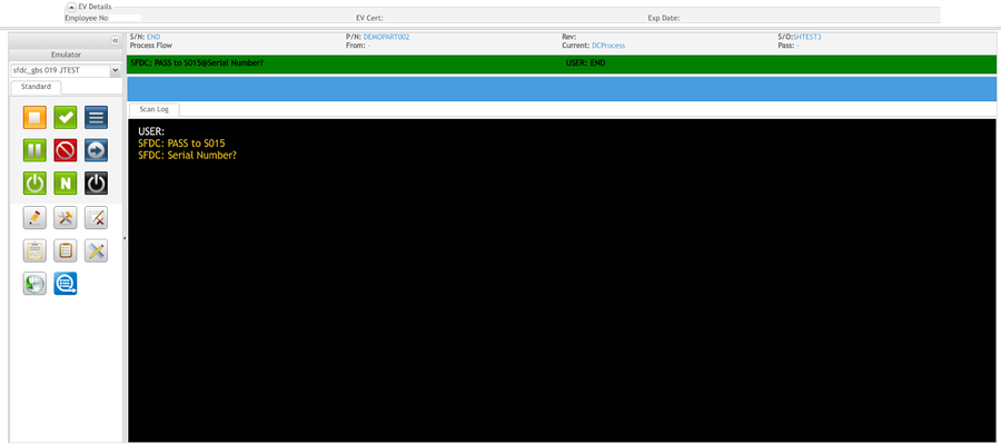
1. To access the Data Collector page, navigate to Production > Data Collector.
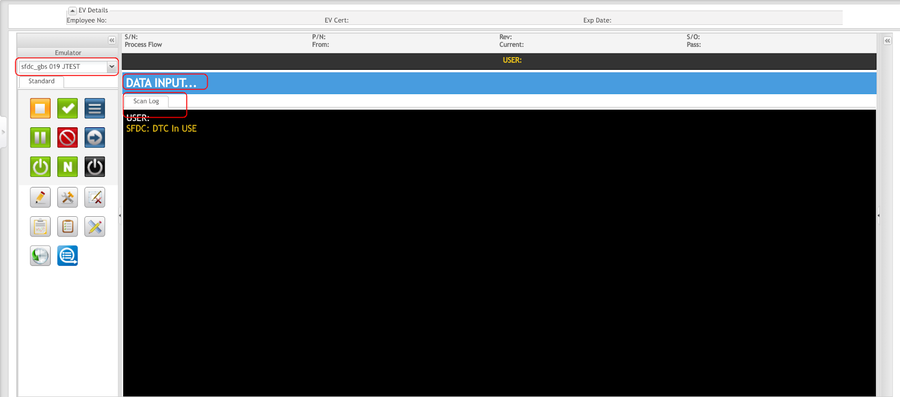
Figure 1: Data Collector Main Page
Station ID- Station ID is a label used to define device IDs used at a particular workstation. Its purpose is to group and limit the available device IDs for any defined workstation. By limiting the available device numbers at a workstation, eliminates confusion to the operator, and prevents issues where two users might be trying to access the same device at the same time.
Note: If this is the user's first time accessing the portlet, a window will display asking for a Station ID. The user must enter a valid Station ID that has been activated in Device Maintenance and select OK to continue.
Note: If the login Station ID is changed or deactivated under Device Maintenance, this window will pop up again even if it is not the user's first time accessing the portlet.
If this is not the user's first time accessing the page, when Data Collector is selected, the DC Emulator screen will be displayed.
Employee Validation
Employee Validation controls the ability of a user to scan a part number (serial) at a particular process. Also configured in Employee Validation are certificates of inspection. If a certificate has not been defined for a process, then a user can scan. However, a certificate and class must be configured for a process in order to control scanning at that process. EV data will only be displayed if the selected device number has a controlled process associated with it. If a certificate is defined for a specific serial at that process, then data for that part number will be displayed.
Located at the top of the Data Collector main screen is an EV Details information box. This expandable section lists the Employee Number, Employee Validation Certificate, and Expiration Date if defined.
Figure 2: EV Details
- Employee Number: Displays the Employee Number of the user that is logged into the system.
- EV Cert: The certificate is tied to the scanned serial.
- Exp Date: The expiration date of the scanned serial.
Note: If a serial is scanned on a non-configured EV, there is no certificate to find, therefore, no information will be displayed.
Production Scanning
The main Data Collector screen contains various items that are pertinent to the device scanning.
Figure 3: Serial Scanning
- Unit ID: This is a list of all configured, active Unit IDs for a defined Station ID. Unit ID = Shop Floor ID + Device ID + Description, which requires pre-configurations in Device Maintenance. Select one from the drop-down list.
Note: Only select the Unit ID that applies to the job function.
- Scan Log (black area): This is a read-only field displaying SFDC scanning messages, including both user inputs and system prompts.
- Data Input (blue area): Scan or manually input text into this field.
Note: The Input Data field provides visual feedback for the scanned serial by displaying the following colors:
- Green= Pass
- Yellow= Error
- Red= Fail
- Black= No Error
Figure 4: Serial Information
- S/N: This is a read-only field displaying the currently scanned S/N.
- P/N: This is a read-only field displaying the Part Number for the currently scanned S/N.
- Rev: This is a read-only field displaying the current revision for the scanned S/N.
- S/O: This is a read-only field displaying the shop order for the scanned S/N.
Figure 5: Process Flow
- From: The Process name from which the scanned S/N came from.
- Current: The Process name in which the S/N is currently scanned.
- Pass: The Process name to which the scanned S/N will pass to.
The Standard Tab contains the following functions to aid in the scanning and defect recording processes:
 RELEASE- Releases a scanned unit at its station. The unit remains at this station until it is passed, failed, or moved.
 NO- Sent to SFDC as a response to yes/no prompts.
 NEXT- Skips adding of the prompted attribute or component and proceeds to the next one or goes on to the Menu Selection Prompt.
 RESET- Exits the current transaction and returns back to Employee prompt without passing the unit to the next station. This will not back out any transactions already processed, such as components added or defects recorded.
 N/A- Sent to SFDC as a response to yes/no prompts.
 LOGOUT- Logs the user out of the current station.
 Record Defect- Allows the user to record defects against the serial number.
 Repair Defect- This allows the user to repair defects recorded against the serial number.
 Unit Defects- Lists all recorded and repaired defects for the serial number.
  Top Defects- Lists the top five defects for the serial number.
 Repair Notes- This allows the user to view, add, edit, or delete repair notes attached to repaired defect codes.
 Measurement- Displays parametric data captured via Measurement.
 Unit History- Displays the complete history of a particular serial number.
 DTC In-Use- Frees up the device by logging out the previous user if that user forgot to logout from the device.
Serial Scanning
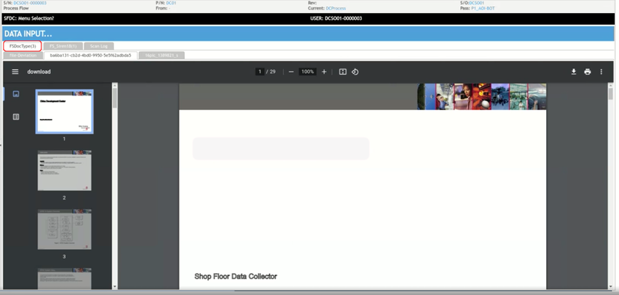
Upon a valid serial scanning, all documents that have been pre-configured for the scanned serial will be displayed in the Doc View panel.
- Files will be grouped by the document type in tabs.
- Select the document type tab to view documents.
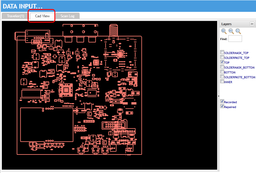
- CAD View is a tab tailored for the displaying of CAD files.
View Document
After a successful serial scan, any documents that are configured in Upload Agile Document/Upload Local Document will be displayed. If there are multiple documents, the default document of the default document type will always be displayed. The remaining documents will be placed in tabs for seamless navigation.
1. Select one Unit ID from the drop-down list labeled Select Unit ID.
2. Scan or input a serial number in theData Input field.
3. The default document will display in the display window.
Figure 6: Document Display
4. If there are multiple documents mapped to the scanned serial, the subsequent documents will be available to view from tabs located above the display window. To select a different document, choose which document to view by selecting the appropriate document tab.
CAD View
After a successful serial scan, the CAD view of the device will display in a tab located below the Data Input field. The CAD view is a computer-aided drawing of the device that is presented to the user for reference. Multiple layers are available to view through the navigational panel located to the right of the CAD.
Note: A CAD drawing must be configured at the scanning process to be displayed.
1. Select one Unit ID from the drop-down list labeled Select Unit ID.
2. Scan or input a serial number in the Data Input field.
3. The CAD will be available in the tab panel. Select the CAD tab to view the device.
Note: The user can search for a component in a CAD by the reference designator. The reference designator that is specified as part of a recorded defect or repair is automatically displayed by using recorded or repaired switches.
Figure 7: CAD View
Record & Repair Defect
The record and repair defects functions allow for:
- Advanced defect recording with PTS integration for component validation. An entered reference designator is validated against the BOM in PTS, in order to ensure that the component exists.
- Advanced repair recording with PTS integration for validation of replacement component validation. Based upon the reference designator, the component is validated against the BOM in PTS. A Material Barcode field is included in order to validate the replacement component, ensuring the correct part number, manufacturer, valid data code, etc. are used.
- Web service link to SFDC Measurement for displaying parametric records for an entered serial number. The Measurement server must be configured in MES Portal in order for records to be accessed. All available records found for the scanned serial number are displayed.
- Top 5 defects and repairs based upon the part number of the scanned serial number. The display is based upon defects/repairs entered by the GUI in the Portal. Historical data from SFDC is not used. Chart display or list of defect/repair codes with description.
- Tech Notes field for the recording of troubleshooting information.
Note: In order to work with this functionality, PTS integration must be properly configured. If PTS integration is not set up, the reference designators will not be validated.
Record Defect
The user can record defects against a serial number to document marginal attributes, monitor yields, and create reports containing current and historical yields.
1. To record a defect against a serial number, select one Unit ID from the drop-down list labeled Select Unit ID.
2. Scan or input a serial number in theData Input field.
3. Select the Record Defect icon from the Standard panel.
Figure 8: Record Defect
The Record Defect form displays. Enter the following information:
- The Defect Code field will display a drop-down list of available defect codes. The list filters to matching codes as characters are entered into the field. All available defect codes are listed unless a pre-defined list is configured in the Defect GUI module in MES.
- The Reference Designator field is used to enter a reference designator of a failed component. This is the same as what would be entered when recording a defect at a standard data collector using the RCDFC or customized Record Defects command.
- The Pin 1 / Pin 2 fields are used to enter the pin numbers of a defective component. The function is the same as what would be entered when recording a defect at a standard data collector using the RCDFC or customized Record Defects command.
- The Quantity field is used to enter the total number of defects for the entered defect code. If a different defect is present, then a separate defect should be recorded using the correct defect code and information. The function is the same as what would be entered when recording a defect at a standard data collector using the RCDFC or customized Record Defects command.
- The Side field is used to enter 0 or 1 for the side of the assembly. This is the same as the Surface field when recording a defect at a standard data collector using the RCDFC or customized Record Defects command.
- The Repair check box is selected when the entered defect is being repaired at the same time the defect is being recorded. Selecting it will cause the pane to expand and all the fields found under the Repair tab are displayed.
4. Select Record to record the defect without repairing it. Select Reset to clear all fields. Select Close to exit.
Repair Defect
The user can repair recorded defects while recording them, or at a later date using the repair defect function.
Repair Defect While Recording:
1. To repair a defect while recording, select the Repair option located below the record defect form.
2. Enter the Material Barcode, Repair Code, and/or Repair Note and then select Record.
Note: The Repair Code is the only required field.
Figure 9: Repair Defect While Recording
Note: The user can access defects to repair after recording by selecting the Repair Defect or Unit Defects icons.
Repair Defect Icon
1. To repair a defect after recording, select the Repair Defect icon.
2. Enter the Reference Designator, if known. This will limit the Defect Code drop-down selections to the specific defect code to repair.
3. If the reference designator is unknown, select the defect code from the list in the Defect Code drop-down box provided.
Note: The Defect Code field is mandatory but the Reference Designator field is not.
4. After selecting the defect to repair, enter the Material Barcode, Repair Code, and/or Repair Note and then select Record.
Note: The Repair Code is the only required field.
Figure 10: Repair Defect
Unit Defects
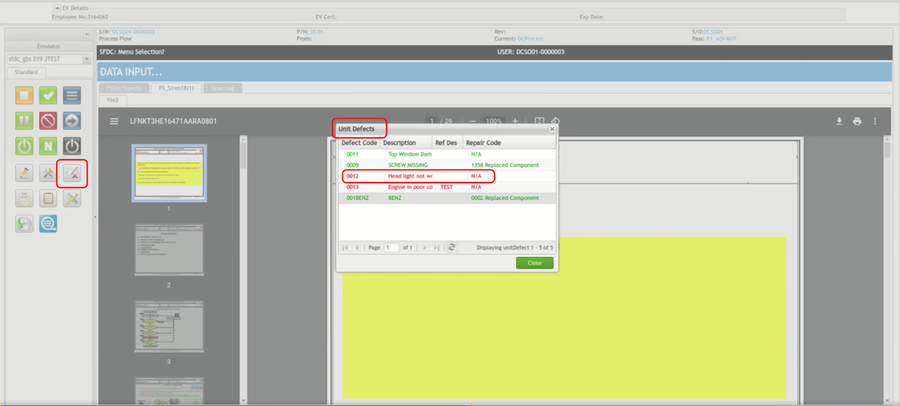
The Unit Defects function lists all recorded and repaired defects. Recorded defects are displayed in red, repaired defects are displayed in green. The user can repair defects from the Unit Defects screen by double-clicking on any red defect listed.
1. To repair a defect from the Unit Defects screen, select the Unit Defects icon.
2. The unit defects screen displays all defects that have been recorded and repaired for that serial number. Select a red defect by double-clicking on it.
Figure 11: Unit Defects
3. The repair form displays with the reference designator and defect code pre-populated.
4. Select the repair code and enter the material barcode or Repair note if desired.
5. Select Record to repair the defect.
Figure 12: Repair Defect
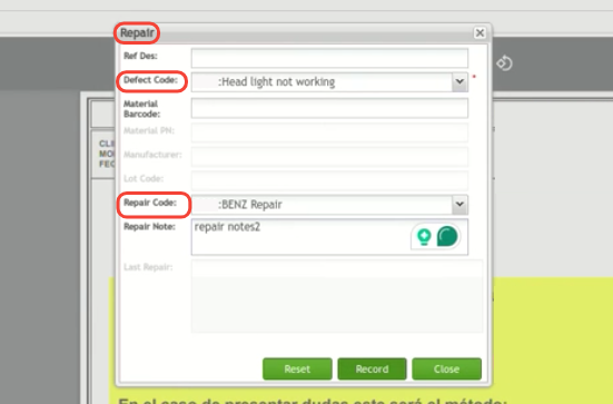
The defect will now appear in green on the Unit Defects screen.
After repairing all defects, to pass a serial number to the next location in the route, select END. If all actions have been correctly completed, the unit will pass to the next location, if not, a red box displays.
Figure 13: PASS to
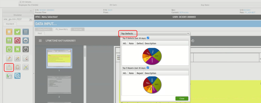
Top Defects
The Top Defects function lists the top five defects for the previous 30-day cycle for a particular part number.
1. To list the top five defects, select one Unit ID from the drop-down list labeled Select Unit ID.
2. Scan or input a serial number in the Data Input field.
3. Select the Top Defects icon located in the standard panel.
4. The Top Defects form displays. The default view is a pie chart with data from the last 30 days.
Figure 14: Top Defects
5. To view the defect code descriptions, select the box located above the pie chart.
6. Select Close to exit after viewing.
Repair Notes
The Repair Notes function allows the user to view, add, edit, or delete repair notes attached to repaired defect codes.
1. To access Repair Notes, select one Unit ID from the drop-down list labeled Select Unit ID.
2. Scan or input a serial number in the Data Input field.
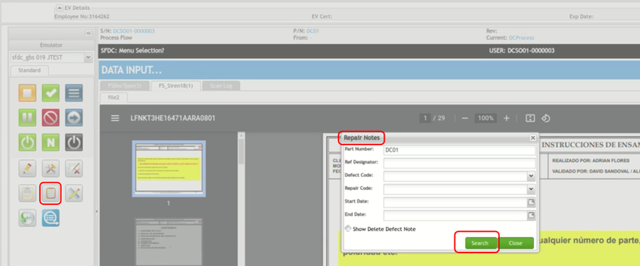
3. Select the Repair Notes icon from the standard panel.
4. The Repair Notes search form displays.
Figure 15: Search Repair Notes
5. The Part Number is pre-populated according to the serial scan. If the reference designator is known, the user can enter it to limit the defect code selections.
6. Select a defect code from the Defect Code drop-down box.
7. Select the repair code associated with the defect code from the Repair Code drop-down box.
8. The user can set date parameters by entering a Start Date and anEnd Date in the fields provided to narrow the search field.
9. Select Show Delete Defect Note, if deletion is desired.
10. Select Search to display the repair notes for that particular defect code.
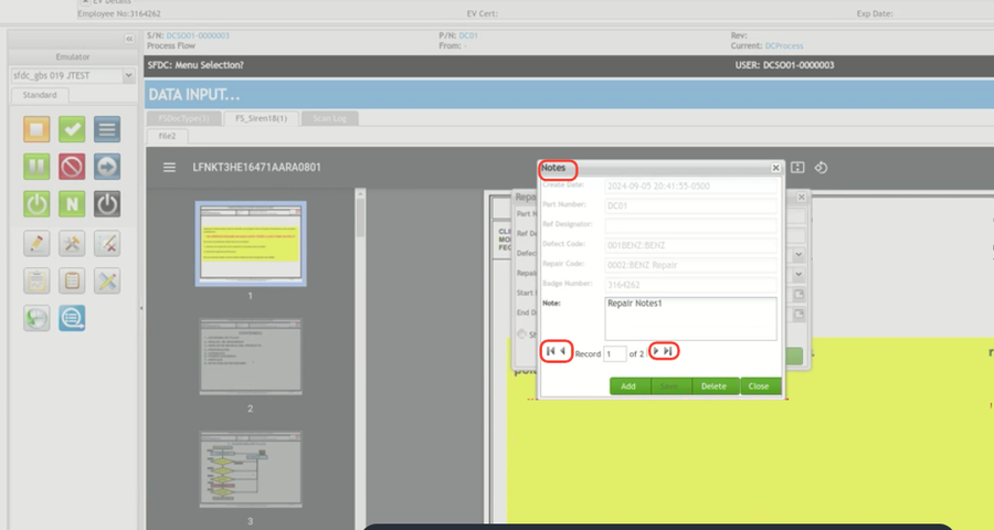
Figure 16: Repair Notes
The Create Date, Part Number, Reference Designator, Defect Code, Repair Code, and Badge Number fields are greyed out and unavailable to edit.
11. To edit the current repair note, type directly into the Note field.
12. To add a repair note select Add and enter repair note. Select Save to confirm.
13. To delete a repair note, select Delete located below the Note field.
Once multiple notes have been added, they are available to view on pages that can be navigated with arrows located below the Note field.
Measurement
The Measurement icon displays parametric data captured via Measurement.
Note: SFDC must be configured to communicate with the measurement server in order to get parametric data.
(This function is currently under construction.)
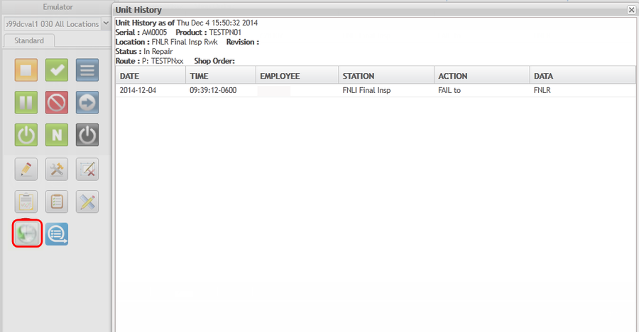
Unit History
The Unit History icon displays the complete history of a particular serial number. The information displayed includes:
- Date
- Time
- Employee
- Station
- Action (Create Record, PASS to, Defect Sequence, Repair Defect)
- Data
1. To view the unit's history, select the Unit History icon.
2. After viewing, select Close to exit.
Figure 17: Unit History

