Difference between revisions of "42Q-MES0184-IIoT Configuration"
| Line 536: | Line 536: | ||
| | ||
| − | == <span class="mw-headline" id="DataIngestion"><span class="mw-headline" id="DataIngestion"><span class="mw-headline" id="DataIngestion"><span class="mw-headline" id="DataIngestion"><span class="mw-headline" id="DataIngestion"><span class="mw-headline" id="DataIngestion"><span class="mw-headline" id="DataIngestion"><span class="mw-headline" id="DataIngestion"><span class="mw-headline" id="DataIngestion"><span class="mw-headline" id="DataIngestion"><span class="mw-headline" id="DataIngestion"><span class="mw-headline" id="DataIngestion"><span class="mw-headline" id="DataIngestion"><span class="mw-headline" id="DataIngestion"><span class="mw-headline" id="DataIngestion"><span class="mw-headline" id="DataIngestion"><span class="mw-headline" id="DataIngestion"><span class="mw-headline" id="DataIngestion"><span class="mw-headline" id="DataIngestion"><span class="mw-headline" id="DataIngestion"><span class="mw-headline" id="DataIngestion"><span class="mw-headline" id="DataIngestion"><span class="mw-headline" id="DataIngestion"><span class="mw-headline" id="DataIngestion"><span class="mw-headline" id="DataIngestion"><span class="mw-headline" id="DataIngestion"><span class="mw-headline" id="DataIngestion">DataIngestion</span></span></span></span></span></span></span></span></span></span></span></span></span></span></span></span></span></span></span></span></span></span></span></span></span></span></span> == | + | |
| + | == <span class="mw-headline" id="DataIngestion"><span class="mw-headline" id="DataIngestion"><span class="mw-headline" id="DataIngestion"><span class="mw-headline" id="DataIngestion"><span class="mw-headline" id="DataIngestion"><span class="mw-headline" id="DataIngestion"><span class="mw-headline" id="DataIngestion"><span class="mw-headline" id="DataIngestion"><span class="mw-headline" id="DataIngestion"><span class="mw-headline" id="DataIngestion"><span class="mw-headline" id="DataIngestion"><span class="mw-headline" id="DataIngestion"><span class="mw-headline" id="DataIngestion"><span class="mw-headline" id="DataIngestion"><span class="mw-headline" id="DataIngestion"><span class="mw-headline" id="DataIngestion"><span class="mw-headline" id="DataIngestion"><span class="mw-headline" id="DataIngestion"><span class="mw-headline" id="DataIngestion"><span class="mw-headline" id="DataIngestion"><span class="mw-headline" id="DataIngestion"><span class="mw-headline" id="DataIngestion"><span class="mw-headline" id="DataIngestion"><span class="mw-headline" id="DataIngestion"><span class="mw-headline" id="DataIngestion"><span class="mw-headline" id="DataIngestion"><span class="mw-headline" id="DataIngestion"><span class="mw-headline" id="DataIngestion"><span class="mw-headline" id="DataIngestion">DataIngestion</span></span></span></span></span></span></span></span></span></span></span></span></span></span></span></span></span></span></span></span></span></span></span></span></span></span></span></span></span> == | ||
Please follow the steps below to create a 42Q Cloud Data Ingestion Edge Device in 42Q: | Please follow the steps below to create a 42Q Cloud Data Ingestion Edge Device in 42Q: | ||
| Line 563: | Line 564: | ||
| | ||
<ol start="13"> | <ol start="13"> | ||
| − | <li> | + | <li>'''Select '''the'''Edge Device, '''and'''select '''the'''Edit button.'''</li> |
| + | <li>'''Select '''the'''CLIENT DEVICES tab.'''</li> | ||
| + | <li>'''Select ASSOCIATE CLIENT DEVICES.'''</li> | ||
</ol> | </ol> | ||
| − | + | <br/> '''Figure 33: CLIENT DEVICES TAB''' | |
| − | |||
| − | <br/> '''Figure | ||
| − | |||
| − | |||
| − | + | [[File:DSS Client Devices Tab.png|900px|DSS Client Devices Tab.png]] | |
| − | |||
| − | |||
| − | |||
| − | |||
| − | |||
| − | |||
| − | |||
| − | |||
| − | |||
| − | [[File: | ||
| | ||
<ol start="16"> | <ol start="16"> | ||
| − | <li>'''Enter''' the name of the '''Client Device''' to be created.</li> | + | <li>'''Enter '''the name of the'''Client Device''' to be created'''.'''</li> |
</ol> | </ol> | ||
| − | <u>'''Note | + | <u>'''Note'''</u>: The name can be up to 128 characters. Valid characters: a-z, A-Z, 0-9, underscore (_), and hyphen (-). |
| − | |||
| − | |||
<ol start="17"> | <ol start="17"> | ||
| − | <li>'''Select''' ''' | + | <li>'''Select SAVE'''.</li> |
| + | <li>'''Select''' the '''Download''' icon to download the '''Client Device ZIP file'''.</li> | ||
| + | <li>'''Right-click''' on the '''ZIP file'''.</li> | ||
| + | <li>Select '''Extract Here''' to unzip the file.</li> | ||
</ol> | </ol> | ||
| | ||
| − | '''Figure | + | '''Figure 34: Creating a Client Device''' |
[[File:Figure 19- Creating a Client Device1.png|border|DSS Creating a Client Device.png]] | [[File:Figure 19- Creating a Client Device1.png|border|DSS Creating a Client Device.png]] | ||
| − | + | <br/> '''Figure 35: Client Device Folder''' | |
| − | |||
| − | |||
| − | |||
| − | |||
| − | |||
| − | |||
| − | |||
| − | |||
| − | <br/> '''Figure | ||
| − | [[File: | + | [[File:IIoT Client Device Folder.png|900px|IIoT Client Device Folder.png]] |
| | ||
| Line 624: | Line 605: | ||
| | ||
| − | <br/> '''Figure | + | <br/> '''Figure 36: Data To Be Modified''' |
| − | [[File: | + | [[File:IIoT Data To Be Modified.png|900px|IIoT Data To Be Modified.png]] |
| | ||
| Line 634: | Line 615: | ||
</ol> | </ol> | ||
| − | + | <br/> '''Figure 37: Result Of Executing The MqttTest.py File''' | |
| − | |||
| − | <br/> '''Figure | ||
[[File:DSS Result Of Executing The MqttTest.py File.png|900px|DSS Result Of Executing The MqttTest.py File.png]] | [[File:DSS Result Of Executing The MqttTest.py File.png|900px|DSS Result Of Executing The MqttTest.py File.png]] | ||
| Line 647: | Line 626: | ||
| | ||
| − | + | '''Figure 38: Successful MqttTest.py Running Logs''' | |
| − | |||
| − | '''Figure | ||
[[File:DSS Successful MqttTest.py Running Logs.png|800px|DSS Successful MqttTest.py Running Logs.png]] | [[File:DSS Successful MqttTest.py Running Logs.png|800px|DSS Successful MqttTest.py Running Logs.png]] | ||
| − | + | | |
<u>'''Note:'''</u> If the message from the previous image is printed in your local log, the function has succeeded. | <u>'''Note:'''</u> If the message from the previous image is printed in your local log, the function has succeeded. | ||
| − | |||
| − | |||
| | ||
Revision as of 17:14, 8 October 2024
42Q Home > IIoT > Device Self Service
Contents
Introduction
The concept of GGC stands for “Green Grass Computer”, the word: “Computer” also refers to any kind of device. This document will teach users how to configure, install, and deploy a GGC, as well as create and set up a Device Self-Service for establishing a connection between the computer (device) and the 42Q portal to send data (payloads).
Prerequisites
- Only Linux is supported for the computer or device to install the Green Grass Core. The related shell scripts and test code only work on Linux systems (Windows is not currently supported).
- Python 3.8 or higher must be installed and configured to run the test code.
Operating System and Software Requirements
- Linux kernel version 4.4 or later (Ubuntu 20.04 and CentOS 8.5).
- Java Runtime Environment (JRE) version 11 or greater (included in the installation script).
- Python version 3.8 for functions that use the Python 3.8 runtime (included in the installation script).
Cgroups Requirements
The AWS IoT Greengrass Core software currently only supports Cgroups v1, not v2. In order to satisfy AWS Greengrass Core dependencies as stated in the official documentation "Setting up AWS IoT Greengrass core devices" (Setting up AWS IoT Greengrass core devices - AWS IoT Greengrass ), the system should be configured with the following Linux kernel parameters and restarted:
To enable these Cgroups options, boot the device using the following Linux kernel parameters:
Step 1: sudo vi /etc/default/grub
Find GRUB_CMDLINE_LINUX, and add the following command to it.
- For Centos 8.5
cgroup_enable=memory cgroup_memory=1 systemd.unified_cgroup_hierarchy=0
Figure 1: Command
- For Ubuntu 22.04
cgroup_enable=memory cgroup_memory=1 systemd.unified_cgroup_hierarchy=false
Step 2: Enter the command: sudo update-grub
Step 3: Restart the system. sudo reboot
Then check the Cgroup, response tmpfs is right.
root@:~# stat -fc %T /sys/fs/cgroup/tmpfs
Adjusting Cgroup configuration
- Edit /etc/default/grub - Find the line that starts with "GRUB_CMDLINE_LINUX=" and append or change the following values: cgroup_enable=memory cgroup_memory=1 systemd.unified_cgroup_hierarchy=false - Save the file
- Apply the configuration change by running: update-grub
- Restart the system
- Verify that the Cgroup configuration has been set to v1 by running the following command and ensuring that the response is "tmpfs": stat -fc %T /sys/fs/cgroup/;
Network requirements
The Green Grass Core device must be able to access the following endpoints through specific ports:
- https://www.amazontrust.com/repository/AmazonRootCA1.pem.
- https://d2s8p88vqu9w66.cloudfront.net/releases/greengrass-2.12.6.zip.
- greengrass-ats.iot.us-east-1.amazonaws.com. Ports: 443.
- .iot.us-east-1.amazonaws.com. Ports: 443.
- .credentials.iot.us-east-1.amazonaws.com. Ports: 443.
For more details on what traffic needs to be authorized and why, please visit the official AWS documentation.
Functional Description
There are three different functional components: CloudPrinting, MachineInterface, FileUploader, and DataIngestion.
To access the Edge Devices portlet, navigate to: Shop Floor Control > Configuration > IIoT Configuration > Edge Devices.
Figure 2: Accessing Edge Devices

Figure 3: Edge Devices Functions
- Users can query the list of all devices by Edge Device Name or Functionality Name.
- Users can create a new Edge Device.
- Users can activate or deactivate the certificate status.
- Users can view or edit the details of the edge device and its logs.
- Users can download the Edge device software.
- Users can Upgrade this edge device with more features.
- Users can get all functional components through this button when no functional components are deployed on their local core device.
- Users can Delete the edge device.
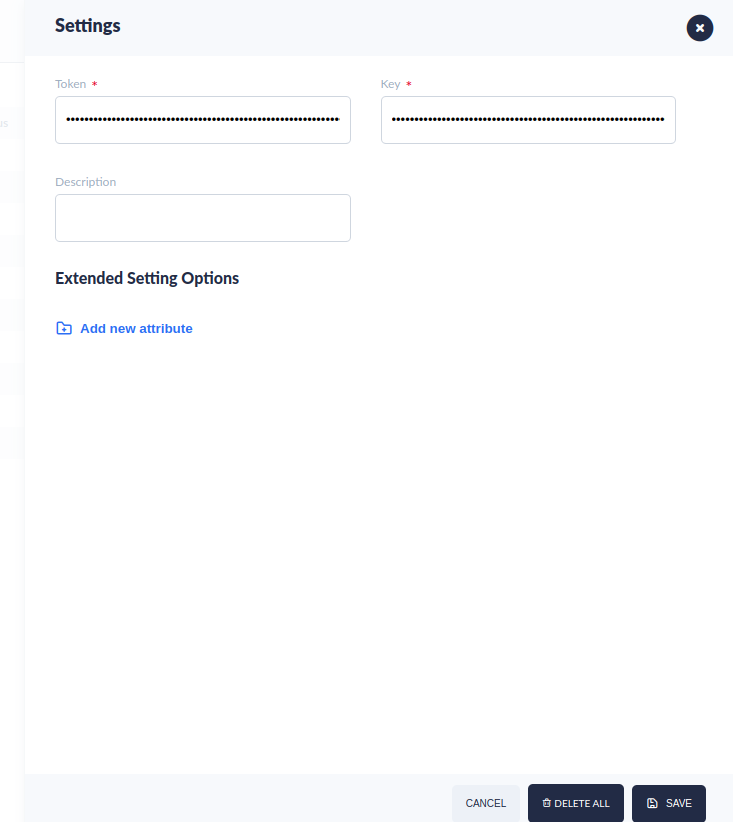
- Settings allow users to configure or get the palindrome information which can be used by the functionalities in the IIoT application.
Figure 4: Settings
Edit Edge Device
When the status of the Edge Device is "Healthy", select the Edit button to enter the Edge Device information. The users can add functionality, associated client devices, and view its logs.
Figure 5: Edit Button
Components
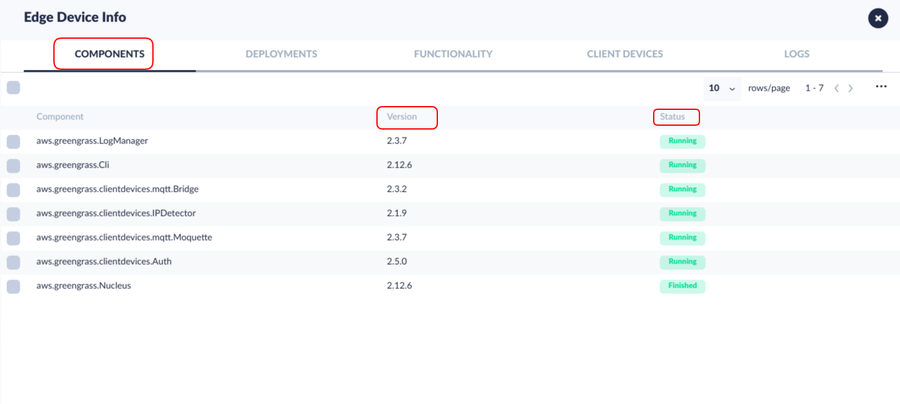
The components tab allows users to view all components installed in this Edge device. It displays the version and status of the installed components.
Figure 6: Components Tab
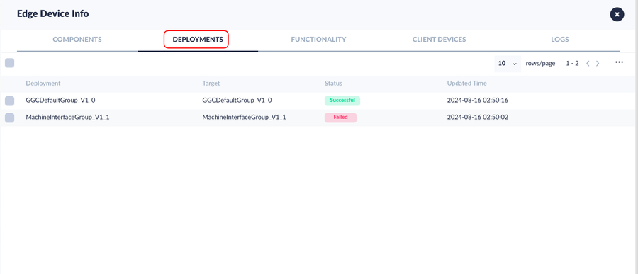
Deployments
The Deployments tab allows users to view all the Functionality statuses installed in this Edge device.
Functionality
- Select the FUNCTIONALITY tab.
Figure 8: Functionality tab
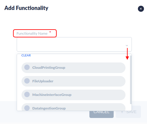
- Select theADD FUNCTIONALITY.
Figure 9: Add Functionality
- Users can edit or delete the functionality. Each functionality supports two versions (1.0 and 1.1) and users can switch between these versions (from 1.0 to 1.1 or from 1.1 to 1.0).
Figure 10: Edit Functionality Version
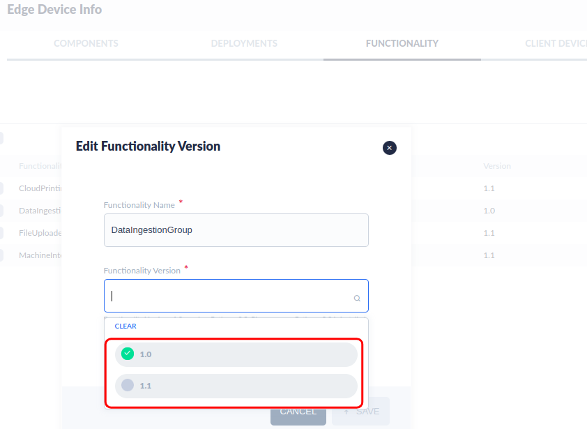
Note: An Edge device will install Python 3.11 by default however it supports both Python 3.8 and Python 3.11. A single functionality can only be set to either Version 1.0 or Version 1.1. Ensure that the appropriate Python version is installed locally:
- Functionality Version 1.0 requires Python 3.8.
- Functionality Version 1.1 requires Python 3.11.
Users can execute the following two new scripts in the terminal to install Python 3.11 and Python 3.8.
- sudo sh Install_Python3.8.sh
- sudo sh Install_Python3.11.sh
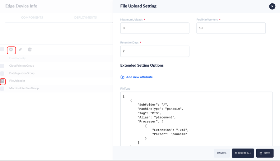
- Users can use the settings option in the Edge device Functionality tab to manage the functionality configurations.
Figure 12: File Upload Setting
Client Devices
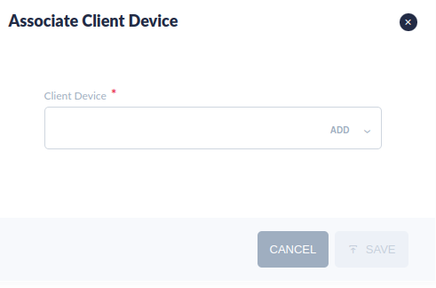
- Select the CLIENT DEVICES tab.
- Select ASSOCIATE CLIENT DEVICES.
Figure 13: Client Devices Tab
- Enter the name of the Client Device to be created.
Note: The name can be up to 128 characters. Valid characters: a-z, A-Z, 0-9, underscore (_), and hyphen (-).
- Select SAVE.
- Users can activate or deactivate the certificate status.
- The Client Device tab supports batch downloads and deletions.
Figure 14: Creating a Client Device
Assets
The Asset is used to enable the 42Q/Machine communication feature. For more information, refer to How to Configure a bidirectional event-link communication channel between IT and OT.
- Select the Assets icon to manage the assets that integrated the shadows/machines.
- Users can Select and Delete multiple assets at once.
Figure 15: Manage Assets
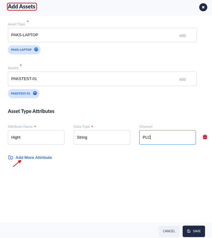
- At the Assets page, select ADD ASSET.
Figure 16: Add Assets
- Select the Asset Type, Assets, and add the Attributes.
- Asset Type: The users can select the Asset Type that already exists, or create a new asset Type by selecting the Add button.
- Assets: The users can select the Assets that already exist, or create a new asset by selecting the Add button.
- Attributes: Add the attributes of the asset. Note: The attributes will be associated with the Asset Type. One Asset Type can have multiple attributes. The channels for this asset type should have the same value. Channel: Optional, Each protocol or driver used in a server project is called a channel. A server project may consist of many channels with the same communications driver or with unique communications drivers. A channel acts as the basic building block of an OPC link. This group is used to specify general channel properties, such as the identification attributes and operating mode. The channel in the attribute is optional, but If the customer needs to use Kepware to change/update tag value from MQTT messages, you would need to enter the channel(same as the channel in Kepware) when defining the asset type.
- Select SAVE, then close the assets page to return to the Edge Device Info page.
Logs
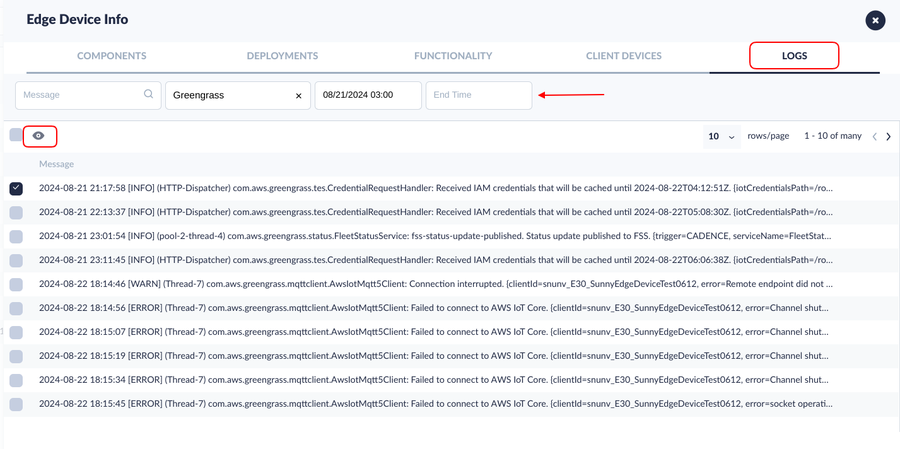
- Select the Logs tab to view GreenGlass logs for each Edge Device and for various functionalities, such as Data Ingestion, Cloud Printing, Machine Interface, and File Uploader.
- Users can filter the logs by Message, Functionality Nam, Start Time, and End Time.
Figure 17: Logs Tab
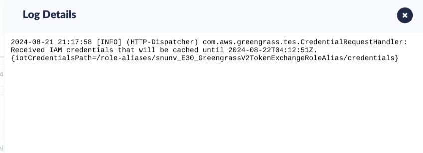
- Select the required log and log details option to see the detailed information of the log.
Figure 18: Log Details
Install 42Q Edge Software
CloudPrinting
Figure 19: Cloud Printing
Please follow the steps below to create a 42Q Cloud Printing Edge Device in 42Q:
- Navigate to: Shop Floor Control > Configuration > IIoT Configuration > Edge Devices.
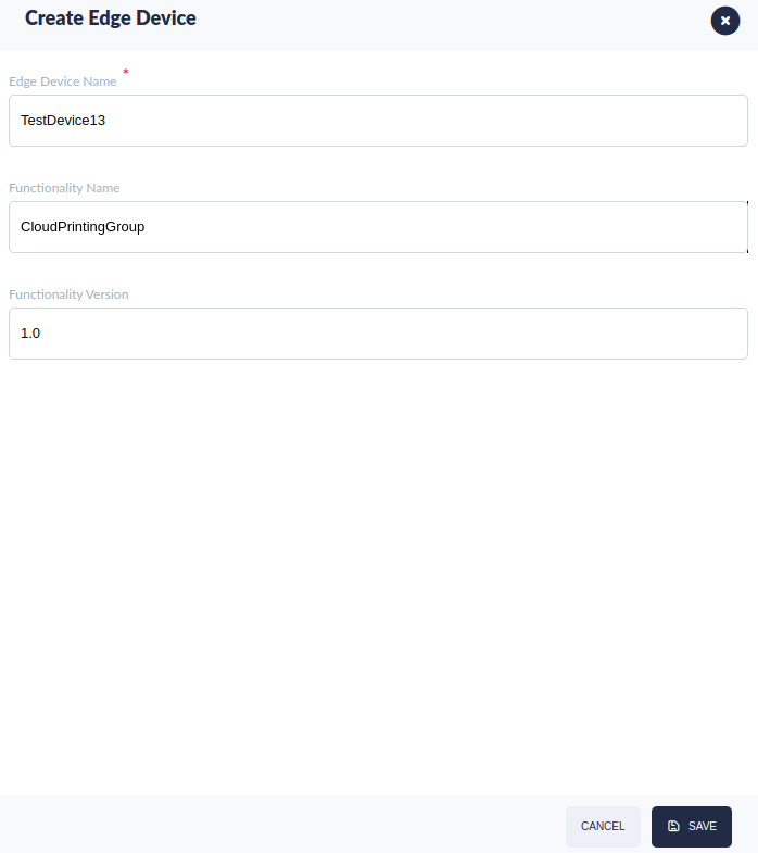
- Select CREATE EDGE DEVICE to create a new Green Grass Core.
Figure 20: CREATE EDGE DEVICE Button
- Enter the Edge Device Name of the Green Grass Core. The name can be up to 128 characters. Valid characters are: a-z, A-Z, 0-9, colon (:), underscore (_), and hyphen (-).
- Select the Group Name as CloudPrintingGroup.
Note: Once the Functionality Name is selected, the Functionality Version will automatically be selected.
Figure 21: Create Edge Device Form
- Select the checkbox next to the desired Edge Device.
- Select the Download icon to download the Edge Device ZIP file.
Figure 22: Downloading The Files
- Right-click on the ZIP file.
- Select Extract Here to unzip the file.
- Open the Terminal.
- Enter the command: sudo su, and then press Enter.
- Enter the root user’s password, and then press Enter.
Note: If the word: root@ appears before the computer’s username as in the image below, it means that you are logged in as a root user.
Figure 23: User Logged In as a Root User
- Enter the next command: sh ggcV2.sh, and then press Enter.
Note: After the script is installed successfully, users can navigate to the local device’s path: /greengrass/v2 to check the installed folder; logs are contained in the path: /greengrass/v2/logs.
Figure 24: Edge Device Folder
Testing Label Printing Function Using Label Engine Screens
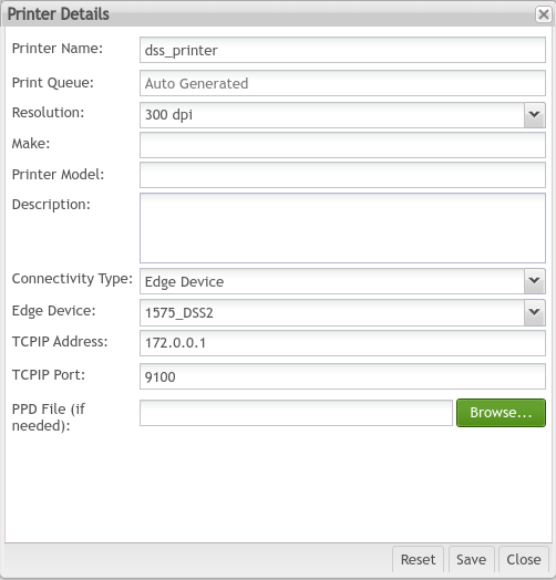
- Navigate to: Administration > Label Engine Admin > Printer.
- Select Add.
- Enter the Printer Name.
- Select the Resolution from the drop-down list.
- Select the Connectivity Type as Edge Device.
Figure 26: Entering The Printer Details
Note: The TCP IP Address should be the address of the printer or start a TCP Server as a simulator by executing the next command in the Terminal:
sudo -H -u ggc_user python3.8 tcpServer.py or sudo -H -u ggc_user python3.11 tcpServer.py. The FiletcpServer.py be included in the Edge Device ZIP file.
- Navigate to: Production > Label Engine Labels > LE Labels.
- Search for the label called “entry”, which will print whatever "Entry" value is passed.
- Select the checkbox next to the printer name.
- Select Print.
Figure 27: Print Button
- Select the Printer Name previously created.
- Enter a value in the Entry field.
- Select Test Print.
Figure 28: Entering Test Print Data
- Open the Terminal.
- Navigate to the local device’s path: /greengrass/v2/logs.
- Enter the next command: tail -f {envide}_CloudPrinting.log. After that, a message will be received to confirm the successful testing.
Figure 29: Successful Testing Message
MachineInterface
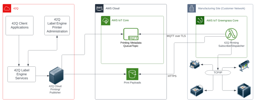
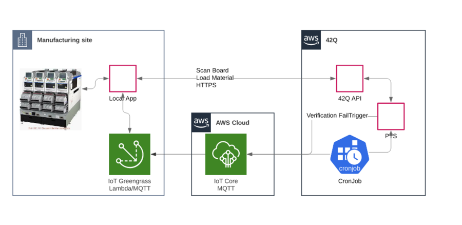
This function is used for sending commands to machines from the cloud.
Below there is an example of stopping a machine when the server finds MSD material expired.
Figure 30: Server Stopping A Machine Due To Material Expired Diagram
The diagram above is divided into three steps:
- Install an Edge Device on a server in the plant.
- The plant creates a new local application that can communicate with the Edge Device by TCP and also can send commands to machines.
- The Cloud application will send commands to the Edge Device, then the Edge Device will forward the message to the local application through TCP/IP.
Please follow the steps below to create a 42Q Cloud Machine Interface Edge Device in 42Q:
- Navigate to: Shop Floor Control > Configuration > IIoT Configuration > Edge Devices.
- Select CREATE EDGE DEVICE to create a new Green Grass Core.
- Enter the Edge Device Name of the Green Grass Core. The name can be up to 128 characters. Valid characters are: a-z, A-Z, 0-9, colon (:), underscore (_), and hyphen (-).
- Select the Group Name as MachineInterfaceGroup.
Note: After selecting the Group Name, the Group Version will automatically be selected.
- Select the checkbox next to the desired Edge Device.
- Select the Download icon to download the ZIP file.
- Right-click on the ZIP file.
- Select Extract Here to unzip the file.
- Open the Terminal.
- Enter the command: sudo su, and then press Enter.
- Enter the root user’s password, and then press Enter.
- Navigate to the extract folder by using the command: cd {folder path}.
- Enter the next command: sh ggcV2.sh, and then press Enter.
Note: After the script is installed successfully, users can navigate to the computer’s path: /greengrass/v2 to check the installed folder; logs are contained in the path: /greengrass/v2/logs.
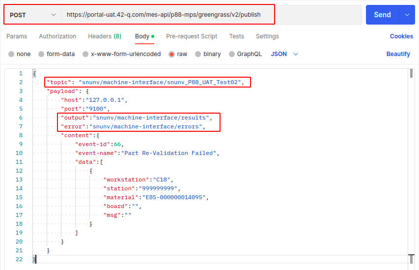
- Open Postman to test its functionality.
- Select POST as HTTP Method.
- Enter the URL.
- Enter the Topic.
- Enter the Output.
- Enter the Error.
Data nomenclature example:
URL: https://portal-uat.42-q.com/mes-api/[SiteName]/greengrass/v2/publish
Topic: [Envide]/machine-interface/[Envide]_[Edge device name]
Output: [Envide]/machine-interface/results
Error: [Envide]/machine-interface/errors
Figure 31: Sending The Payload Using Postman
- Open the Terminal.
- Navigate to the local device’s path: /greengrass/v2/log to view the logs.
Figure 32: Successful Payload Sending Logs
Note: If the message from the previous image is printed in your local log, the function has succeeded.
Adding the corresponding configuration for PTS allows PTS to send messages to Edge Device.
DataIngestion
Please follow the steps below to create a 42Q Cloud Data Ingestion Edge Device in 42Q:
- Navigate to: Shop Floor Control > Configuration > IIoT Configuration > Edge Devices.
- Select CREATE EDGE DEVICE to create a new Green Grass Core.
- Enter the Edge Device Name of the Green Grass Core. The name can be up to 128 characters. Valid characters are: a-z, A-Z, 0-9, colon (:), underscore (_), and hyphen (-).
- Select the Group Name as DataIngestionGroup.
Note: After selecting the Group Name, the Group Version will automatically be selected.
- Select the checkbox next to the desired Edge Device.
- Select the Download icon to download the ZIP file.
- Right-click on the ZIP file.
- Select Extract Here to unzip the file.
- Open the Terminal.
- Enter the command: sudo su, and then press Enter.
- Enter the root user’s password, and then press Enter.
- Enter the next command: sh ggcV2.sh, and then press Enter.
Note: After the script is installed successfully, users can navigate to the computer’s path: /greengrass/v2 to check the installed folder; logs are contained in the path: /greengrass/v2/logs.
- Select theEdge Device, andselect theEdit button.
- Select theCLIENT DEVICES tab.
- Select ASSOCIATE CLIENT DEVICES.
Figure 33: CLIENT DEVICES TAB
- Enter the name of theClient Device to be created.
Note: The name can be up to 128 characters. Valid characters: a-z, A-Z, 0-9, underscore (_), and hyphen (-).
- Select SAVE.
- Select the Download icon to download the Client Device ZIP file.
- Right-click on the ZIP file.
- Select Extract Here to unzip the file.
Figure 34: Creating a Client Device
Figure 35: Client Device Folder
- Open the MqttTest.py file.
- Find the line that contains: ‘# Change This’.
- Modify the data information to be sent; users may see an example below (user’s will be different).
Figure 36: Data To Be Modified
- Open the Terminal.
- Enter the next command: python MqttTest.py, and then press Enter. The result should be similar to the image below:
Figure 37: Result Of Executing The MqttTest.py File
- Navigate to the local device’s path: /greengrass/v2/log to view the logs.
Figure 38: Successful MqttTest.py Running Logs
Note: If the message from the previous image is printed in your local log, the function has succeeded.
Things
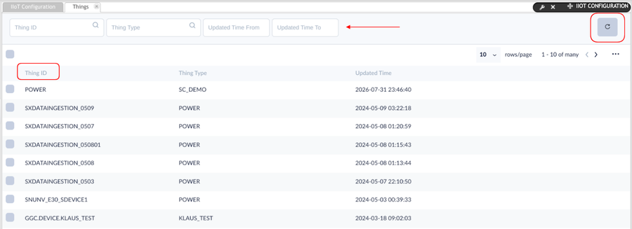
In this portlet, users can make sure whether the AWS Cloud has stored the data uploaded successfully or not.
To do so, follow the steps below:
- Navigate to: Shop Floor Control > Configuration > IIoT Configuration > Things.
Figure 28: Things Portlet
2. If the “Thing ID” is the same as the “id” configured in MqttTest.py file, it means that AWS Cloud has already stored the data uploaded.
3. To search for a specific thing, users can use the filters by Thing ID, Thing Time, and Thing Updated Time. Enter the appropriate value in the filter field; the system will automatically search the value.
4. Select the Refresh icon to refresh the records on the page.
Figure 29: Thing ID
Locations
The Locations portlet allows users to assign a location to the Edge Devices in order to identify their Physical Location.
To add a location, follow the steps below:
- Navigate to: Shop Floor Control > Configuration > IIoT Configuration > Locations.
Figure 30: Locations Portlet
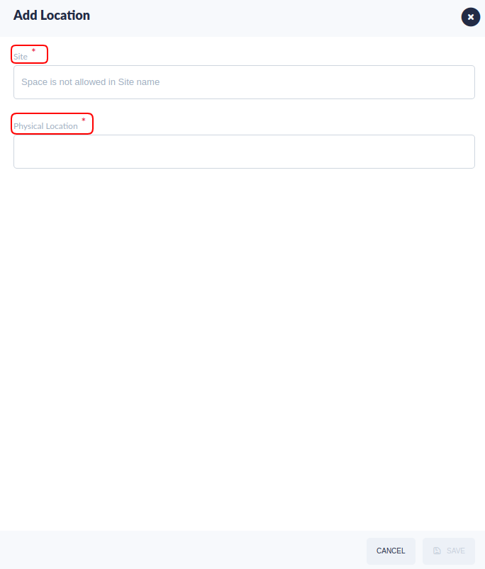
- Select the ADD LOCATIONS button.
Figure 31: ADD LOCATION Button
- Enter the Site.
- Enter the Physical Location.
- Select the SAVE button.
Figure 32: Creating A Location
Groups
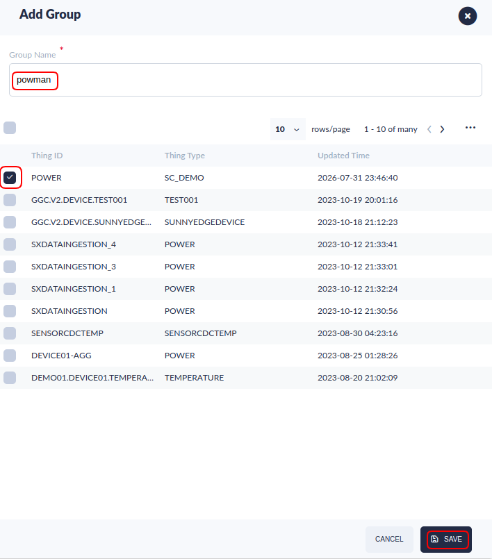
Users can create different groups of Edge Devices. Each group must have a unique name and one or more Thing IDs associated with it.
Add a Group
To add a group, follow the steps below:
- Navigate to: Shop Floor Control > Configuration > IIoT Configuration > Groups.
- Select the ADD GROUP button.
Figure 33: ADD GROUP Button
- Enter the Unique Group Name.
- Select a Thing ID.
- Select the SAVE button.
- Select the Refresh icon to refresh the records on the page.
Figure 34: Creating A Group
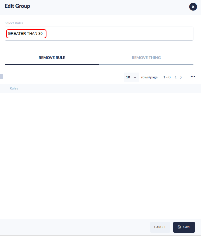
Add a Rule To An Existing Group
To add a rule, follow the steps below:
- Hover the mouse over a Group Name from the Group list.
- Select the Edit Group icon.
- Select a rule from the Select Rules drop-down list.
- Select the SAVE button.
Figure 35: Editing A Group
Notification Setup
Before creating any rules, users have to set up notifications. Each user can subscribe to one or more SNS topics (Simple Notification Service); these users will receive notifications via text messages or email.
To set up notifications, follow the steps below:
- Navigate to: Shop Floor Control > Configuration > IIoT Configuration > Notification Setup.
Figure 36: Notification Setup Portlet
DSS Notification Setup Portlet.png
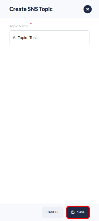
- Select the CREATE SNS TOPIC button. A pop-up window will appear.
Figure 37: CREATE SNS TOPIC Button
- Enter the Topic Name.
- Select the SAVE button.
- Select the Refresh icon to refresh the records on the page.
Figure 38: Create SNS Topic Pop-up Window
- Hover the cursor over the Topic.
- Select the Subscribe icon. A new pop-up window will appear.
Figure 39: Subscribe Icon
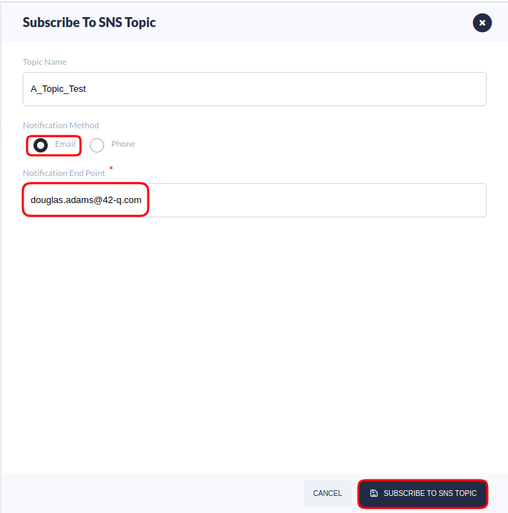
- Select the SUBSCRIBE TO SNS TOPIC button. A new pop-up window will appear.
Figure 40: SUBSCRIBE TO SNS TOPIC Button
DSS SUBSCRIBE TO SNS TOPIC Button.png
- Select the Notification Method (Email or Phone).
- Enter the Notification End Point (email address).
- Select the SUBSCRIBE TO SNS TOPIC button to save the information.
Figure 41: Subcribing To A SNS Topic
- The Subscribe List will display the Pending Confirmation and Confirmed End Points.
Figure 42: Subscribe List
- A confirmation mail will be sent to the entered email address. Open the mail.
- Select the Confirm subscription link.
- A window will be opened in a new tab confirming the subscription. To unsubscribe select the “click here to unsubscribe” link, else close the window.
Rules
In this portlet, users can create, view, edit, and delete rules. After setting up notifications, users may create rules that will trigger alerts. Each rule is associated with one or more Groups or Thing IDs.
- Navigate to: Shop Floor Control > Configuration > IIoT Configuration > Rules.
Figure 43: Rules Portlet
Add Rule
- Select the Add Rule button. A new pop-up window will appear.
Figure 44: Add rule
DSS addrule.png
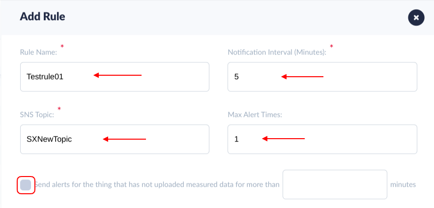
- Enter the Rule name, Notification interval, SNS topic, and Maximum Alert times.
- Check in the box to receive alerts for the things that have not uploaded measured data for more than the given time.
Figure 45: Entering Publish Rule Information
Next, select one of the two Bounds (rules):
- Threshold: This rule will trigger an alert whenever a measured value crosses a specific threshold.
- Independent: This rule will trigger an alert whenever a measured value satisfies the user-defined criteria.
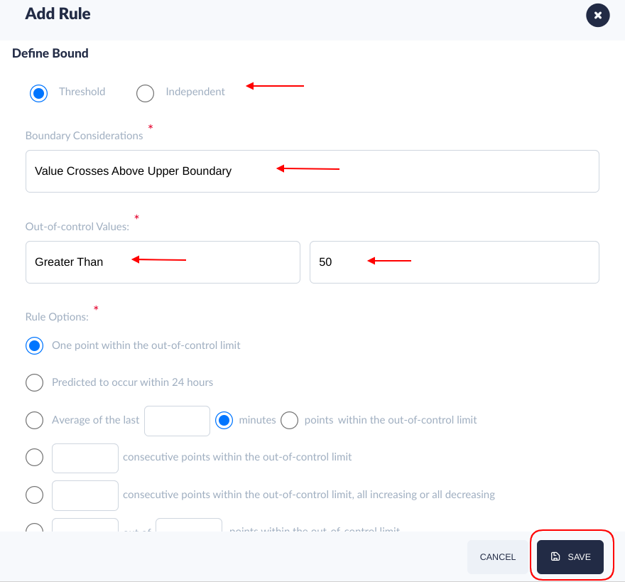
- If the Threshold is selected, choose one option from the Boundary Considerations list and the Control Values list.
- Enter the Limit Value.
- Select one of the Rule Options.
- Select the Save button.
Edit and Delete Rule
- Select the Edit button. A new pop-up window will appear.
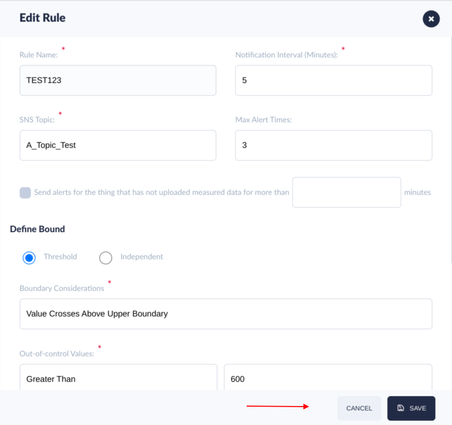
Figure 47: Edit Rule
- Users can edit Notification Interval, SNS topic, Maximum Alert times, andBoundary except Rule name.
Figure 48: Editing the options
- Select the Save button to complete the action.
- Select the Delete button to delete the rule.
Figure 49: Delete rule
Mapping
- Select the Mapping icon to apply a rule to the Things and Groups.
Figure 50: Mapping the rule
DSS mapping the rule.png
- Users can select Things and Groups for the rule or remove some existing things from the rule.
Figure 51: Selecting Things and Groups
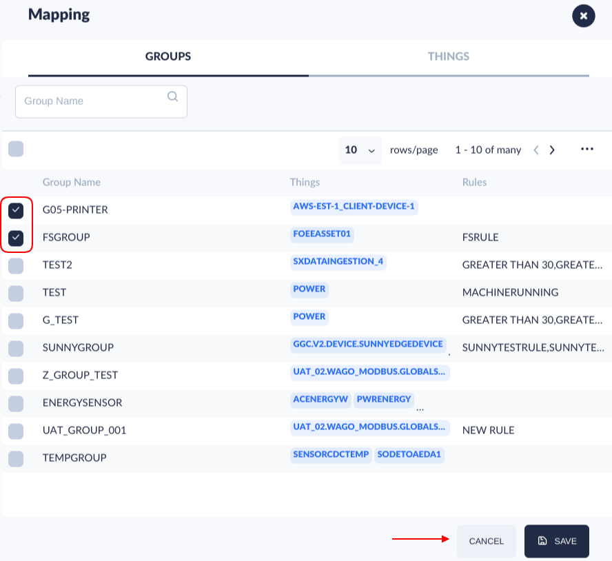
- Select the Save button to complete the action.
- Select the Refresh icon to refresh the records on the page.
Figure 52: Refresh the Page
DSS refreshpage.png
Alerts
After setting up notifications and rules, when a rule’s conditions comply, the alerts will be triggered, causing the notifications to be sent to the subscribed users.
To access the Alerts portlet, follow the steps below:
- Navigate to: Shop Floor Control > Configuration > IIoT Configuration > Alerts.
Figure 53: Alerts Portlet
- To search for a specific alert, users can use the filters: Thing ID, Rule, Rule Type, Status, and Alert Time. To do so, enter the appropriate value in the filter field; the system will automatically search the value.
- Select the Refresh icon to refresh the records on the page.
- Users can filter the Alerts record with multiple statuses
Figure 54: Thing ID And Rule Filters
Figure 55: Alert Status
- Alerting: Processing.
- Auto Stop Alert: There are ‘max alert times’ in the rule, if the system already sends out the message/mails equal to the ‘max alert times’, marking it as ‘Auto Stop Alert’.
- Acknowledged: If a user received the email or message, he could mark it as acknowledged to stop the system from sending events/emails. (User click the acknowledge button)
- Auto Processed: Edge device/Client application/OPC received events and response success.
- To acknowledge an alert, select an alert checkbox.
- Select the Acknowledge Alert button.
Figure 56: Acknowledge An Alert
Dashboard
- Navigate to: Reporting > IIoT Dashboard.
- Select the + icon to create a new widget.
- Enter the Widget Name.
- Select one of the types of widgets:
- Historical
- Predictive
- Variation: This option requires entering the Lower and Upper Control Limit.
- CPK/PPK(Single Thing Only): This option requires entering the Lower and Upper Control Limit. This type of widget is not possible to associate with groups, only Things.
- Select one or more Group Name from the GROUPS tab.
- Select the THINGS tab.
- Select the Thing ID that matches the "id" value previously configured in the MqttTest.py file.
- Select the SAVE button located at the end of the Add Widget Form.
Figure 58: Creating a Widget
- Select the show/hide icon to view the values of the widget created.
Figure 59: Show/Hide Icon
Note: Users can check the payload sent through either of the following:
- IIoT widget.

