Difference between revisions of "SOP-42Q-MES0078 Kit Verify Layout"
| (49 intermediate revisions by 5 users not shown) | |||
| Line 1: | Line 1: | ||
| − | <small>[[42Q_Cloud-Based_MES/MOMS|42Q Home]] > [[Shop_Floor_Control|Shop Floor Control]] > [[ | + | <small>[[42Q_Cloud-Based_MES/MOMS|42Q Home]] > [[Shop_Floor_Control|Shop Floor Control]] > [[Configuration]] > Kit Verify Layout</small><br/> |
| | ||
| Line 7: | Line 7: | ||
| | ||
| − | <center>'''Shop Floor | + | <center>'''Shop Floor Control'''</center> <center>''' Configuration '''</center> <center>'''Kit Verify Layout'''</center> <center>'''Version MES15.81'''</center> <center>'''Revision D1'''</center> <center> </center> <center> </center> |
| | ||
| − | |||
| − | |||
| − | + | == <span class="mw-headline" id="Introduction"><span class="mw-headline" id="Introduction"><span class="mw-headline" id="Introduction"><span class="mw-headline" id="Introduction"><span class="mw-headline" id="Introduction"><span class="mw-headline" id="Introduction"><span class="mw-headline" id="Introduction"><span class="mw-headline" id="Introduction"><span class="mw-headline" id="Introduction"><span class="mw-headline" id="Introduction"><span class="mw-headline" id="Introduction"><span class="mw-headline" id="Introduction"><span class="mw-headline" id="Introduction">Introduction</span></span></span></span></span></span></span></span></span></span></span></span></span> == | |
| − | |||
| − | == Introduction == | ||
| − | |||
| − | |||
| − | Kit Verify | + | '''Kit Verify '''is a tool that '''consolidates''' and '''validates''' all of the components in a Kit. A kit is provided to the Shop Floor by a warehouse in place of a shop order. Kit Verify allows users to verify that there are no missing components in a kit. |
| − | |||
| − | information. It also allows the user to add components to serial numbers attached to Shop Orders, replace components with defects, and modify changes in the database (Repair). | + | Kit Verify assists users in choosing the correct Shop Order that belongs to a certain Serial Number (product), separates Part Numbers that are serialized and that are not serialized (parts or components acquired by vendors), shows the quantity of the components that should be used, adds new Serial Numbers in the MES database, and prints Traveler Reports with the shop orders’ information. It also allows the user to add components to serial numbers attached to Shop Orders, replace components with defects, and modify changes in the database (Repair). |
| − | Kit Verify provides controlled communication integrated | + | Kit Verify provides controlled communication integrated into traceability software of products on the shop floor. This allows operational functionality rather than simply providing information configuration and registration. Kit Verify allows the moving of units (orders) of a station for others through commands made available by the application interface. |
| − | Kit Verify consists of the following modules in the MES portal: | + | Kit Verify consists of the following modules in the MES portal: |
| − | * | + | *'''Kit Verify Layout - '''responsible for the mapping of components by reference designators to layouts. |
| − | * | + | *'''Kit Verify -''' responsible for consolidation, integration, inspection, and repair of the kit. |
| | ||
| − | + | == <span class="mw-headline" id="Kit_Verify_and_Attributes_in_the_Generic_Attribute_Maintenance_module"><span class="mw-headline" id="Kit_Verify_and_Attributes_in_the_Generic_Attribute_Maintenance_module"><span class="mw-headline" id="Kit_Verify_and_Attributes_in_the_Generic_Attribute_Maintenance_module"><span class="mw-headline" id="Kit_Verify_and_Attributes_in_the_Generic_Attribute_Maintenance_module"><span class="mw-headline" id="Kit_Verify_and_Attributes_in_the_Generic_Attribute_Maintenance_module"><span class="mw-headline" id="Kit_Verify_and_Attributes_in_the_Generic_Attribute_Maintenance_module"><span class="mw-headline" id="Kit_Verify_and_Attributes_in_the_Generic_Attribute_Maintenance_module"><span class="mw-headline" id="Kit_Verify_and_Attributes_in_the_Generic_Attribute_Maintenance_module">Kit Verify and Attributes in the Generic Attribute Maintenance module</span></span></span></span></span></span></span></span> == | |
| − | + | The Generic Attribute Module provides configurable parameters that generate Kit Verify environments tailored to specific user requirements. A standard configuration is available for general use cases, while custom configurations can be implemented to address unique needs. | |
| − | + | See below the Attributes description and how it can be set to be used with Kit Verify. | |
| − | + | | |
| − | |||
| − | + | == <span class="mw-headline" id="Available_Kit_Verify_Attributes"><span class="mw-headline" id="Available_Kit_Verify_Attributes"><span class="mw-headline" id="Available_Kit_Verify_Attributes"><span class="mw-headline" id="Available_Kit_Verify_Attributes"><span class="mw-headline" id="Available_Kit_Verify_Attributes"><span class="mw-headline" id="Available_Kit_Verify_Attributes">Available Kit Verify Attributes</span></span></span></span></span></span> == | |
| − | < | ||
| − | ''' | + | #'''Kit_auto_save_enabled: '''This attribute was created to activate/deactivate the AutoSave counter in the Integration screen. The counter starts with 10 minutes and after this counter is = 0, the Kit Verify will save the process automatically. After the process is saved, the user will not be able to update the inserted register. This is valid just for the Integration AutoSave screen. |
| + | #'''Kit_complete:''' it forces the user to do the kit with all Top Level Assemblies at the same time. | ||
| + | #'''Kit_genband_enabled:''' Set if possible work in Kit Verify modules with GenBand project. | ||
| + | #'''Kit_genband_files_path: ''' It is the path of the folder where is stored the Genband files. | ||
| + | #'''Kit_inspection_defect_code:''' Users can customize the defect code that will be generated in the Inspection Station. | ||
| + | #'''Kit_inspection_symptom_code:''' Users can customize the symptom code that will be generated in the Inspection Station. | ||
| + | #'''Kit_nsnbcn_cust_enabled: ''' Set if is possible to work in Kit verify modules with NSN project. | ||
| + | #'''Kv_nsnbcn_unit_refdes:''' This generic attribute is used in the Kit Verify for NSN Customization | ||
| + | #'''Kit_repair_repair_code:''' Users can customize the repair code that will be generated in the Repair Station. | ||
| − | + | For more information please refer to the [https://42qrpt1.42-q.com/mes_wiki/index.php/SOP-MES0036_Generic_Attribute_Maintenance Generic Attribute] user manual. | |
| | ||
| − | + | == <span class="mw-headline" id="Kit_Verify_Layout_Configuration"><span class="mw-headline" id="Kit_Verify_Layout_Configuration"><span class="mw-headline" id="Kit_Verify_Layout_Configuration"><span class="mw-headline" id="Kit_Verify_Layout_Configuration"><span class="mw-headline" id="Kit_Verify_Layout_Configuration"><span class="mw-headline" id="Kit_Verify_Layout_Configuration"><span class="mw-headline" id="Kit_Verify_Layout_Configuration"><span class="mw-headline" id="Kit_Verify_Layout_Configuration"><span class="mw-headline" id="Kit_Verify_Layout_Configuration"><span class="mw-headline" id="Kit_Verify_Layout_Configuration"><span class="mw-headline" id="Kit_Verify_Layout_Configuration"><span class="mw-headline" id="Kit_Verify_Layout_Configuration"><span class="mw-headline" id="Kit_Verify_Layout_Configuration"><span class="mw-headline" id="Kit_Verify_Layout_Configuration"><span class="mw-headline" id="Kit_Verify_Layout_Configuration"><span class="mw-headline" id="Kit_Verify_Layout"><span class="mw-headline" id="Kit_Verify_Layout"><span class="mw-headline" id="Kit_Verify_Layout"><span class="mw-headline" id="Kit_Verify_Layout"><span class="mw-headline" id="Kit_Verify_Layout">Kit Verify Layout Configuration </span></span></span></span></span></span></span></span></span></span></span></span></span></span></span></span></span></span></span></span> == | |
| − | + | Kit Verify Layout facilitates the mapping of Shop Order components to assembly layouts using reference designators. | |
| − | | + | To access Kit Verify Layout, navigate to '''Shop Floor Control > Configuration > Kit Verify Layout''' |
| − | + | Users can manage assembly layouts by adding, editing, or copying them. The portlet presents all available Layout Configurations, organized by '''Part Number''', '''Project''', and '''Model'''. | |
| − | + | Users can refine the displayed layouts by applying filters based on Part Number, Project, Model, and/or Status (Active, Obsolete, or All). The layout list dynamically updates to reflect the user's filtering criteria. | |
| − | + | | |
| − | + | '''Figure 1: Kit Verify Layout''' | |
| − | |||
| − | + | [[File:KVL MainS.png|900px|KVL MainS.png]] | |
| | ||
| − | ''' | + | '''<u>Note:</u> '''To initiate a new search query, clear the existing field entries by selecting "Clear" and then input the desired search parameters. |
| − | + | | |
| | ||
| − | + | == <span class="mw-headline" id="Add_Layout_Configuration"><span class="mw-headline" id="Add_Layout_Configuration"><span class="mw-headline" id="Add_Layout_Configuration"><span class="mw-headline" id="Add_Layout_Configuration"><span class="mw-headline" id="Add_Layout_Configuration">Add Layout Configuration</span></span></span></span></span> == | |
| − | |||
| − | === Add | ||
Users can add a layout configuration to map reference designators to components on an assembly item. This simplifies the assembly process by providing visual elements for operators to follow. | Users can add a layout configuration to map reference designators to components on an assembly item. This simplifies the assembly process by providing visual elements for operators to follow. | ||
| − | + | To add a layout configuration, select the '''Add''' icon located above the Part Number list. | |
| | ||
| − | + | #Select the part number for a Shop Order that contains components with reference designators configured from the Part fuzzy search field | |
| − | |||
| − | |||
| | ||
| − | + | '''<u>Note:</u>''' The '''Project''' and '''Model''' fields are optional, but assist in the description of the layout configuration. | |
| | ||
| + | <ol start="2"> | ||
| + | <li>After selecting the part number, select the add icon from the tab below the Part field to '''upload an assembly layout.'''</li> | ||
| + | </ol> | ||
| + | <ol start="3"> | ||
| + | <li>A Confirm pop-up displays. Select '''Yes''' to open the '''File Upload''' screen.</li> | ||
| + | </ol> | ||
| − | '''Figure | + | <br/> '''Figure 2: Upload Assembly Layout''' |
| − | [[File: | + | [[File:SCP UploadAssemblyLayout.png|900px|SCP UploadAssemblyLayout.png]] |
| | ||
| − | + | 4. Select the assembly layout image file from the '''File Upload''' screen, and then select '''Open'''. | |
| | ||
| − | + | The image file is displayed in the first tab, and a subsequent tab is created to add multiple images if needed. | |
| | ||
| − | + | '''Figure 3: Assembly Layout''' | |
| − | |||
| − | |||
| − | + | [[File:SCP AssemblyLayout.png|900px|SCP AssemblyLayout.png]] | |
| − | + | 5. Select a reference designator from the drop-down box provided. | |
| − | + | 6. Select a mapping type from the options provided: '''Square''', '''Circle''', '''Freeform.''' | |
| − | + | 7. Map the reference designator to the appropriate component on the Assembly Layout. | |
| − | + | 8. Select the green checkmark at the top right of the image to save the mapping. | |
| − | |||
| − | |||
| | ||
| − | '''Figure | + | '''Figure 4: Assembly Layout Mapping''' |
| − | [[File: | + | [[File:SCP AssemblyLayoutMapping.png|900px|SCP AssemblyLayoutMapping.png]] |
| | ||
| − | + | Users can add multiple mappings by selecting additional reference designators from the'''Reference Designator '''drop-down box. | |
| − | |||
| − | |||
| − | |||
| − | |||
| − | |||
| − | |||
| | ||
| − | '''Figure | + | '''Figure 5: Multiple Mappings Example''' |
| − | [[File: | + | [[File:SCP MultipleMappingsExample.png|900px|SCP MultipleMappingsExample.png]] |
| | ||
| − | + | Once all mappings are created, select '''Save'''. | |
| − | + | To return to the'''Kit Verify Layout''' main page, select '''Close'''. The new Layout Configuration will be added to the list. | |
| − | |||
| − | ''' | ||
| − | |||
| − | |||
| | ||
| − | + | == <span class="mw-headline" id="Edit_Layout_Configuration"><span class="mw-headline" id="Edit_Layout_Configuration"><span class="mw-headline" id="Edit_Layout_Configuration"><span class="mw-headline" id="Edit_Layout_Configuration"><span class="mw-headline" id="Edit_Layout_Configuration"><span class="mw-headline" id="Edit_Layout_Configuration"><span class="mw-headline" id="Edit_Layout_Configuration"><span class="mw-headline" id="Edit_Layout_Configuration"><span class="mw-headline" id="Edit_Layout_Configuration"><span class="mw-headline" id="Edit_Layout_Configuration"><span class="mw-headline" id="Edit_Layout_Configuration"><span class="mw-headline" id="Edit_Layout_Configuration"><span class="mw-headline" id="Edit_Layout_Configuration"><span class="mw-headline" id="Edit_Layout_Configuration"><span class="mw-headline" id="Edit"><span class="mw-headline" id="Edit"><span class="mw-headline" id="Edit"><span class="mw-headline" id="Edit"><span class="mw-headline" id="Edit"><span class="mw-headline" id="Edit"><span class="mw-headline" id="Edit"><span class="mw-headline" id="Edit">Edit </span></span></span></span></span></span></span></span><span class="mw-headline"><span class="mw-headline"><span class="mw-headline"><span class="mw-headline"><span class="mw-headline"><span class="mw-headline"><span class="mw-headline"><span class="mw-headline">Layout Configuration</span></span></span></span></span></span></span></span></span></span></span></span></span></span></span></span></span></span></span></span></span></span> == | |
| − | + | Users can edit any available layout configuration. While editing, users can add or remove Layout Assemblies and their mappings. | |
| | ||
| − | |||
| − | |||
| − | |||
| − | |||
1. To edit a Layout Configuration, select the layout configuration and then select '''Edit''' from the '''KV Configuration '''main page. | 1. To edit a Layout Configuration, select the layout configuration and then select '''Edit''' from the '''KV Configuration '''main page. | ||
| Line 173: | Line 155: | ||
| | ||
| − | '''Figure | + | '''Figure 6: Edit Layout Configuration''' |
| − | [[File: | + | [[File:SCP EditLayoutConfiguration.png|900px|SCP EditLayoutConfiguration.png]] |
| | ||
| Line 191: | Line 173: | ||
| | ||
| − | '''Figure | + | '''Figure 7: Remove Mapping''' |
| − | [[File: | + | [[File:SCP RemoveMapping.png|900px|SCP RemoveMapping.png]] |
| | ||
| − | === Copy === | + | == <span class="mw-headline" id="Copy_Layout_Configuration"><span class="mw-headline" id="Copy_Layout_Configuration"><span class="mw-headline" id="Copy_Layout_Configuration"><span class="mw-headline" id="Copy_Layout_Configuration"><span class="mw-headline" id="Copy_Layout_Configuration"><span class="mw-headline" id="Copy_Layout_Configuration"><span class="mw-headline" id="Copy_Layout_Configuration"><span class="mw-headline" id="Copy_Layout_Configuration"><span class="mw-headline" id="Copy_Layout_Configuration"><span class="mw-headline" id="Copy_Layout_Configuration"><span class="mw-headline" id="Copy_Layout_Configuration"><span class="mw-headline" id="Copy_Layout_Configuration"><span class="mw-headline" id="Copy_Layout_Configuration"><span class="mw-headline" id="Copy_Layout_Configuration"><span class="mw-headline" id="Copy_Layout_Configuration"><span class="mw-headline" id="Copy"><span class="mw-headline" id="Copy"><span class="mw-headline" id="Copy"><span class="mw-headline" id="Copy"><span class="mw-headline" id="Copy"><span class="mw-headline" id="Copy"><span class="mw-headline" id="Copy"><span class="mw-headline" id="Copy">Copy </span></span></span></span></span></span></span></span><span class="mw-headline"><span class="mw-headline"><span class="mw-headline"><span class="mw-headline"><span class="mw-headline"><span class="mw-headline"><span class="mw-headline"><span class="mw-headline">Layout Configuration</span></span></span></span></span></span></span></span></span></span></span></span></span></span></span></span></span></span></span></span></span></span></span> == |
Users can copy Layout Configurations by adding a new Part Number, Project, and/or Model to an existing configuration. | Users can copy Layout Configurations by adding a new Part Number, Project, and/or Model to an existing configuration. | ||
| Line 207: | Line 189: | ||
| | ||
| − | '''Figure | + | '''Figure 8: Copy Layout Configuration''' |
| − | [[File: | + | [[File:SCP CopyLayoutConfiguration.png|900px|SCP CopyLayoutConfiguration.png]] |
| | ||
| Line 216: | Line 198: | ||
4. The Layout Configuration will display and the user can make any necessary changes. | 4. The Layout Configuration will display and the user can make any necessary changes. | ||
| − | |||
| − | |||
| − | |||
| − | |||
| − | |||
| − | |||
| − | |||
| − | |||
| − | |||
| − | |||
| − | |||
| − | |||
| − | |||
| − | |||
| − | |||
| − | |||
| − | |||
| − | |||
| − | |||
| − | |||
| − | |||
| − | |||
| − | |||
| − | |||
| − | |||
| − | |||
| − | |||
| − | |||
| − | |||
| − | |||
| − | |||
| − | |||
| − | |||
| − | |||
| − | |||
| − | |||
| − | |||
| − | |||
| − | |||
| − | |||
| − | |||
| − | |||
| − | |||
| − | |||
| − | |||
| − | |||
| − | |||
| − | |||
| − | |||
| − | |||
| − | |||
| − | |||
| − | |||
| − | |||
| − | |||
| − | |||
| − | |||
| − | |||
| − | |||
| − | |||
| − | |||
| − | |||
| − | |||
| − | |||
| − | |||
| − | |||
| − | |||
| − | |||
| − | |||
| − | |||
| − | |||
| − | |||
| − | |||
| − | |||
| − | |||
| − | |||
| − | |||
| − | |||
| − | |||
| − | |||
| − | |||
| − | |||
| − | |||
| − | |||
| − | |||
| − | |||
| − | |||
| − | |||
| − | |||
| − | |||
| − | |||
| − | |||
| − | |||
| − | |||
| − | |||
| − | |||
| − | |||
| − | |||
| − | |||
| − | |||
| − | |||
| − | |||
| − | |||
| − | |||
| − | |||
| − | |||
| − | |||
| − | |||
| − | |||
| − | |||
| − | |||
| − | |||
| − | |||
| − | |||
| − | |||
| − | |||
| − | |||
| − | |||
| − | |||
| − | |||
| − | |||
| − | |||
| − | |||
| − | |||
| − | |||
| − | |||
| − | |||
| − | |||
| − | |||
| − | |||
| − | |||
| − | |||
| − | |||
| − | |||
| − | |||
| − | |||
| − | |||
| − | |||
| − | |||
| − | |||
| − | |||
| − | |||
| − | |||
| − | |||
| − | |||
| − | |||
| − | |||
| − | |||
| − | |||
| − | |||
| − | |||
| − | |||
| − | |||
| − | |||
| − | |||
| − | |||
| − | |||
| − | |||
| − | |||
| − | |||
| − | |||
| − | |||
| − | |||
| − | |||
| − | |||
| − | |||
| − | |||
| − | |||
| − | |||
| − | |||
| − | |||
| − | |||
| − | |||
| − | |||
| − | |||
| − | |||
| − | |||
| − | |||
| − | |||
| − | |||
| − | |||
| − | |||
| − | |||
| − | |||
| − | |||
| − | |||
| − | |||
| − | |||
| − | |||
| − | |||
| − | |||
| − | |||
| − | |||
| − | |||
| − | |||
| − | |||
| − | |||
| − | |||
| − | |||
| − | |||
| − | |||
| − | |||
| − | |||
| − | |||
| − | |||
| − | |||
| − | |||
| − | |||
| − | |||
| − | |||
| − | |||
| − | |||
| − | |||
| − | |||
| − | |||
| − | |||
| − | |||
| − | |||
| − | |||
| − | |||
| − | |||
| − | |||
| − | |||
| − | |||
| − | |||
| − | |||
| − | |||
| − | |||
| − | |||
| − | |||
| − | |||
| − | |||
| − | |||
| − | |||
| − | |||
| − | |||
| − | |||
| − | |||
| − | |||
| − | |||
| − | |||
| − | |||
| − | |||
| − | |||
| − | |||
| − | |||
| − | |||
| − | |||
| − | |||
| − | |||
| − | |||
| − | |||
| − | |||
| − | |||
| − | |||
| − | |||
| − | |||
| − | |||
| − | |||
| − | |||
| − | |||
| − | |||
| − | |||
| − | |||
| − | |||
| − | |||
| − | |||
| − | |||
| − | |||
| − | |||
| − | |||
| − | |||
| − | |||
| − | |||
| − | |||
| − | |||
| − | |||
| − | |||
| − | |||
| − | |||
| − | |||
| − | |||
| − | |||
| − | |||
| − | |||
| − | |||
| − | |||
| − | |||
| − | |||
| − | |||
| − | |||
| − | |||
| − | |||
| − | |||
| − | |||
| − | |||
| − | |||
| − | |||
| − | |||
| − | |||
| − | |||
| − | |||
| − | |||
| − | |||
| − | |||
| − | |||
| − | |||
| − | |||
| − | |||
| − | |||
| − | |||
| − | |||
| − | |||
| − | |||
| − | |||
| − | |||
| − | |||
| − | |||
| − | |||
| − | |||
| − | |||
| − | |||
| − | |||
| − | |||
| − | |||
| − | |||
| − | |||
| − | |||
| − | |||
| − | |||
| − | |||
| − | |||
| − | |||
| − | |||
| − | |||
| − | |||
| − | |||
| − | |||
| − | |||
| − | |||
| − | |||
| − | |||
| − | |||
| − | |||
| − | |||
| − | |||
| − | |||
| − | |||
| − | |||
| − | |||
| − | |||
| − | |||
| − | |||
| − | |||
| − | |||
| − | |||
| − | |||
| − | |||
| − | |||
| − | |||
| − | |||
| − | |||
| − | |||
| | ||
| − | + | == <span class="mw-headline" id="Obsolete"><span class="mw-headline" id="Obsolete"><span class="mw-headline" id="Obsolete"><span class="mw-headline" id="Obsolete"><span class="mw-headline" id="Obsolete"><span class="mw-headline" id="Obsolete"><span class="mw-headline" id="Obsolete"><span class="mw-headline" id="Obsolete"><span class="mw-headline" id="Obsolete"><span class="mw-headline" id="Obsolete"><span class="mw-headline" id="Obsolete"><span class="mw-headline" id="Obsolete"><span class="mw-headline" id="Obsolete"><span class="mw-headline" id="Obsolete"><span class="mw-headline" id="Obsolete"><span class="mw-headline" id="Obsolete"><span class="mw-headline" id="Obsolete"><span class="mw-headline" id="Obsolete"><span class="mw-headline" id="Obsolete"><span class="mw-headline" id="Obsolete"><span class="mw-headline" id="Obsolete"><span class="mw-headline" id="Obsolete"><span class="mw-headline" id="Obsolete">Obsolete</span></span></span></span></span></span></span></span></span></span></span></span></span></span></span></span></span></span></span></span></span></span></span> == | |
| − | + | Multiple layouts can exist for a single part number with a unique project and model. When the Kit enters the Integration step in Kit Verify, all layouts for the part number will be listed. The user can only choose one layout per kit. To limit the number of layouts that are available for a given part number, the obsolete function can be used. | |
| − | + | To obsolete a layout, select the '''Obsolete '''radio button at the top left of the Layout Configuration screen. Select '''Save '''to obsolete the layout. | |
| | ||
| − | + | '''Figure 9: Obsolete''' | |
| − | + | [[File:SCP Obsolete.png|900px|SCP Obsolete.png]] | |
| − | |||
| − | |||
| | ||
| − | + | <u>'''Note:'''</u> If the layout is already attached to a kit in '''Kit Verify''', it will still be available for use. The obsolete function only removes the layout from the list of available layouts for new kits entering the Integration step. | |
| − | |||
| − | |||
| − | |||
| − | |||
| − | |||
| − | |||
| − | |||
| − | |||
| | ||
| − | + | == <span class="mw-headline" id="Export_Layout_Configuration"><span class="mw-headline" id="Export_Layout_Configuration"><span class="mw-headline" id="Export_Layout_Configuration"><span class="mw-headline" id="Export_Layout_Configuration"><span class="mw-headline" id="Export_Layout_Configuration"><span class="mw-headline" id="Export_Layout_Configuration"><span class="mw-headline" id="Export_Layout_Configuration"><span class="mw-headline" id="Export_Layout_Configuration"><span class="mw-headline" id="Export_Layout_Configuration"><span class="mw-headline" id="Export_Layout_Configuration"><span class="mw-headline" id="Export_Layout_Configuration"><span class="mw-headline" id="Export_Layout_Configuration"><span class="mw-headline" id="Export_Layout_Configuration"><span class="mw-headline" id="Export_Layout_Configuration">Export Layout Configuration</span></span></span></span></span></span></span></span></span></span></span></span></span></span> == | |
| − | + | The user is able to EXPORT the Part Number List as it is displayed on the page in several formats (.CSV, .HTML, PDF, .XLS). | |
| − | + | To export the Layout list: | |
| − | |||
| − | |||
| − | + | '''Figure 10: Export Layout Configuration''' | |
| − | [[File: | + | [[File:SCP ExportLayoutConfiguration.png|900px|SCP ExportLayoutConfiguration.png]] |
| − | |||
| − | |||
| − | |||
| − | |||
| − | |||
| | ||
| − | + | Select the file type (.CSV, HTML, PDF, XLS), the page orientation (portrait or landscape), and the fields to be displayed in the file to be exported by double-clicking on the field or selecting the green arrows. Click on Export to save the file.<br/> | |
| − | |||
| − | |||
| − | |||
| − | |||
| − | |||
| − | |||
| | ||
| − | + | ---- | |
| | ||
| − | |||
| − | |||
| − | |||
| − | |||
| − | |||
| − | |||
| − | |||
| − | |||
| − | |||
| − | |||
| − | |||
| − | |||
| − | |||
| − | |||
| − | |||
| − | |||
| − | |||
| − | |||
| − | |||
| − | |||
| − | |||
| − | |||
| − | |||
| − | |||
| − | |||
| − | |||
| − | |||
| − | |||
| − | |||
| − | |||
| − | |||
| − | |||
| − | |||
| − | |||
| − | |||
| − | |||
| − | |||
| − | |||
| − | |||
| − | |||
| − | |||
| − | |||
| − | |||
| − | |||
| − | |||
| − | |||
| − | |||
| − | |||
| − | |||
| − | |||
| − | |||
| − | |||
| − | |||
| − | |||
| − | |||
| − | |||
| − | |||
| − | |||
| − | |||
| − | |||
| − | |||
| − | |||
| − | |||
| − | |||
| − | |||
| − | |||
| − | |||
| − | |||
| − | |||
| − | |||
| − | |||
| − | |||
| − | |||
| − | |||
| − | |||
| − | |||
| − | |||
| − | |||
| − | |||
| − | |||
| − | |||
| − | |||
| − | |||
| − | |||
| − | |||
| − | |||
| − | |||
| − | |||
| − | |||
| − | |||
| − | |||
| − | |||
| − | |||
| − | |||
| − | |||
| − | |||
| − | |||
| − | |||
| − | |||
| − | |||
| − | |||
| − | |||
| − | |||
| − | |||
| − | |||
| − | |||
| − | |||
| − | |||
| − | |||
| − | |||
| − | |||
| − | |||
| − | |||
| − | |||
| − | |||
| − | |||
| − | |||
| − | |||
| − | |||
| − | |||
| − | |||
| − | |||
| − | |||
| − | |||
| − | |||
| − | |||
| − | |||
| − | |||
| − | |||
| − | |||
| − | |||
| − | |||
| − | |||
| − | |||
| − | |||
| − | |||
| − | |||
| − | |||
| − | |||
| − | |||
Latest revision as of 22:05, 26 September 2024
42Q Home > Shop Floor Control > Configuration > Kit Verify Layout
Contents
Introduction
Kit Verify is a tool that consolidates and validates all of the components in a Kit. A kit is provided to the Shop Floor by a warehouse in place of a shop order. Kit Verify allows users to verify that there are no missing components in a kit.
Kit Verify assists users in choosing the correct Shop Order that belongs to a certain Serial Number (product), separates Part Numbers that are serialized and that are not serialized (parts or components acquired by vendors), shows the quantity of the components that should be used, adds new Serial Numbers in the MES database, and prints Traveler Reports with the shop orders’ information. It also allows the user to add components to serial numbers attached to Shop Orders, replace components with defects, and modify changes in the database (Repair).
Kit Verify provides controlled communication integrated into traceability software of products on the shop floor. This allows operational functionality rather than simply providing information configuration and registration. Kit Verify allows the moving of units (orders) of a station for others through commands made available by the application interface.
Kit Verify consists of the following modules in the MES portal:
- Kit Verify Layout - responsible for the mapping of components by reference designators to layouts.
- Kit Verify - responsible for consolidation, integration, inspection, and repair of the kit.
Kit Verify and Attributes in the Generic Attribute Maintenance module
The Generic Attribute Module provides configurable parameters that generate Kit Verify environments tailored to specific user requirements. A standard configuration is available for general use cases, while custom configurations can be implemented to address unique needs.
See below the Attributes description and how it can be set to be used with Kit Verify.
Available Kit Verify Attributes
- Kit_auto_save_enabled: This attribute was created to activate/deactivate the AutoSave counter in the Integration screen. The counter starts with 10 minutes and after this counter is = 0, the Kit Verify will save the process automatically. After the process is saved, the user will not be able to update the inserted register. This is valid just for the Integration AutoSave screen.
- Kit_complete: it forces the user to do the kit with all Top Level Assemblies at the same time.
- Kit_genband_enabled: Set if possible work in Kit Verify modules with GenBand project.
- Kit_genband_files_path: It is the path of the folder where is stored the Genband files.
- Kit_inspection_defect_code: Users can customize the defect code that will be generated in the Inspection Station.
- Kit_inspection_symptom_code: Users can customize the symptom code that will be generated in the Inspection Station.
- Kit_nsnbcn_cust_enabled: Set if is possible to work in Kit verify modules with NSN project.
- Kv_nsnbcn_unit_refdes: This generic attribute is used in the Kit Verify for NSN Customization
- Kit_repair_repair_code: Users can customize the repair code that will be generated in the Repair Station.
For more information please refer to the Generic Attribute user manual.
Kit Verify Layout Configuration
Kit Verify Layout facilitates the mapping of Shop Order components to assembly layouts using reference designators.
To access Kit Verify Layout, navigate to Shop Floor Control > Configuration > Kit Verify Layout
Users can manage assembly layouts by adding, editing, or copying them. The portlet presents all available Layout Configurations, organized by Part Number, Project, and Model.
Users can refine the displayed layouts by applying filters based on Part Number, Project, Model, and/or Status (Active, Obsolete, or All). The layout list dynamically updates to reflect the user's filtering criteria.
Figure 1: Kit Verify Layout
Note: To initiate a new search query, clear the existing field entries by selecting "Clear" and then input the desired search parameters.
Add Layout Configuration
Users can add a layout configuration to map reference designators to components on an assembly item. This simplifies the assembly process by providing visual elements for operators to follow.
To add a layout configuration, select the Add icon located above the Part Number list.
- Select the part number for a Shop Order that contains components with reference designators configured from the Part fuzzy search field
Note: The Project and Model fields are optional, but assist in the description of the layout configuration.
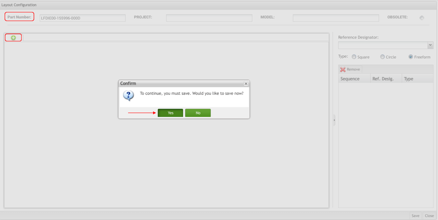
- After selecting the part number, select the add icon from the tab below the Part field to upload an assembly layout.
- A Confirm pop-up displays. Select Yes to open the File Upload screen.
Figure 2: Upload Assembly Layout
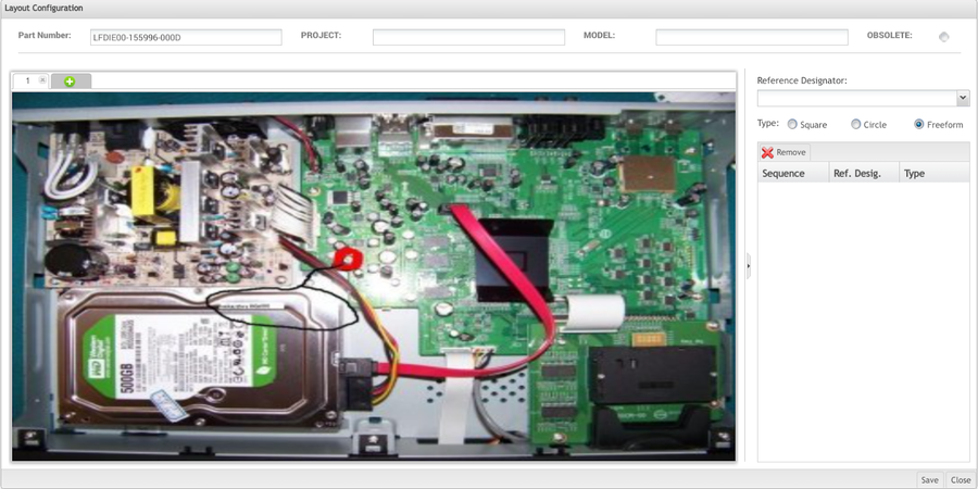
4. Select the assembly layout image file from the File Upload screen, and then select Open.
The image file is displayed in the first tab, and a subsequent tab is created to add multiple images if needed.
Figure 3: Assembly Layout
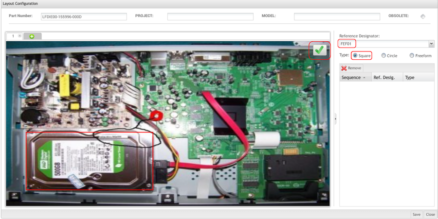
5. Select a reference designator from the drop-down box provided.
6. Select a mapping type from the options provided: Square, Circle, Freeform.
7. Map the reference designator to the appropriate component on the Assembly Layout.
8. Select the green checkmark at the top right of the image to save the mapping.
Figure 4: Assembly Layout Mapping
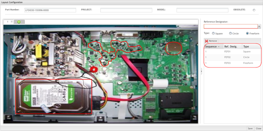
Users can add multiple mappings by selecting additional reference designators from theReference Designator drop-down box.
Figure 5: Multiple Mappings Example
Once all mappings are created, select Save.
To return to theKit Verify Layout main page, select Close. The new Layout Configuration will be added to the list.
Edit Layout Configuration
Users can edit any available layout configuration. While editing, users can add or remove Layout Assemblies and their mappings.
1. To edit a Layout Configuration, select the layout configuration and then select Edit from the KV Configuration main page.
Figure 6: Edit Layout Configuration
2. The Layout Configuration portlet displays. The user can add or remove assembly layouts and mappings from this portlet.
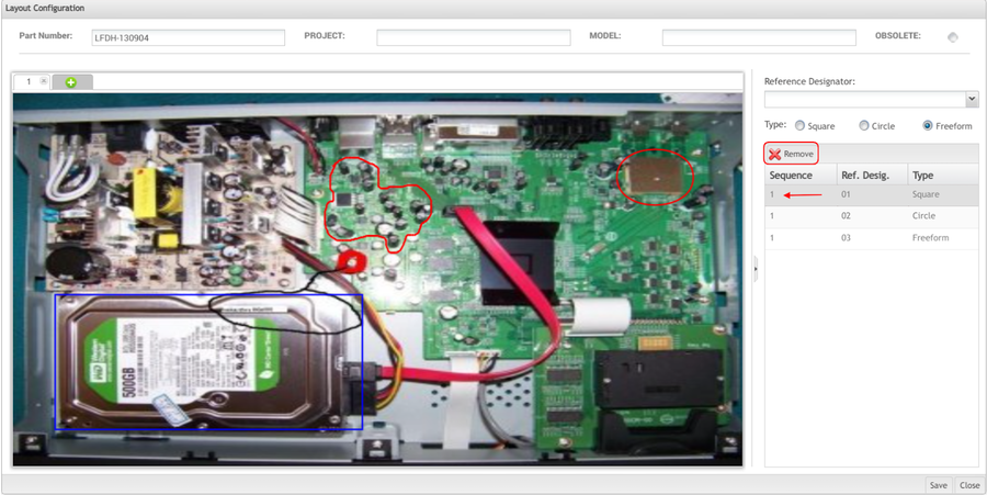
3. To remove an assembly layout, select the "x" in the top right of the image tab.
4. To remove a mapping, select the mapping from the list and then select Remove.
5. Select Save to confirm the changes.
6. Select Close to return to the KV Configuration main screen.
Figure 7: Remove Mapping
Copy Layout Configuration
Users can copy Layout Configurations by adding a new Part Number, Project, and/or Model to an existing configuration.
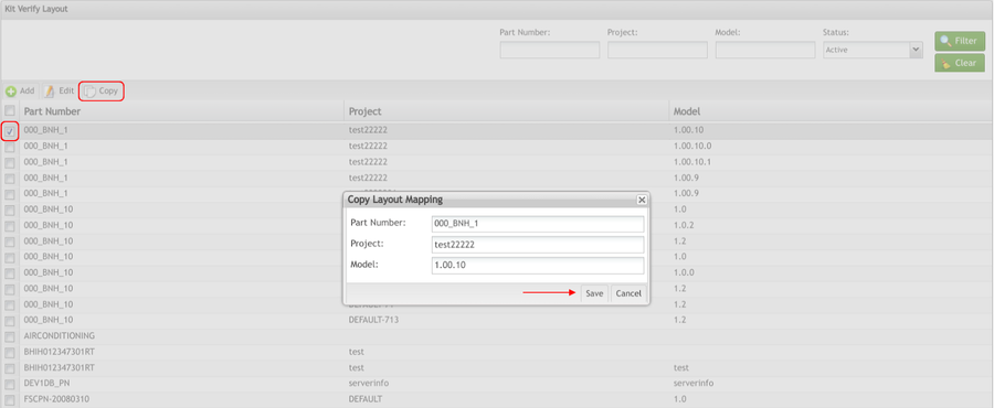
1. To copy a Layout Configuration, select the configuration from the list and then select Copy.
2. The Copy Layout Mapping form displays:
Figure 8: Copy Layout Configuration
3. Either change the Part Number or change/add the Project and Model, and then select Save.
4. The Layout Configuration will display and the user can make any necessary changes.
Obsolete
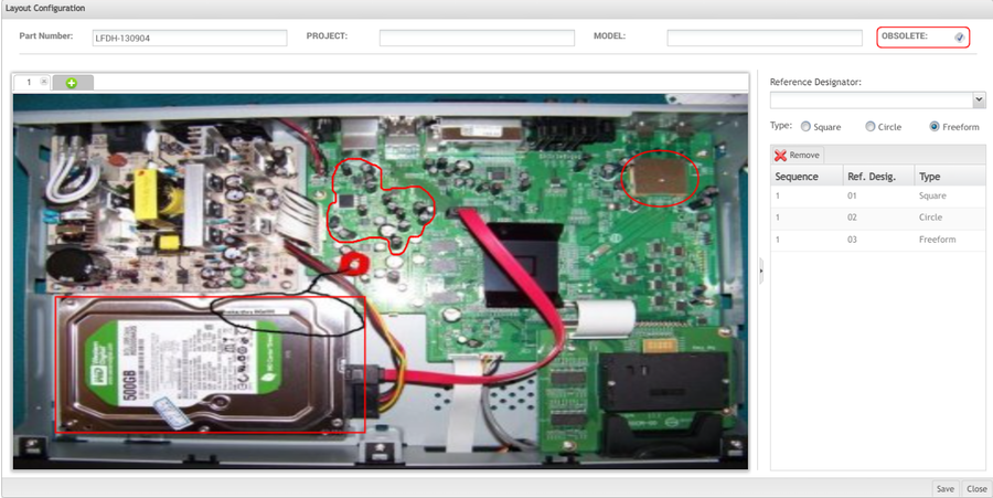
Multiple layouts can exist for a single part number with a unique project and model. When the Kit enters the Integration step in Kit Verify, all layouts for the part number will be listed. The user can only choose one layout per kit. To limit the number of layouts that are available for a given part number, the obsolete function can be used.
To obsolete a layout, select the Obsolete radio button at the top left of the Layout Configuration screen. Select Save to obsolete the layout.
Figure 9: Obsolete
Note: If the layout is already attached to a kit in Kit Verify, it will still be available for use. The obsolete function only removes the layout from the list of available layouts for new kits entering the Integration step.
Export Layout Configuration
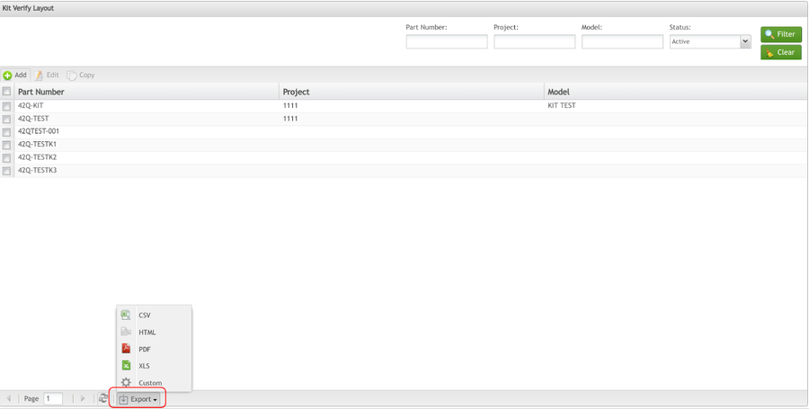
The user is able to EXPORT the Part Number List as it is displayed on the page in several formats (.CSV, .HTML, PDF, .XLS).
To export the Layout list:
Figure 10: Export Layout Configuration
Select the file type (.CSV, HTML, PDF, XLS), the page orientation (portrait or landscape), and the fields to be displayed in the file to be exported by double-clicking on the field or selecting the green arrows. Click on Export to save the file.

