Difference between revisions of "Configuration"
Dane parker (talk | contribs) |
Dane parker (talk | contribs) |
||
| Line 525: | Line 525: | ||
=== Alert Distribution === | === Alert Distribution === | ||
| + | To access the Alert Distribution functionality, from Tasks panel, click on '''Alert Distribution'''. | ||
| + | |||
| + | |||
| + | '''Figure 53: Shop Order List''' | ||
| + | |||
| + | [[File:KV53.png]] | ||
| + | |||
| + | |||
| + | The alert distribution list should be like a profile. We can select the user for each program and these users will receive an email alert base on xml template. | ||
| + | |||
| + | |||
| + | The Alert Distribution list displays: | ||
| + | |||
| + | |||
| + | '''Figure 54: Alert Distribution''' | ||
| + | |||
| + | [[File:KV54.png|800px]] | ||
| + | |||
| + | |||
| + | From this screen, the user is able to add, edit, copy or delete alerts distribution. See the next topics for more information. | ||
| + | |||
| + | |||
| + | === Adding Alert Distribution === | ||
| + | '''Figure 55: Adding Alert Distribution''' | ||
| + | |||
| + | [[File:KV55.png|800px]] | ||
| + | |||
| + | The Add Alert Distribution window displays: | ||
| + | |||
| + | |||
| + | '''Figure 56: Add Alert Distribution''' | ||
| + | |||
| + | [[File:KV56.png]] | ||
| + | |||
| + | |||
| + | To add an Alert Distribution, follow the steps bellow: | ||
| + | |||
| + | # In Task Panel click in "'''Add Alert Distribution"''' option; | ||
| + | # Fill the mandatory fields (Distribution Name and Receivers); | ||
| + | # Click in "'''Ok'''" button; | ||
| + | # Confirm the Alert Distribution creation. | ||
| + | |||
| + | The "Alert Distribution" window closes and the "Alert" is displayed with the recorded "Alert" in the table. | ||
| + | |||
| + | The user can search for receivers. Click on “+” to add or “-” to delete. | ||
| + | |||
| + | |||
| + | === Editing Alert Distribution === | ||
| + | '''Figure 57: Editing Alert Distribution.''' | ||
| + | |||
| + | [[File:KV57.png|800px]] | ||
| + | |||
| + | |||
| + | Follow the steps bellow to edit an alert distribution: | ||
| + | |||
| + | |||
| + | # On the Alert Distribution list, select an existing Alert; | ||
| + | # Click the Edit icon; The Alert Distribution screen displays. It is the same for Add Distribution alert. | ||
| + | # Change the mandatory fields; | ||
| + | # Click "'''OK'''" button | ||
| + | # Confirm the Edit. | ||
| + | |||
| + | === Copying Alert Distribution === | ||
| + | '''Figure 58: Copying Alert Distribution''' | ||
| + | |||
| + | [[File:KV58.png|800px]] | ||
| + | |||
| + | |||
| + | The copy feature allows the user to copy alert information. Follow the steps bellow: | ||
| + | |||
| + | |||
| + | # On the Alert Distribution List, select an existing Alert; | ||
| + | # Click the Copy Icon; | ||
| + | # Change the mandatory fields; | ||
| + | # Click "'''OK'''" button. | ||
| + | |||
| + | === Deleting Alert Distribution === | ||
| + | '''Figure 59: Deleting Alert Distribution''' | ||
| + | |||
| + | [[File:KV59.png|800px]] | ||
| + | |||
| + | |||
| + | Follow the steps bellow to delete an Alert: | ||
| + | |||
| + | |||
| + | # On the Alert Distribution List, select an existing Alert; | ||
| + | # Click the Delete icon; | ||
| + | # Click "'''OK'''" button. | ||
| + | # A confirmation box displays. | ||
| + | # The Alert is deleted. | ||
== Multi-Level Contrainer Configuration == | == Multi-Level Contrainer Configuration == | ||
Revision as of 18:22, 20 January 2014
Contents
- 1 SFDC Configuration
- 2 Kit Verify Configuration
- 2.1 Layout Configuration
- 2.2 Test Configuration
- 2.3 Performing Searches
- 2.4 Adding/Editing Test Configuration;
- 2.5 Part Process Control;
- 2.6 Group Test Configuration;
- 2.7 Integration
- 2.8 Finding Top Assemblies to Integrate
- 2.9 Showing Integration Information
- 2.10 Alert Distribution
- 2.11 Adding Alert Distribution
- 2.12 Editing Alert Distribution
- 2.13 Copying Alert Distribution
- 2.14 Deleting Alert Distribution
- 3 Multi-Level Contrainer Configuration
- 4 Employee Validation
- 5 SQC Configuration
- 6 Labor Tracking Maintenance
- 7 Algorithm Tool
- 8 MDS Labels
SFDC Configuration
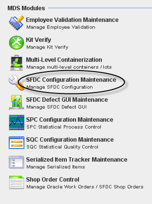
1. To access the SFDC Configuration module, click on SFDC Configuration in the main MDS Modules window.
Figure 1: MDS Client Modules – SFDC Configuration Maintenance
GENERAL NOTES: a)A user only has access to the modules assigned to his/her profile. Profile permissions are granted in the MDS PRAC (Program Access Control) Module by the Program Admin user.
b)Any/all reports printed from jMDS modules will print to the default printer for the workstation.
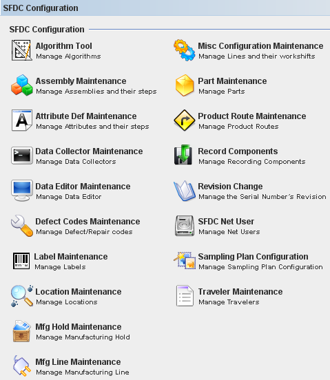
2. The SFDC Configuration main window is displayed.
Figure 2: SFDC Configuration Modules
This is the main SFDC Configuration Module window.
Kit Verify Configuration
The Kit Verify consolidates or validates all of component that we have in a “Kit” that warehouse give to the floor versus the shop order, in order to know if we have missing component in the Kit.
This module is integrated to MDS Client Application and will be available to all Sanmina's Plants.
Layout Configuration
The function of this interface is to allow the user to Add, Copy or Edit an assembly layout in the Kit Verify MDS Database.
Note 1: If Oracle does not send the reference Designator information to MDS the system will allow entering it manually.
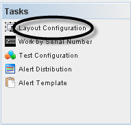
To access the Layout functionality, click on Layout Configuration at Tasks panel.
Figure 4: Choose Layout Configuration
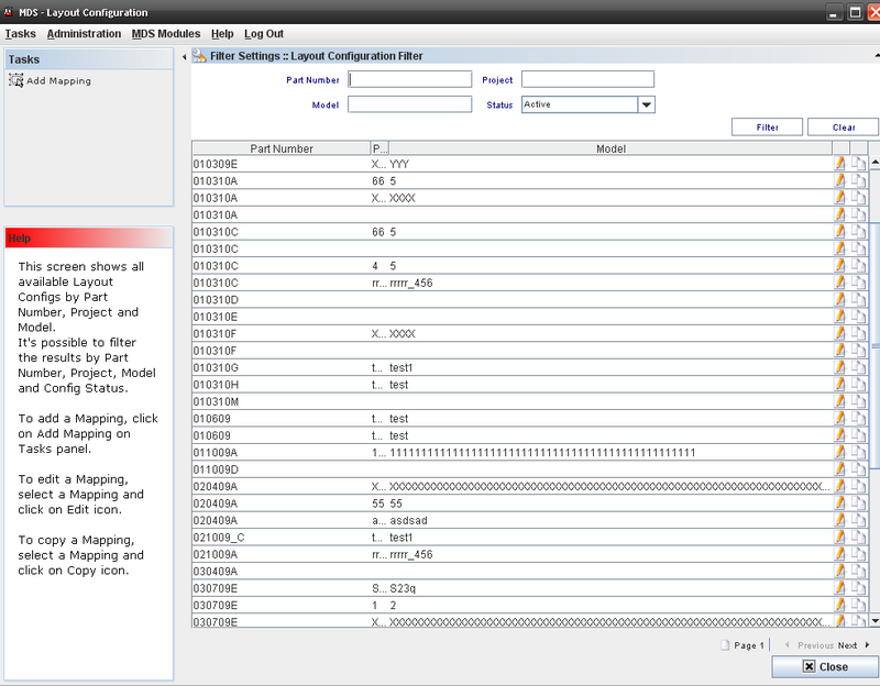
The Layout main window displays:
Figure 5: Layout Configuration Main Window
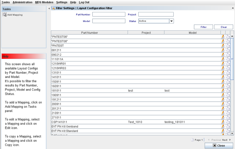
This screen will display all available Layout Configurations by Part Number, Project and Model.
Layout Configuration List
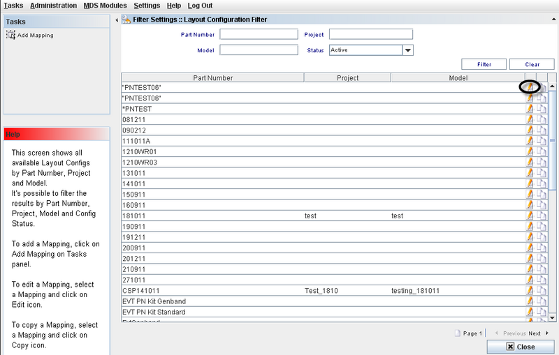
This screen displays all Layouts available and the user can edit or use the copy function.
Figure 6: Layout Configuration Filter
Adding a Mapping (Layout configuration)
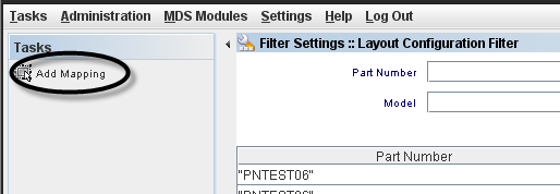
To create a Control Config, the user must to click onCreate Control Config on Tasks panel.
Figure 7: Add Mapping from Tasks panel
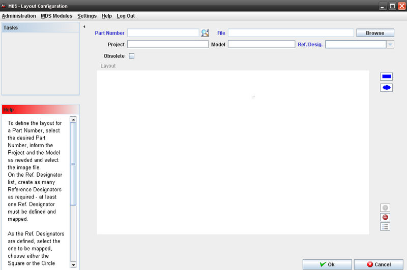
The Layout Configuration screen displays:
Figure 8: Layout Configuration screen
Note1: at least one Ref. Designator must be defined and mapped.
Fields that User can enter/select:
- Part Number;
- File
- Project;
- Model;
- Reference Designator;
- Browse to find the layout file;
Follow the steps below to define a layout for a part number:
- Select the desired Part Number; inform the Project and the Model as needed.
- Click on the “Browse” button to select the new assembly layout. The system will show the File Dialog window and the user can select the image. The system disables the button and the path text box and the image will appear in the layout box;
- On the Ref. Designator list, the user must to create as many Reference Designators as required which will then automatically appear as disabled;
- The user has to click in Square orCircle form Button and draw a Square or Rectangle in Layout;
- Click on the Add “+” button.
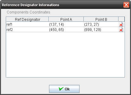
- At the same time a new row with the reference designator information will appear in the “UI control” box with the following variables:
Figure 9: Components Designator
To view the Reference Designator Information, click on the View button in the Layout Configuration window.
a.X coordinate;
b.Y coordinate;
c.Width;
d.Height;
- To delete the component, click on Delete icon.
- After adding all reference designators the user has to click on the “OK” button and the system will insert all these rows into the MDS Database;
Editing a Layout Configuration
Figure 10: Edit Layout configuration
To edit a Mapping, the user must to select a Mapping and click on Edit icon.
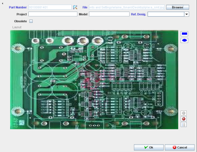
The Layout Configuration window displays with the existing layout information.
Figure 11: Layout Configuration
Note that the following fields can not be updated:
- Part Number
- Layout
- Project
- Model.
The Ref Designator can be removed from the list or included in the list.
To obsolete a configuration, check the Obsolete box.
Copying a Layout Configuration (mapping)
This option allows the user to create a new layout based on a pre existing layout (this module allows the user to copy and modify an existing assembly layout).
Follow the steps bellow to copy a layout:
- The user must create a new relation between the project and the model;
- Select the layout in the list and click the “Copy” button;
- The image will appear in the layout box, and all records will appear in the “UI control” grid;
- Select the part number that will have the layout chosen;
- In case the user wants to change any reference designator he/she has to select it on the assembly layout and the reference designator row that was selected will appear in the “UI control” grid.;
- Once the modification has been finished, the user has to click onOK button;
The system updates the information into the MDS database.
Test Configuration
Figure 25: Test Configuration window
This screen shows all Test Configurations.
Performing Searches
To perform searches, there are there are just one field available:
Filters Fields:
- Part Number;
- Test Configuration Name
- Top Level Assembly
- Location
Enter the information and click on Filter.
To clear the filter fields, click on Clear.
Adding/Editing Test Configuration;
See bellow the Add/Edit steps.
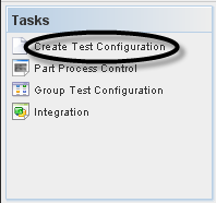
1. To add a Test Config, the user must to click on Add Test Config on Tasks panel.
Figure 26: Create Test Configuration
2. To edit or delete a Test Config, the user must to select the config in Test Config List and click on Edit or Delete icon.
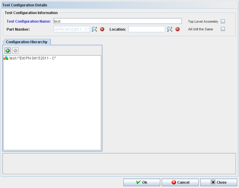
3. Click on Create Test Configuration in the Tasks Panel. The Create Test Configuration window displays.
Figure 27: Test Configuration Details
To add a test configuration, the user must to follow the following steps:
1. To create or edit a test configuration it's required to inform the top level Part Number.
2. To add a part number, a test configuration or a test configuration group to the test configuration, click on the "+" icon.
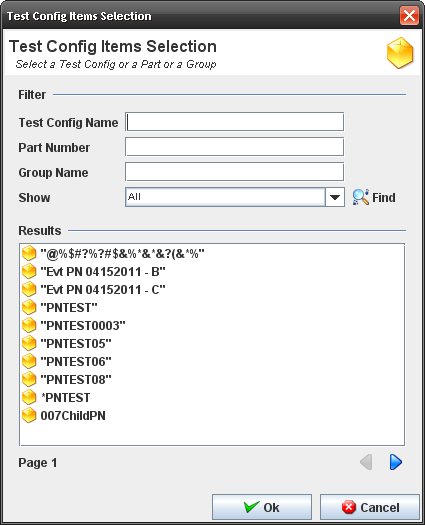
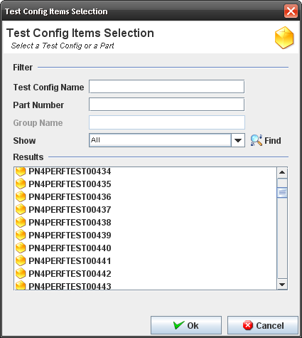
3. The Test Configuration Items Selection popup displays.
Figure 28: Test Config Items Selection
4. The user must enter a search item (your criteria: Part Number only, a Test Configuration Group or a Test Configuration only) and click on Find.
5. Double click on the result.
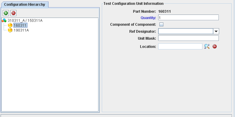
6. Fill mandatory fields (part number and quantity) in "Test Configuration Unit Information".
Figure 29: Test Configuration Details
7. Click on Ok button.
Note1: Obsolete Part Numbers do not display. The Part Number chosen will display in "Configuration Hierarchy".
The user can see the "Test Configuration Selection" window with "Test Configuration", "Part Number" and "Test Config Group"
Note2: It's possible to add more than one Test Configuration, Part Number or Test Config Group to create a Test Configuration.
8. The information is saved in the database.
9. The "Test Configuration" window closes and the Test Configuration created is displayed.
10. To delete a part number, a test configuration or a test configuration group from the control configuration, the user must select the item and click on the "-" icon.
Part Process Control;
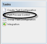
To manage Part Process Control, the user must to click on Part Process Control on Tasks panel.
Figure 30: Selecting Part Process Control
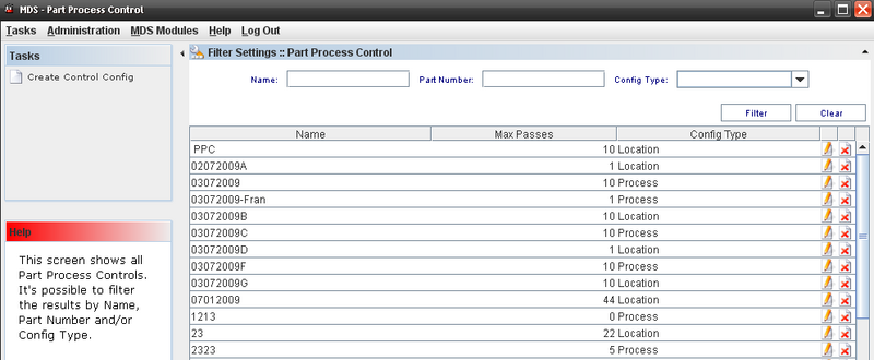
The Part Process control Window displays.
Figure 31: Part Process Control
This screen displays all Part Process Control available.
Editing or Deleting from Part Process Control List
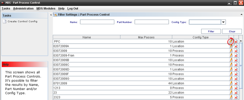
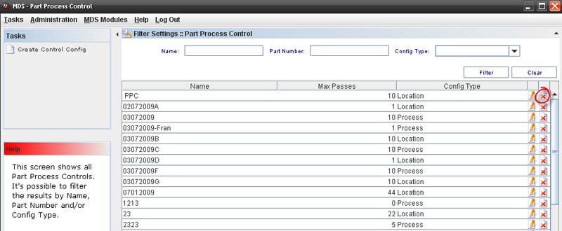
Figure 32: Editing a configuration from Part Process Control List
To Edit a Control Config, the user must to click on edit icon in the list.
The edit page displays:
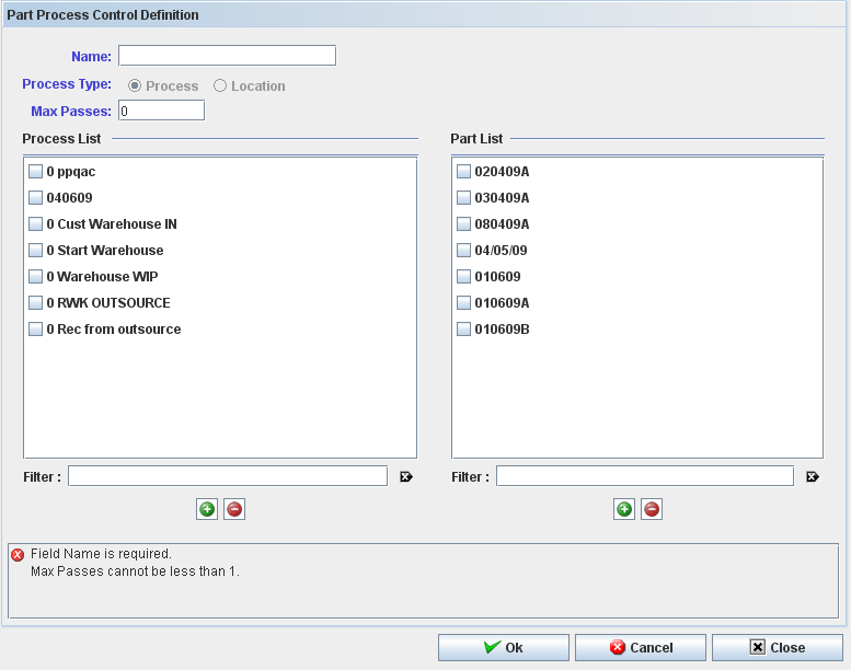
Figure 33: Part Process Control definition
Toupdate a part process control config it is required that the user type a unique name, the config type (process or location) and the max passes.
Note: All items of the control must be of the same type: process OR location.
At least one process or one location is required; the part number list is optional information.
To add a process or a location to the control config:
1. Click on the "+" icon below Process/Location list.
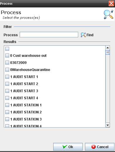
2. The Process popup displays:
Figure 34: Process Popup
3. Execute the filer to select an available process.
4. Click on OK button.
5. The selected process must display at the process list.
To delete a process or a location from the control config, select the process or location and click on the "-" icon below Process/Location list.
Click on Ok to confirm.
To add a part number to the control config, the steps are the same to add process:
1. Click on the "+" icon belowPart list.
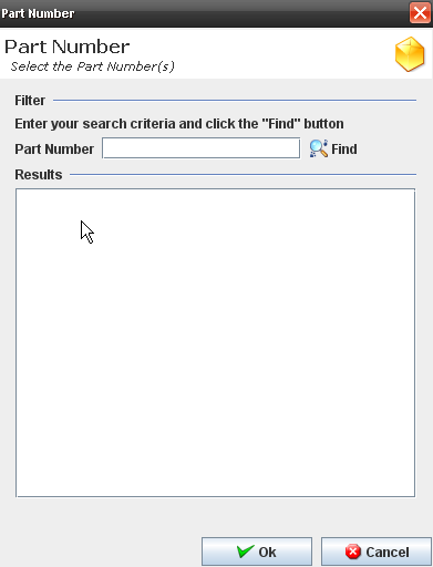
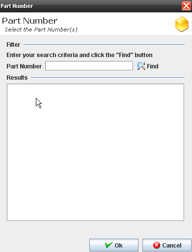
2. The part Popup displays:
Figure 35: Part Number dialog
3. Execute the filer to select an available part number.
4. Click on OK button.
The selected part must display at the process list.
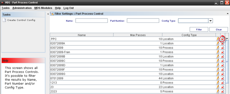
Figure 36: Deleting from Part Process Control List
To delete a Control Config, select the control and click on Delete icon in the main Part Process Control list window.
Click on Ok to confirm.
Creating a Control Configuration
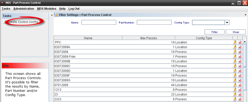
To create a Control Config, the user must to click onCreate Control Config on Tasks panel.
Figure 37: Create a Control Config
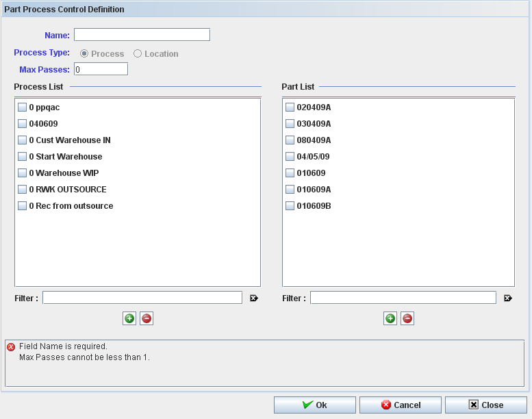
The Part Process Control Definition displays:
Figure 38: Part Process Control Definition
To create or edit a part process control config it is required to the user informs:
- Name;
- Config Type and
- Max Passes.
Note: All items of the control must be of the same type: process OR location.
At least one process or one location is required; the part number list is optional information.
To add a process or a location to the control config:
1. Click on the "+" icon below Process/Location list.
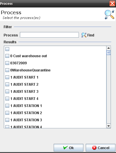
2. The process Popup displays:
Figure 39: Process Popup
3. Execute the filer to select an available process.
4. Click on OK button.
5. The selected process must display at the process list.
To delete a process or a location from the control config, select the process or location and click on the "-" icon below Process/Location list and click on Ok to confirm.
To add a part number to the control config, the steps are the same to add process:
1. Click on the "+" icon below Part list.
The part Popup displays:
Figure 40: Part Number
2. Execute the filer to select an available part number. 3. Click on OK button. 4. The selected part must display at the process list.
To delete a part number from the control config, select the part number and click on the "-" icon below Part list.
Figure 41: Deleting Control Config from Part Process Control List
To delete a Control Config, select the control and click on Delete icon in the main Part Process Control list window and click on Ok to confirm.
Group Test Configuration;
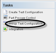
To manage Groups Test Config, the user must to click on Group Test Configuration on Tasks panel.
Figure 42: Test Configuration
To access the Group Test Config, click on Group Test Configuration in the Tasks panel.
Figure 43: Group Test Configuration List Filter
Sorting Colum
The application allows to sort all columns of the list (ascending or descending), including the multi-column sorting keeping the "control" key pressed.
Adding a Test Config Group
Figure 44: Adding Test Config Group
To add a Group, click on Add Test Config Group on Tasks panel.
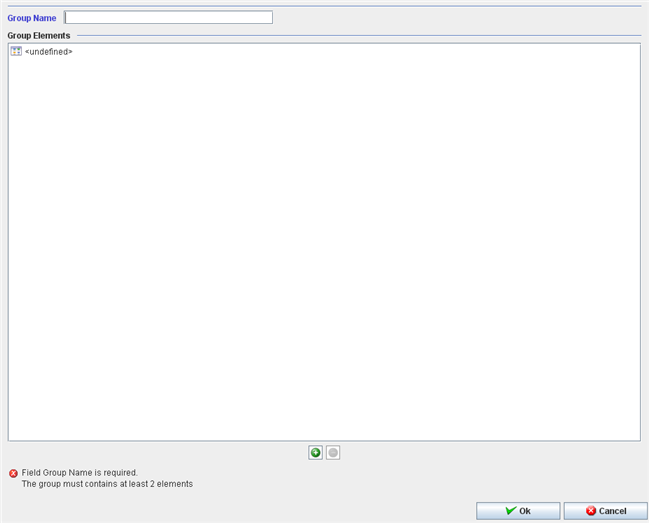
The Test Config Group window displays:
Figure 45: Adding Test Config Group
To create or edit a test config will be required to the user informs:
- Group Name;
To create or edit a test config group it will be required to the user to inform a unique group name.
All items of the group must be of the same type: test config OR part number.
To add a test config or a part number to the group:
1. Enter the new group name and click on the "+" icon.
2. The Test Config Items popup displays:
Figure 46: Config Items Popup
3. Execute the filter to select an available Test Config or part number.
4. Click on OK button.
5. The selected test config or part number must display at the group name element list.
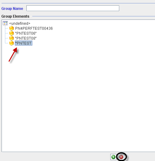
To delete a test config or a part number from the group, the user must to select the test config or the part number and click on the "-" icon.
Figure 47: Deleting Group Elements
Click on Ok to confirm.
Editing a group name.
Figure 48: Deleting Group Elements
To edit a group, select the group and click on Edit icon.
The same window to create a group displays. The user is able to change the group name or add/delete part numbers/test groups clicking on “+” icon to add or “-” icon to delete.
For more information, see the topic [#_Adding_a_Test 2.8.4.2 - Adding a Test Config Group].
Deleting a group name.
Figure 49: Deleting Group Names
To delete a Group, select the group and click on Delete icon.
Click on Ok to confirm.
Integration
To integrate a Top Assembly, scan or type the Component Serial Number according to the requested Ref. Designator.
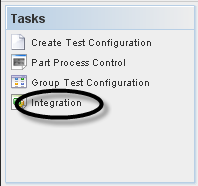
To integrate a Test Config, the user must to click on Integration on Tasks panel.
Figure 50: Test Configuration - Integration
Finding Top Assemblies to Integrate
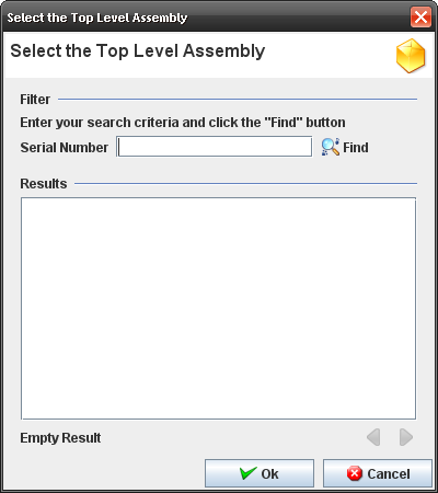
When the user clicks on "Integration" from Tasks panel, the screen to find and select the top assembly to integrate components is displayed.
Figure 51: Select the Top Assembly
Follow the steps below:
- Go to Kit Verify Test Configuration Integration, leave the Serial Number field empty or enter a S/N and click on Filter.
Note: Only top assembly serial numbers in status >=20 which have a test configuration created for the main part number must be displayed. The paginator buttons (previous and next) are displayed and 10 serial numbers are displayed per page.
Showing Integration Information
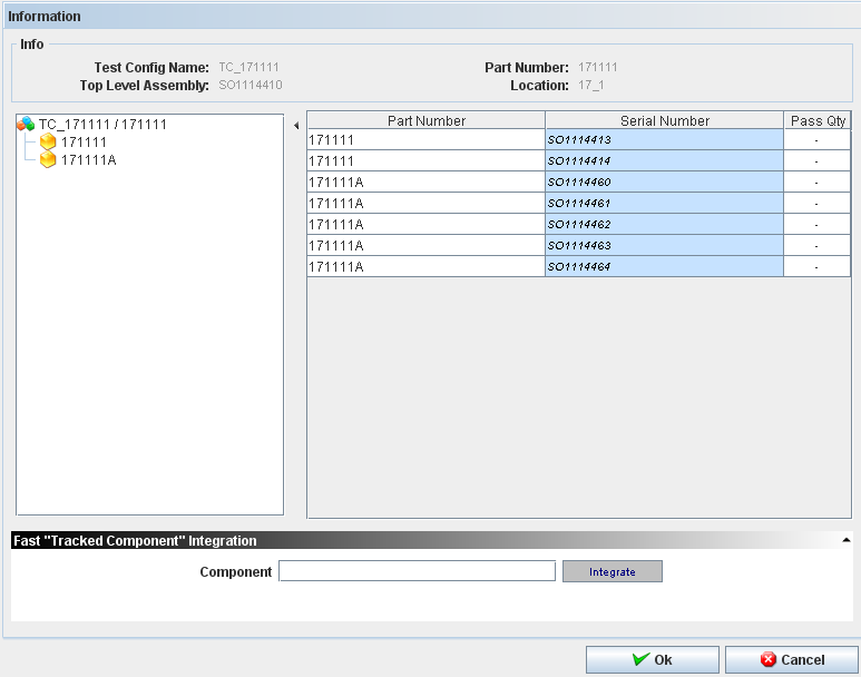
Figure 52: Integration Information
Follow the steps below:
- Go to Kit Verify Test Configuration Integration, fill the Serial Number field with the top assembly;
- Double click on top assembly;
- The test configuration tree view which was created for the main part number is displayed and beside that the components to integrate to the serial numbers are displayed;
- Click on Serial Number for the related part number, fill with one of the serial numbers created according to the pre condition 2 and press enter;
- The serial number is recorded to the part number and the application points to the next serial number to be filled;
- Repeat the step 3 for the remaining serial numbers and click OK;
- The message "Are you sure you want to create a new component integration?" is displayed.
Alert Distribution
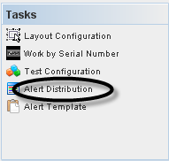
To access the Alert Distribution functionality, from Tasks panel, click on Alert Distribution.
Figure 53: Shop Order List
The alert distribution list should be like a profile. We can select the user for each program and these users will receive an email alert base on xml template.
The Alert Distribution list displays:
Figure 54: Alert Distribution
From this screen, the user is able to add, edit, copy or delete alerts distribution. See the next topics for more information.
Adding Alert Distribution
Figure 55: Adding Alert Distribution
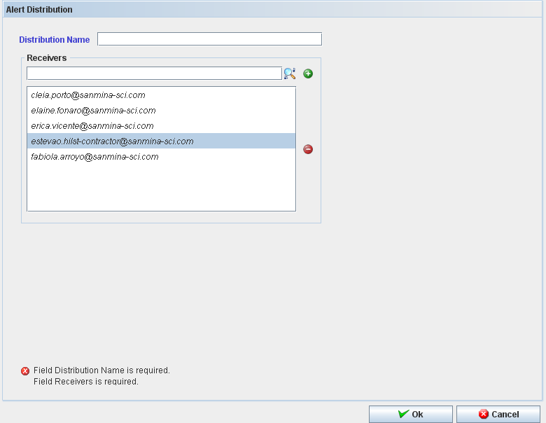
The Add Alert Distribution window displays:
Figure 56: Add Alert Distribution
To add an Alert Distribution, follow the steps bellow:
- In Task Panel click in "Add Alert Distribution" option;
- Fill the mandatory fields (Distribution Name and Receivers);
- Click in "Ok" button;
- Confirm the Alert Distribution creation.
The "Alert Distribution" window closes and the "Alert" is displayed with the recorded "Alert" in the table.
The user can search for receivers. Click on “+” to add or “-” to delete.
Editing Alert Distribution
Figure 57: Editing Alert Distribution.
Follow the steps bellow to edit an alert distribution:
- On the Alert Distribution list, select an existing Alert;
- Click the Edit icon; The Alert Distribution screen displays. It is the same for Add Distribution alert.
- Change the mandatory fields;
- Click "OK" button
- Confirm the Edit.
Copying Alert Distribution
Figure 58: Copying Alert Distribution
The copy feature allows the user to copy alert information. Follow the steps bellow:
- On the Alert Distribution List, select an existing Alert;
- Click the Copy Icon;
- Change the mandatory fields;
- Click "OK" button.
Deleting Alert Distribution
Figure 59: Deleting Alert Distribution
Follow the steps bellow to delete an Alert:
- On the Alert Distribution List, select an existing Alert;
- Click the Delete icon;
- Click "OK" button.
- A confirmation box displays.
- The Alert is deleted.
